Multinode High Availability in AWS Deployments
Read this topic to understand Multinode High Availability support for vSRX Virtual Firewall instances in Amazon Web Services (AWS) deployments.
Multinode High Availability in AWS
You can configure Multinode High Availability on the vSRX Virtual Firewall firewalls deployed on AWS. Participating nodes run both active control and data planes at the same time and the nodes backup each other to ensure a fast synchronized failover in case of system or hardware failure. The interchassis link (ICL) connection between the two devices synchronizes and maintains the state information and handles device failover scenarios.
Let's begin by getting familiar with the Multinode High Availability terms specific to the AWS deployment.
Terminology
| Term | Description |
|---|---|
|
Elastic IP address |
Public IPv4 address that is routable from a specified network or from the Internet. Elastic IP addresses are dynamically bound to an interface of any node in a Multinode High Availability setup. At any given time, these addresses are bound to only one interface and are also bound to the same node. The Multinode High Availability setup uses Elastic IP addresses to control the traffic in AWS deployments. Elastic IP address acts similar to floating IP address in the Layer 3 deployment or a virtual IP address as in the default gateway deployment. The node with an active SRG1 owns the Elastic IP address and draws the traffic toward it. |
|
Interchassis link (ICL) |
IP-based link (logical link) that connects nodes over a routed network in a Multinode High Availability system. The security device uses the ICL to synchronize and maintain the state information and to handle device failover scenarios. You can use only the ge-0/0/0 interface to configure an ICL. The ICL uses the MAC address assigned by AWS (not the virtual MAC created by vSRX Virtual Firewall). When you configure the ICL, ensure that the IP address is a subnet of of the virtual private cloud (VPC). Note that Multibode High Availability does not support cross-VPC deployment |
| Juniper Services Redundancy Protocol (jsrpd) process |
Process that manages activeness determination and enforcement, and provide split-brain protection. |
IPsec VPN Support
Starting in Junos OS Release 24.4R1, we support IPsec VPN for active/backup Multinode High Availability in AWS deployments.
Limitation
Multinode High Availability doesn’t support multiple SRG configurations (active/active) in public cloud deployments. Active/backup mode supports SRG0 and SRG1. IPsec VPN tunnel anchors at the SRG1, which works in a stateful active/backup mode. All VPN tunnels terminate on the device where the SRG1 is active.
Architecture
Figure 1 shows two vSRX Virtual Firewall instances form an HA pair in the Multinode High Availability deployment in AWS. One vSRX Virtual Firewall instance acts as the active node and the other as the backup node.
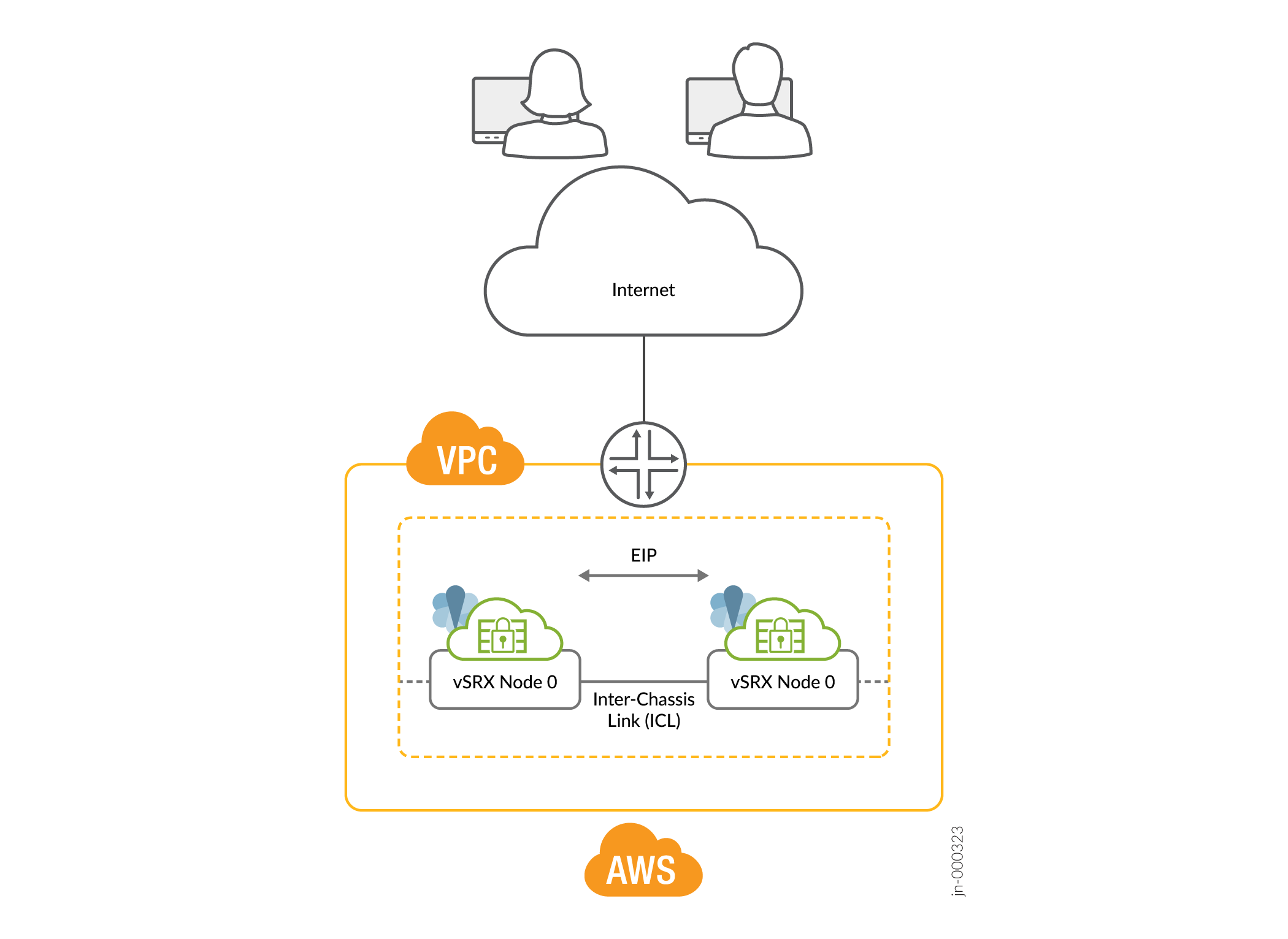
In a Multinode High Availability setup, an ICL connects the two nodes (vSRX Virtual Firewall instances) and helps synchronize the control-plane and data-plane states.
In Multinode High Availability setup, two vSRX Virtual Firewall instances are operating in active/backup mode. Both nodes connect to each other using an ICL for synchronizing control and data plane states. The vSRX Virtual Firewall instance on which the SRG1 is active hosts the Elastic IP address. The active node steers traffic toward it using the Elastic IP address. The backup node remains in standby mode and takes over on failover.
The Juniper Services Redundancy Protocol (jsrpd) process communicates with the AWS infrastructure to perform activeness determination and enforcement and provides split-brain protection.
During a failover, the Elastic IP address moves from the old active node to the new active node by triggering the AWS SDK API and draws traffic toward the new active node. AWS updates the route tables to divert the traffic to the new active node. This mechanism enables clients to communicate with the nodes using a single IP address. You configure the Elastic IP address on the interface that connects to participating networks/segments.
Split-Brain Protection
When the ICL between two nodes goes down, each node starts pinging to the peer node’s interface IP address using the probes. If the peer node is healthy, it responds to the probes. Otherwise, the jsrpd process communicates with the AWS infrastructure to enforce the active role for the healthy node.
Flexible ICL Interface on AWS
You can configure any ge-0/0/x interface for ICL on AWS. This is similar to ICL interface on Azure and GCP, where you can use ge-0/0/x for ICL. Previously, ICL interface on AWS was fixed and you could only use ge-0/0/0 for ICL.
For vSRX instances operating in an MNHA setup, AWS uses specific tags to ensure proper identification and management of HA pairs. Initially, two tags are used:
- LocalNodeID: This tag identifies the instance as the local node within the HA pair.
- PeerNodeID: This tag identifies the instance as peer node.
In addition to these two tags, we introduce four additional tags to enhance the configuration and management of MNHA setups by specifying interface details for both local and peer nodes:
- LocalTrustInterface: Interface on the local vSRX instance that connects to the private subnet (often used for trusted internal communication).
- LocalUntrustInterface: Interface on the local vSRX instance that connects to the public subnet (typically used for untrusted external communication).
- PeerTrustInterface: Interface on the peer vSRX instance that connects to the private subnet.
- PeerUntrustInterface: Interface on the peer vSRX instance that connects to the public subnet,
Support for Loopback Interface on AWS
As the AE interface is incompatible with public cloud platforms such as AWS, GCP, and Azure, the loopback interface is used as part of the dual path ICL solution. Azure and GCP support loopback interfaces. Now, you can use loopback interface to configure dual path ICL on AWS as well. AWS requires loopback communication must be established over two or more physical interfaces (example: ge-0/0/x).
The following illustration provides the topology of vSRX firewalls in MNHA setup deployed in AWS.
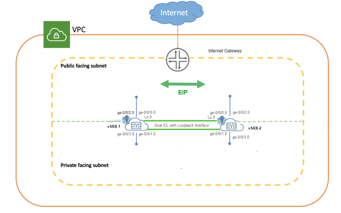
As shown in the topology, two vSRX Virtual Firewall instances (vSRX Virtual Firewall-1 and vSRX Virtual Firewall-2) are deployed in the Amazon VPC. The nodes communicate with each other using a routable IP address (Elastic IP address). The untrust side connects to a public network while the trust side connects to the protected resources
The topology uses loopback interfaces to implement dual path Inter-Chassis Link
(ICL) between two vSRX firewalls within a VPC. vSRX devices use two interfaces
(ge-0/0/0 and ge-0/0/1) each for dual ICL
connectivity. Here, loopback interface is used as the logical endpoint for ICL
communication. Physical Interfaces (ge-0/0/0 and
ge-0/0/1) serve as the underlying transport paths for
loopback communication.
Example: Configure Multinode High Availability in AWS Deployment
In this example, we'll show you how to configure Multinode High Availability on two vSRX Virtual Firewall instances in the Amazon Virtual Private Cloud (Amazon VPC).
Requirements
This example uses the following components:
-
Two vSRX Virtual Firewall instances
-
Junos OS Release 22.3R1
-
An Amazon Web Services (AWS) account and an identity and access management (IAM) role, with all required permissions to access, create, modify, and delete Amazon Elastic Compute Cloud (Amazon EC2), Amazon Simple Storage Service (S3), and Amazon Virtual Private Cloud (Amazon VPC) objects. See Configure an Amazon Virtual Private Cloud for vSRX for details.
-
An Amazon VPC configured with its associated Internet gateway, subnets, route table, and security groups. See Configure an Amazon Virtual Private Cloud for vSRX.
-
A vSRX Virtual Firewall instance launched and configured in Amazon VPC. See Launch a vSRX Instance on an Amazon Virtual Private Cloud.
Topology
Figure 3 shows the topology used in this example.
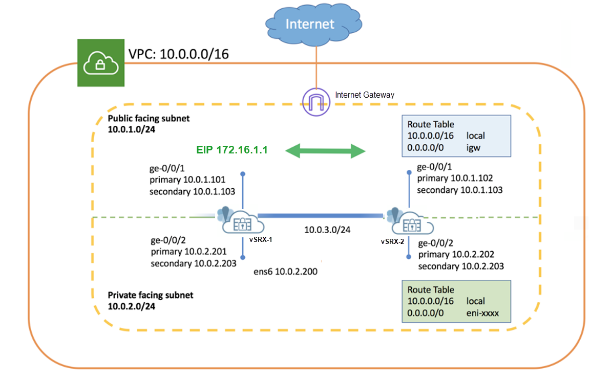
As shown in the topology, two vSRX Virtual Firewall instances (vSRX Virtual Firewall-1 and vSRX Virtual Firewall-2) are deployed in the Amazon VPC. The nodes communicate with each other using a routable IP address (Elastic IP address). The untrust side connects to a public network while the trust side connects to the protected resources.
Complete the following configurations before configuring Multinode High Availability on the vSRX Virtual Firewall instances:
-
Use instance tag in AWS to identify the two vSRX Virtual Firewall instances as Multinode High Availability peers. For example, you can use vsrx-node-1 as the name of one peer (Name option) and vsrx-node-2 as the HA peer (ha-peer option).
- Deploy both vSRX Virtual Firewall instances in the same Amazon VPC and availability zone.
- Assign IAM role for both the vSRX Virtual Firewall instances and launch vSRX Virtual Firewall instances as a Amazon Elastic Compute Cloud (EC2) instance with full permissions.
- Enable communication to the Internet by placing vSRX Virtual Firewall instances in the public subnet. In the Amazon VPC, public subnets have access to the Internet gateway.
- Configure a VPC with multiple subnets to host the high availability pair.
The subnets are used to connect the two vSRX Virtual Firewall nodes using a
logical connection (similar to the physical cable connecting ports). In this
example, we have defined CIDR for VPC as 10.0.0.0/16, and created a total of
four subnets to host the vSRX Virtual Firewall traffic. You need a minimum
of four interfaces for both vSRX Virtual Firewall instances. Table 1 provides
the subnet and interface details.
Table 1: Subnets Configurations Function Port Number Interface Connection Traffic Type Subnet Management 0 fxp0 Management interface Management traffic 10.0.254.0/24 ICL 1 ge-0/0/0 ICL to peer node RTO, sync, and probes-related traffic 10.0.253.0/24 Public 2 ge-0/0/1 Connect to public network. (Revenue interface) External traffic 10.0.1.0/24 Private 3 ge-0/0/2 Connect to private network. (Revenue interface) Internal traffic 10.0.2.0/24 Note that the interface mapping with functionality mentioned in the table is for default configuration. We recommend to use the same mapping in the configuration.
- Configure interfaces with primary and secondary IP addresses. You can assign
Elastic IP address as secondary IP addresses for an interface. You need the
primary IP address while launching the instance. The secondary IP address is
transferable from one vSRX Virtual Firewall node to another during a
failover. Table 2 shows interface and IP address mappings used in this example.
Table 2: Interface and IP Address Mappings Instance Interface Primary IP Address Secondary IP Address (Elastic IP Address) vSRX Virtual Firewall-1 ge-0/0/1 10.0.1.101 10.0.1.103 ge-0/0/2 10.0.2.201 10.0.2.203 vSRX Virtual Firewall-2 ge-0/0/1 10.0.1.102 10.0.1.103 ge-0/0/2 10.0.2.202 10.0.2.203 -
Configure neighboring routers to include vSRX Virtual Firewall in the data path and mark vSRX Virtual Firewall as the next hop for the traffic. You can use an Elastic IP address to configure the route. For example, use the command
sudo ip route x.x.x.x/x dev ens6 via
                                10.0.2.203
, where the 10.0.2.203 address is an Elastic IP address.
Configuration
CLI Quick Configuration
To quickly configure this example, copy the following commands, paste them
into a text file, remove any line breaks, change any details necessary to
match your network configuration, copy and paste the commands into the CLI
at the [edit] hierarchy level, and then enter
commit from configuration mode.
These configurations are captured from a lab environment, and are provided for reference only. Actual configurations may vary based on the specific requirements of your environment.
On vSRX Virtual Firewall-1
set chassis high-availability local-id 1
set chassis high-availability local-id local-ip 10.0.3.10
set chassis high-availability peer-id 2 peer-ip 10.0.3.11
set chassis high-availability peer-id 2 interface ge-0/0/0.0
set chassis high-availability peer-id 2 liveness-detection minimum-interval 400
set chassis high-availability peer-id 2 liveness-detection multiplier 5
set chassis high-availability services-redundancy-group 1 deployment-type cloud
set chassis high-availability services-redundancy-group 1 peer-id 2
set chassis high-availability services-redundancy-group 1 preemption
set chassis high-availability services-redundancy-group 1 activeness-priority 200
set security policies default-policy permit-all
set security zones security-zone fab host-inbound-traffic system-services all
set security zones security-zone fab host-inbound-traffic protocols all
set security zones security-zone fab interfaces ge-0/0/0.0
set security zones security-zone untrust host-inbound-traffic system-services all
set security zones security-zone untrust host-inbound-traffic protocols all
set security zones security-zone untrust interfaces ge-0/0/1.0
set security zones security-zone trust host-inbound-traffic system-services all
set security zones security-zone trust host-inbound-traffic protocols all
set security zones security-zone trust interfaces ge-0/0/2.0
set security cloud high-availability aws eip-based
set security cloud high-availability aws peer-liveliness probe-ip 10.0.1.102
set security cloud high-availability aws peer-liveliness probe-ip routing-instance s1-router
set interfaces ge-0/0/0 mtu 9192
set interfaces ge-0/0/0 unit 0 family inet address 10.0.3.10/24
set interfaces ge-0/0/1 mtu 9192
set interfaces ge-0/0/1 unit 0 family inet address 10.0.1.101/24 primary
set interfaces ge-0/0/1 unit 0 family inet address 10.0.1.103/24
set interfaces ge-0/0/2 mtu 9192
set interfaces ge-0/0/2 unit 0 family inet address 10.0.2.201/24 primary
set interfaces ge-0/0/2 unit 0 family inet address 10.0.2.203/24
set routing-instances s1-router instance-type virtual-router
set routing-instances s1-router routing-options static route 0.0.0.0/0 next-hop 10.0.1.1
set routing-instances s1-router interface ge-0/0/1.0
set routing-instances s1-router interface ge-0/0/2.0
On vSRX Virtual Firewall-2
set chassis high-availability local-id 2
set chassis high-availability local-id local-ip 10.0.3.11
set chassis high-availability peer-id 1 peer-ip 10.0.3.10
set chassis high-availability peer-id 1 interface ge-0/0/0.0
set chassis high-availability peer-id 1 liveness-detection minimum-interval 400
set chassis high-availability peer-id 1 liveness-detection multiplier 5
set chassis high-availability services-redundancy-group 1 deployment-type cloud
set chassis high-availability services-redundancy-group 1 peer-id 1
set chassis high-availability services-redundancy-group 1 preemption
set chassis high-availability services-redundancy-group 1 activeness-priority 100
set security policies default-policy permit-all
set security zones security-zone fab host-inbound-traffic system-services all
set security zones security-zone fab host-inbound-traffic protocols all
set security zones security-zone fab interfaces ge-0/0/0.0
set security zones security-zone untrust host-inbound-traffic system-services all
set security zones security-zone untrust host-inbound-traffic protocols all
set security zones security-zone untrust interfaces ge-0/0/1.0
set security zones security-zone trust host-inbound-traffic system-services all
set security zones security-zone trust host-inbound-traffic protocols all
set security zones security-zone trust interfaces ge-0/0/2.0
set security cloud high-availability aws eip-based
set security cloud high-availability aws peer-liveliness probe-ip 10.0.1.101
set security cloud high-availability aws peer-liveliness probe-ip routing-instance s1-router
set interfaces ge-0/0/0 mtu 9192
set interfaces ge-0/0/0 unit 0 family inet address 10.0.3.11/24
set interfaces ge-0/0/1 mtu 9192
set interfaces ge-0/0/1 unit 0 family inet address 10.0.1.102/24 primary
set interfaces ge-0/0/1 unit 0 family inet address 10.0.1.103/24
set interfaces ge-0/0/2 mtu 9192
set interfaces ge-0/0/2 unit 0 family inet address 10.0.2.202/24 primary
set interfaces ge-0/0/2 unit 0 family inet address 10.0.2.203/24
set routing-instances s1-router instance-type virtual-router
set routing-instances s1-router routing-options static route 0.0.0.0/0 next-hop 10.0.1.1
set routing-instances s1-router interface ge-0/0/1.0
set routing-instances s1-router interface ge-0/0/2.0
Step-by-Step Procedure
The following example requires you to navigate various levels in the configuration hierarchy. For instructions on how to do that, see Using the CLI Editor in Configuration Mode in the CLI User Guide.
-
Configure ge-0/0/0 as the interface for the ICL
[edit]
user@host# set interfaces ge-0/0/0 mtu 9192
user@host# set interfaces ge-0/0/0 unit 0 family inet address 10.0.3.11/24
- Configure interfaces for internal and external traffic.
[edit]
user@host# set interfaces ge-0/0/1 mtu 9192
user@host# set interfaces ge-0/0/1 unit 0 family inet address 10.0.1.102/24 primary
user@host# set interfaces ge-0/0/1 unit 0 family inet address 10.0.1.103/24
user@host# set interfaces ge-0/0/2 mtu 9192
user@host# set interfaces ge-0/0/2 unit 0 family inet address 10.0.2.202/24 primary
user@host# set interfaces ge-0/0/2 unit 0 family inet address 10.0.2.203/24
We'll use the secondary IP address assigned to ge-0/0/1 and ge-0/0/2 as Elastic IP address.
-
Configure security zones, assign interfaces to the zones, and specify allowed system services for the security zones .
[edit]
user@host# set security zones security-zone fab host-inbound-traffic system-services all
user@host# set security zones security-zone fab host-inbound-traffic protocols all
user@host# set security zones security-zone fab interfaces ge-0/0/0.0
user@host# set security zones security-zone untrust host-inbound-traffic system-services all
user@host# set security zones security-zone untrust host-inbound-traffic protocols all
user@host# set security zones security-zone untrust interfaces ge-0/0/1.0
user@host# set security zones security-zone trust host-inbound-traffic system-services all
user@host# set security zones security-zone trust host-inbound-traffic protocols all
user@host# set security zones security-zone trust interfaces ge-0/0/2.0
-
Configure routing options.
[edit]
user@host# set routing-instances s1-router instance-type virtual-router
user@host# set routing-instances s1-router routing-options static route 0.0.0.0/0 next-hop 10.0.1.1
user@host# set routing-instances s1-router interface ge-0/0/1.0
user@host# set routing-instances s1-router interface ge-0/0/2.0
Here, you'll require a separate routing instance type
virtual
                                    router
to separate management traffic and revenue traffic. -
Configure local node and peer node details.
[edit]
user@host# set chassis high-availability local-id 1
user@host# set chassis high-availability local-id local-ip 10.0.3.10
user@host# set chassis high-availability peer-id 2 peer-ip 10.0.3.11
-
Associate the interface to the peer node for interface monitoring, and configure the liveness detection details.
[edit]
user@host# set chassis high-availability peer-id 2 interface ge-0/0/0.0
user@host# set chassis high-availability peer-id 2 liveness-detection minimum-interval 400
user@host# set chassis high-availability peer-id 2 liveness-detection multiplier 5
-
Configure SRG1 with deployment type as cloud, assign an ID, and set preemption and activeness priority.
[edit]
user@host# set chassis high-availability services-redundancy-group 1 deployment-type cloud
user@host# set chassis high-availability services-redundancy-group 1 peer-id 2
user@host# set chassis high-availability services-redundancy-group 1 preemption
user@host# set chassis high-availability services-redundancy-group 1 activeness-priority 200
-
Configure AWS deployment-related options. For example, specify eip-based as the service type and also, configure monitoring options such as AWS peer liveness.
[edit]
user@host# set security cloud high-availability aws eip-based
user@host# set security cloud high-availability aws peer-liveliness probe-ip 10.0.1.101
user@host# set security cloud high-availability aws peer-liveliness probe-ip routing-instance s1-router
In Multinode High Availability for vSRX Virtual Firewall instances in VMWare ESXi environment with VMXNET3 vNIC, configuration of virtual MAC address is not supported in the following statement:
[set chassis high-availability services-redundancy-group <number> virtual-ip <id> use-virtual-mac
Results
vSRX Virtual Firewall-1
From configuration mode, confirm your configuration by entering the following commands.
If the output does not display the intended configuration, repeat the configuration instructions in this example to correct it.
[edit]
user@host# show chassis high-availability
local-id 1 local-ip 10.0.3.10;
peer-id 2 {
    peer-ip 10.0.3.11;
    interface ge-0/0/0.0;
    liveness-detection {
        minimum-interval 400;
        multiplier 5;
    }
}
services-redundancy-group 1 {
    deployment-type cloud;
    peer-id {
        2;
    }
    preemption;
    activeness-priority 200;
}
[edit]
user@host# show routing-instances
s1-router {
    instance-type virtual-router;
    routing-options {
        static {
            route 0.0.0.0/0 next-hop 10.0.1.1;
        }
    }
    interface ge-0/0/1.0;
    interface ge-0/0/2.0;
}
[edit]
user@host# show security zones security-zone
   security-zone fab {
    host-inbound-traffic {
        system-services {
            all;
        }
        protocols {
            all;
        }
    }
    interfaces {
        ge-0/0/0.0;
    }
}
security-zone untrust {
    host-inbound-traffic {
        system-services {
            all;
        }
        protocols {
            all;
        }
    }
    interfaces {
        ge-0/0/1.0;
    }
}
security-zone trust {
    host-inbound-traffic {
        system-services {
            all;
        }
        protocols {
            all;
        }
    }
    interfaces {
        ge-0/0/2.0;
    }
}
[edit]
user@host# show interfaces
ge-0/0/0 {
    mtu 9192;
    unit 0 {
        family inet {
            address 10.0.3.10/24;
        }
    }
}
ge-0/0/1 {
    mtu 9192;
    unit 0 {
        family inet {
            address 10.0.1.101/24 {
                primary;
            }
            address 10.0.1.103/24;
        }
    }
}
ge-0/0/2 {
    mtu 9192;
    unit 0 {
        family inet {
            address 10.0.2.201/24 {
                primary;
            }
            address 10.0.2.203/24;
        }
    }
}
If you are done configuring the device, enter commit from
configuration mode.
vSRX Virtual Firewall-2
From configuration mode, confirm your configuration by entering the following commands.
If the output does not display the intended configuration, repeat the configuration instructions in this example to correct it.
[edit]
user@host# show chassis high-availability
local-id 2 local-ip 10.0.3.11;
peer-id 1 {
    peer-ip 10.0.3.10;
    interface ge-0/0/0.0;
    liveness-detection {
        minimum-interval 400;
        multiplier 5;
    }
}
services-redundancy-group 1 {
    deployment-type cloud;
    peer-id {
        1;
    }
    preemption;
    activeness-priority 100;
}
[edit]
user@host# show routing-instances
s1-router {
    instance-type virtual-router;
    routing-options {
        static {
            route 0.0.0.0/0 next-hop 10.0.1.1;
        }
    }
    interface ge-0/0/1.0;
    interface ge-0/0/2.0;
}
[edit]
user@host# show security zones
  security-zone fab {
    host-inbound-traffic {
        system-services {
            all;
        }
        protocols {
            all;
        }
    }
    interfaces {
        ge-0/0/0.0;
    }
}
security-zone untrust {
    host-inbound-traffic {
        system-services {
            all;
        }
        protocols {
            all;
        }
    }
    interfaces {
        ge-0/0/1.0;
    }
}
security-zone trust {
    host-inbound-traffic {
        system-services {
            all;
        }
        protocols {
            all;
        }
    }
    interfaces {
        ge-0/0/2.0;
    }
}
[edit]
user@host# show interfaces
ge-0/0/0 {
    mtu 9192;
    unit 0 {
        family inet {
            address 10.0.3.11/24;
        }
    }
}
ge-0/0/1 {
    mtu 9192;
    unit 0 {
        family inet {
            address 10.0.1.102/24 {
                primary;
            }
            address 10.0.1.103/24;
        }
    }
}
ge-0/0/2 {
    mtu 9192;
    unit 0 {
        family inet {
            address 10.0.2.202/24 {
                primary;
            }
            address 10.0.2.203/24;
        }
    }
}
If you are done configuring the device, enter commit from
configuration mode.
Verification
- Check Multinode High Availability Details
- Check Multinode High Availability Information on AWS
- Check Multinode High Availability Peer Node Status
- Check Multinode High Availability SRG
- Verify the Multinode High Availability Status Before and After Failover
Check Multinode High Availability Details
Purpose
View and verify the details of the Multinode High Availability setup configured on your vSRX Virtual Firewall instance.
Action
From operational mode, run the following command:
vSRX Virtual Firewall-1
user@host> show chassis high-availability information
            Node failure codes:
    HW  Hardware monitoring    LB  Loopback monitoring
    MB  Mbuf monitoring        SP  SPU monitoring
    CS  Cold Sync monitoring   SU  Software Upgrade

Node Status: ONLINE
Local-id: 1
Local-IP: 10.0.3.10
HA Peer Information:

    Peer Id: 2        IP address: 10.0.3.11     Interface: ge-0/0/0.0
    Routing Instance: default
    Encrypted: NO     Conn State: UP
    Cold Sync Status: COMPLETE

SRG failure event codes:
    BF  BFD monitoring
    IP  IP monitoring
    IF  Interface monitoring
    CP  Control Plane monitoring

Services Redundancy Group: 1
        Deployment Type: CLOUD
        Status: ACTIVE
        Activeness Priority: 200
        Preemption: ENABLED
        Process Packet In Backup State: NO
        Control Plane State: READY
        System Integrity Check: N/A
        Failure Events: NONE
        Peer Information:
          Peer Id: 2
          Status : BACKUP
          Health Status: HEALTHY
          Failover Readiness: NOT READY
vSRX Virtual Firewall-2
user@host> show chassis high-availability information
Node failure codes:
    HW  Hardware monitoring    LB  Loopback monitoring
    MB  Mbuf monitoring        SP  SPU monitoring
    CS  Cold Sync monitoring   SU  Software Upgrade

Node Status: ONLINE
Local-id: 2
Local-IP: 10.0.3.11
HA Peer Information:

    Peer Id: 1        IP address: 10.0.3.10     Interface: ge-0/0/0.0
    Routing Instance: default
    Encrypted: NO     Conn State: UP
    Cold Sync Status: COMPLETE

SRG failure event codes:
    BF  BFD monitoring
    IP  IP monitoring
    IF  Interface monitoring
    CP  Control Plane monitoring

Services Redundancy Group: 1
        Deployment Type: CLOUD
        Status: BACKUP
        Activeness Priority: 100
        Preemption: ENABLED
        Process Packet In Backup State: NO
        Control Plane State: NOT READY
        System Integrity Check: COMPLETE
        Failure Events: NONE
        Peer Information:
          Peer Id: 1
          Status : ACTIVE
          Health Status: HEALTHY
          Failover Readiness: N/A
Meaning
Verify these details from the command output:
-
Local node and peer node details such as IP address and ID.
-
The field
Deployment Type: CLOUDindicates that configuration is for the cloud deployment. -
The field
Services Redundancy Group: 1indicates the status of the SRG1 (ACTIVE or BACKUP) on that node.
Check Multinode High Availability Information on AWS
Purpose
Check whether Multinode High Availability is deployed in AWS cloud.
Action
From operational mode, run the following command:
user@host> show security cloud high-availability information
   Cloud HA Information:

    Cloud Type      Cloud Service Type   Cloud Service Status
    AWS             EIP                  Bind to Local Node
Meaning
Verify these details from the command output:
-
The field
Cloud Type: AWSindicates the deployment is for AWS. -
The field
Cloud Service Type: EIPindicates that the the AWS deployment uses the EIP service type (for Elastic IP address) to control traffic. -
The field
.Cloud Service Status: Bind to Local Nodeindicates the binding of the Elastic IP address to the local node. For the backup node, this field displaysBind to Peer Node.
Check Multinode High Availability Peer Node Status
Purpose
Check the Multinode High Availability peer node status.
Action
From operational mode, run the following command:
vSRX Virtual Firewall-1
user@host> show chassis high-availability peer-info
     HA Peer Information:

   Peer-ID: 2        IP address: 10.0.3.11     Interface: ge-0/0/0.0
   Routing Instance: default
   Encrypted: NO     Conn State: UP
   Cold Sync Status: COMPLETE
   Internal Interface: N/A
   Internal Local-IP: N/A
   Internal Peer-IP: N/A
   Internal Routing-instance: N/A
Packet Statistics:
        Receive Error : 0        Send Error : 0

        Packet-type            Sent       Received

        SRG Status Msg           7           6

        SRG Status Ack            6           7

        Attribute Msg             2           1

        Attribute Ack             1           1
vSRX Virtual Firewall-2
user@host> show chassis high-availability peer-info
HA Peer Information:

   Peer-ID: 1        IP address: 10.0.3.10     Interface: ge-0/0/0.0
   Routing Instance: default
   Encrypted: NO     Conn State: UP
   Cold Sync Status: COMPLETE
   Internal Interface: N/A
   Internal Local-IP: N/A
   Internal Peer-IP: N/A
   Internal Routing-instance: N/A
Packet Statistics:
        Receive Error : 0        Send Error : 0

        Packet-type            Sent       Received

        SRG Status Msg           9           9

        SRG Status Ack            9           9

        Attribute Msg             3           2

        Attribute Ack             2           2
Meaning
Verify these details from the command output:
-
Peer node details including ID, IP address, interface.
-
Packet statistics across the node.
Check Multinode High Availability SRG
Purpose
View and verify SRG details in Multinode High Availability.
Action
From operational mode, run the following command:
user@host> show chassis high-availability services-redundancy-group 1
            SRG failure event codes:
    BF  BFD monitoring
    IP  IP monitoring
    IF  Interface monitoring
    CP  Control Plane monitoring

Services Redundancy Group: 1
        Deployment Type: CLOUD
        Status: ACTIVE
        Activeness Priority: 200
        Preemption: ENABLED
        Process Packet In Backup State: NO
        Control Plane State: READY
        System Integrity Check: N/A
        Failure Events: NONE
        Peer Information:
          Peer Id: 2
          Status : BACKUP
          Health Status: HEALTHY
          Failover Readiness: READY

        Split-brain Prevention Probe Info:
          DST-IP: 10.0.1.102
          SRC-IP: 0.0.0.0
          Routing Instance: s1-router
          Status: NOT RUNNING
          Result: N/A           Reason: N/A
Meaning
Verify these details from the command output:
-
SRG details such deployment type. The field
Status:
                                    ACTIVE
indicates that the particular SRG1 is in active role. You can also view activeness priority and preemption state in the output. -
Peer node details.
-
Split-brain prevention probe details.
Verify the Multinode High Availability Status Before and After Failover
Purpose
Check the change in node status before and after a failover in a Multinode High Availability setup.
Action
Check the Multinode High Availability status on the backup node (SRX-2).
From operational mode, run the following command:
user@host> show chassis high-availability information
            Node failure codes:
    HW  Hardware monitoring    LB  Loopback monitoring
    MB  Mbuf monitoring        SP  SPU monitoring
    CS  Cold Sync monitoring   SU  Software Upgrade

Node Status: ONLINE
Local-id: 2
Local-IP: 10.0.3.11
HA Peer Information:

    Peer Id: 1        IP address: 10.0.3.10     Interface: ge-0/0/0.0
    Routing Instance: default
    Encrypted: NO     Conn State: UP
    Cold Sync Status: COMPLETE

SRG failure event codes:
    BF  BFD monitoring
    IP  IP monitoring
    IF  Interface monitoring
    CP  Control Plane monitoring

Services Redundancy Group: 1
        Deployment Type: CLOUD
        Status: BACKUP
        Activeness Priority: 100
        Preemption: ENABLED
        Process Packet In Backup State: NO
        Control Plane State: NOT READY
        System Integrity Check: COMPLETE
        Failure Events: NONE
        Peer Information:
          Peer Id: 1
          Status : ACTIVE
          Health Status: HEALTHY
          Failover Readiness: N/A
Meaning
In Services Redundancy Group: 1 section, you can see the
Status: BACKUP. This field indicates that the SRG-1 is
in the backup mode.
Action
Initiate the failover on the active node (vSRX Virtual Firewall-1) and again run the command on the backup node (vSRX Virtual Firewall-2).
user@host> show chassis high-availability information
Node failure codes:
    HW  Hardware monitoring    LB  Loopback monitoring
    MB  Mbuf monitoring        SP  SPU monitoring
    CS  Cold Sync monitoring   SU  Software Upgrade

Node Status: ONLINE
Local-id: 2
Local-IP: 10.0.3.11
HA Peer Information:

    Peer Id: 1        IP address: 10.0.3.10     Interface: ge-0/0/0.0
    Routing Instance: default
    Encrypted: NO     Conn State: UP
    Cold Sync Status: COMPLETE

SRG failure event codes:
    BF  BFD monitoring
    IP  IP monitoring
    IF  Interface monitoring
    CP  Control Plane monitoring

Services Redundancy Group: 1
        Deployment Type: CLOUD
        Status: ACTIVE
        Activeness Priority: 100
        Preemption: ENABLED
        Process Packet In Backup State: NO
        Control Plane State: READY
        System Integrity Check: N/A
        Failure Events: NONE
        Peer Information:
          Peer Id: 1
          Status : BACKUP
          Health Status: HEALTHY
          Failover Readiness: NOT READY
Meaning
In the Services Redundancy Group: 1 section, the status of
SRG1 changes from BACKUP to ACTIVE. The
change in the field value indicates that the node has transitioned into the
active role and the other node (previously active) has transitioned to the
backup role. You can see the other node's status in the Peer
Information option, which shows BACKUP.
See Also
Change History Table
Feature support is determined by the platform and release you are using. Use Feature Explorer to determine if a feature is supported on your platform.