ON THIS PAGE
Example: Configuring an Active/Passive Chassis Cluster Pair (SRX1500 or SRX1600)
Example: Configuring an Active/Passive Chassis Cluster Pair (J-Web)
Understand Active/Passive Chassis Cluster Deployment with an IPsec Tunnel
Example: Configure an Active/Passive Chassis Cluster Pair with an IPsec Tunnel
Example: Configure an Active/Passive Chassis Cluster Pair with an IPsec Tunnel (J-Web)
Active/Passive Chassis Cluster Deployments
Learn how to configure basic active/passive chassis clustering on a Firewalls.
Understand Active/Passive Chassis Cluster Deployment
In this configuration, one device in the cluster handles all traffic under normal operation, while the other device remains on standby and is used only if a failure occurs. See Figure 1. When a failure is detected, the standby device assumes the primary role and takes over all traffic forwarding.
An active/passive chassis cluster can be implemented by assigning all redundant Ethernet (reth) interfaces to the same redundancy group. If any interface in the active group on a node fails, the redundancy group becomes inactive and all interfaces in the group fail over to the peer node.
This configuration minimizes traffic over the fabric link because only one node forwards traffic at any given time.
See Also
Example: Configure an Active/Passive Chassis Cluster
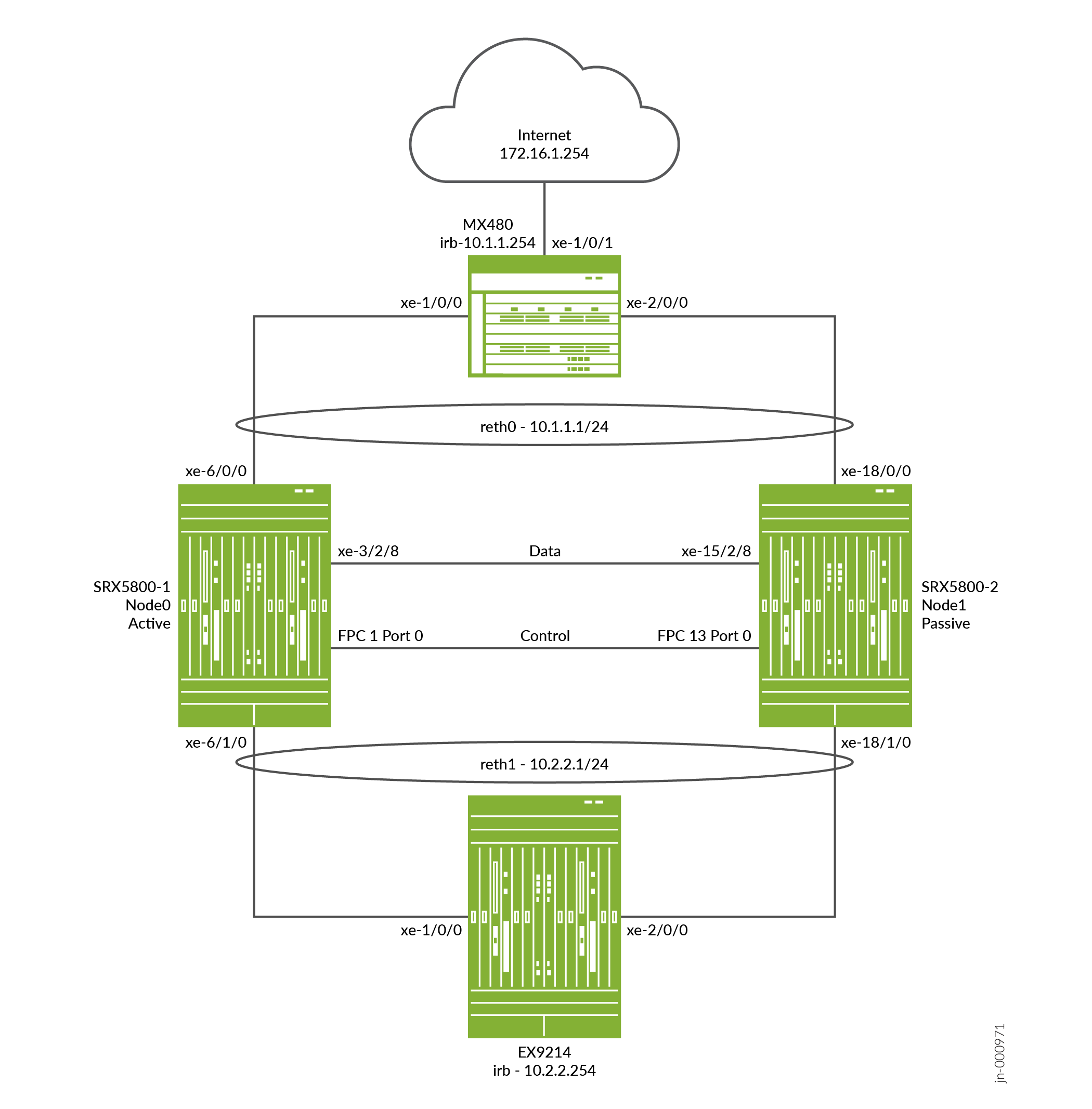
This example shows how to set up basic active/passive chassis clustering on an SRX5800 Firewalls.
Requirements
Before you begin:
-
You need two SRX5800 Firewalls with identical hardware configurations, and optionally one MX480 edge router, and one EX9214 Ethernet Switch for sending end to end data traffic.
-
Physically connect the two devices (back-to-back for the fabric and control ports) and ensure that they are the same models.
-
Before the cluster is formed, you must configure control ports for each device, as well as assign a cluster ID and node ID to each device, and then reboot. When the system boots, both the nodes come up as a cluster.
Control port configuration is required for SRX5400, SRX5600, and SRX5800 firewalls.
The two devices now operate as a single cluster. From this point onward, configuration changes made on the cluster are automatically synchronized between both nodes, allowing them to function as one unified device.
Overview
This example shows how to set up basic active/passive chassis clustering on an SRX Series Firewall. The basic active/passive example is the most common type of chassis cluster.
The basic active/passive chassis cluster consists of two devices:
-
One device actively provides routing, firewall, NAT, VPN, and security services, along with maintaining control of the chassis cluster.
-
The other device passively maintains its state for cluster failover capabilities in case the active device becomes inactive.
This active/passive mode example for the SRX5800 Firewall does not describe in detail miscellaneous configurations such as how to configure NAT, security policies, or VPNs. They are essentially the same as they would be for standalone configurations. However, if you are performing proxy ARP in chassis cluster configurations, you must apply the proxy ARP configurations to the reth interfaces rather than the member interfaces because the RETH interfaces hold the logical configurations. See Configuring Proxy ARP for NAT (CLI Procedure). You can also configure separate logical interface configurations using VLANs and trunked interfaces in the SRX5800 Firewall. These configurations are similar to the standalone implementations using VLANs and trunked interfaces.
Figure 2 shows the topology used in this example.
Configuration
Configure the Control Ports and Enabling Cluster Mode
CLI Quick Configuration
To quickly configure this example, copy the following commands, paste them
into a text file, remove any line breaks, change any details necessary to
match your network configuration, copy and paste the commands into the CLI
at the [edit] hierarchy level, and then enter
commit from configuration mode.
On {primary:node0}
[edit]
set groups node0 system host-name hostA
set groups node0 system backup-router 10.52.63.254
set groups node0 system backup-router destination 10.0.0.0/8
set groups node0 interfaces fxp0 unit 0 family inet address 10.52.43.57/19
set groups node1 system host-name hostB
set groups node1 system backup-router 10.52.63.254
set groups node1 system backup-router destination 10.0.0.0/8
set groups node1 interfaces fxp0 unit 0 family inet address 10.52.52.27/19
set apply-groups “${node}”
set chassis cluster control-ports fpc 1 port 0
set chassis cluster control-ports fpc 13 port 0
set chassis cluster control-link-recovery
set chassis cluster reth-count 2
set chassis cluster redundancy-group 0 node 0 priority 254
set chassis cluster redundancy-group 0 node 1 priority 1
set chassis cluster redundancy-group 1 node 0 priority 254
set chassis cluster redundancy-group 1 node 1 priority 1
set chassis cluster redundancy-group 1 interface-monitor xe-6/0/0 weight 255
set chassis cluster redundancy-group 1 interface-monitor xe-18/0/0 weight 255
set chassis cluster redundancy-group 1 interface-monitor xe-6/1/0 weight 255
set chassis cluster redundancy-group 1 interface-monitor xe-18/1/0 weight 255
set security policies from-zone trust to-zone untrust policy allow match source-address any
set security policies from-zone trust to-zone untrust policy allow match destination-address any
set security policies from-zone trust to-zone untrust policy allow match application any
set security policies from-zone trust to-zone untrust policy allow then permit
set security policies from-zone untrust to-zone trust policy allow match source-address any
set security policies from-zone untrust to-zone trust policy allow match destination-address any


set security policies from-zone untrust to-zone trust policy allow match application any
set security policies from-zone untrust to-zone trust policy allow then permit
set security zones security-zone trust host-inbound-traffic system-services ping
set security zones security-zone trust interfaces reth1.50
set security zones security-zone untrust host-inbound-traffic system-services ping
set security zones security-zone untrust interfaces reth0.51
set interfaces xe-6/1/0 gigether-options redundant-parent reth1
set interfaces xe-6/0/0 gigether-options redundant-parent reth0
set interfaces xe-18/1/0 gigether-options redundant-parent reth1
set interfaces xe-18/0/0 gigether-options redundant-parent reth0
set interfaces fab0 fabric-options member-interfaces xe-3/2/8
set interfaces fab1 fabric-options member-interfaces xe-15/2/8
set interfaces reth0 vlan-tagging
set interfaces reth0 redundant-ether-options redundancy-group 1
set interfaces reth0 unit 51 vlan-id 51
set interfaces reth0 unit 51 family inet address 10.1.1.1/24
set interfaces reth1 vlan-tagging
set interfaces reth1 redundant-ether-options redundancy-group 1
set interfaces reth1 unit 50 vlan-id 50
set interfaces reth1 unit 50 family inet address 10.2.2.1/24
set routing-options static route 10.0.0.0/8 next-hop 10.52.63.254
set routing-options static route 172.16.1.0/24 next-hop 10.1.1.254
(Optional) To quickly configure an EX9214 Core Switch, copy the following commands, paste them
into a text file, remove any line breaks, change any details necessary to
match your network configuration, copy and paste the commands into the CLI
at the [edit] hierarchy level, and then enter
commit from configuration mode.
On EX device
[edit]
set interfaces xe-1/0/0 unit 0 family ethernet-switching interface-mode trunk
set interfaces xe-1/0/0 unit 0 family ethernet-switching vlan members v50
set interfaces xe-2/0/0 unit 0 family ethernet-switching interface-mode trunk
set interfaces xe-2/0/0 unit 0 family ethernet-switching vlan members v50
set interfaces irb unit 50 family inet address 10.2.2.254/24
set routing-options static route 10.1.1.0/24 next-hop 10.2.2.1
set routing-options static route 172.16.1.0/24 next-hop 10.2.2.1
set vlans v50 vlan-id 50
set vlans v50 l3-interface irb.50
(Optional)To quickly configure an MX480 edge router, copy the following commands, paste them into
a text file, remove any line breaks, change any details necessary to match
your network configuration, copy and paste the commands into the CLI at the
[edit] hierarchy level, and then enter
commit from configuration mode.
On MX device
[edit]
set interfaces xe-1/0/0 encapsulation ethernet-bridge
set interfaces xe-1/0/0 unit 0 family bridge interface-mode trunk
set interfaces xe-1/0/0 unit 0 family bridge vlan-id 51
set interfaces xe-1/0/1 unit 0 family inet address 172.16.1.1/24
set interfaces xe-2/0/0 encapsulation ethernet-bridge
set interfaces xe-2/0/0 unit 0 family bridge interface-mode trunk
set interfaces xe-2/0/0 unit 0 family bridge vlan-id 51
set interfaces irb unit 0 family inet address 10.1.1.254/24
set routing-options static route 10.2.2.0/24 next-hop 10.1.1.1
set bridge-domains v51 domain-type bridge
set bridge-domains v51 vlan-id 51
set bridge-domains v51 routing-interface irb.0
Step-by-Step Procedure
The following example requires you to navigate various levels in the configuration hierarchy.
To configure a chassis cluster on an SRX Series Firewall:
In cluster mode, the configuration is synchronized over the control link
between the nodes when you execute a commit command. All
commands are applied to both nodes regardless of from which device the
command is configured.
-
Because the SRX5000 Firewall chassis cluster configuration is contained within a single common configuration, to assign some elements of the configuration to a specific member only, you must use the Junos OS node-specific configuration method called groups. The
set apply-groups ${node}command uses the node variable to define how the groups are applied to the nodes; each node recognizes its number and accepts the configuration accordingly. You must also configure out-of-band management on the fxp0 interface of the SRX5000 Firewall using separate IP addresses for the individual control planes of the cluster.Configuring the backup router destination address as x.x.x.0/0 is not allowed.
user@hostA# set groups node0 system host-name hostA
user@hostA# set groups node0 system backup-router 10.52.63.254
user@hostA# set groups node0 system backup-router destination 10.0.0.0/8
user@hostA# set groups node0 interfaces fxp0 unit 0 family inet address 10.52.43.57/19
user@hostB# set groups node1 system host-name hostB
user@hostB# set groups node1 system backup-router 10.52.63.254
user@hostB# set groups node1 system backup-router destination 10.0.0.0/8
user@hostB# set groups node1 interfaces fxp0 unit 0 family inet address 10.52.52.27/19
The above groups node0 and node1 configuration is committed, but not applied. Once the device is up in cluster, these commands are applied using
set apply-groups “${node}”. -
Use the following commands to configure the node 0, which is primary. The node 1 is unreachable till the node configuration is committed. The node 0 will automatically sync the configuration through the control port to node 1 and it is not required to explicitly configure node 1.
user@hostA# set apply-groups “${node}” -
Configure the control port for each device, and commit the configuration.
Ensure to have the physical control link connection between the SPC cards on both the nodes as per the configuration.
The control ports are derived based on the SPC location in the chassis and offset value is based on the platform. In the below example the SPC is present in revenue slot 1 and because offset of SRX5800 is 12, the control ports are 1, 13. You can view the Offset value for particular platform using
“jwhoami -c”command in shell mode.You must enter the following commands on both devices. For example:-
On node 0:
user@hostA# set chassis cluster control-ports fpc 1 port 0
user@hostA# set chassis cluster control-ports fpc 13 port 0
user@hostA# commit
-
On node 1:
user@hostB# set chassis cluster control-ports fpc 1 port 0
user@hostB# set chassis cluster control-ports fpc 13 port 0
user@hostB# commit
-
-
Set the two devices to cluster mode. A reboot is required to enter into cluster mode after the cluster ID and node ID are set. You can cause the system to boot automatically by including the
rebootparameter in the CLI command line. You must enter the operational mode commands on both devices. For example:-
On node 0:
user@hostA> set chassis cluster cluster-id 1 node 0 reboot
-
On node 1:
user@hostB> set chassis cluster cluster-id 1 node 1 reboot
The cluster ID must be the same on both devices in a cluster, but the node ID must be different because one device is node 0 and the other device is node 1. The range for the cluster ID is 1 through 255. Setting a cluster ID to 0 is equivalent to disabling a cluster. But it is recommended to use
set chassis cluster
                                    disable
to break the nodes from cluster. -
-
Configure redundancy groups for chassis clustering. Each node has interfaces in a redundancy group where interfaces are active in active redundancy groups (multiple active interfaces can exist in one redundancy group). Redundancy group 0 controls the control plane and redundancy group 1+ controls the data plane and includes the data plane ports. For this active/passive mode example, only one chassis cluster member is active at a time so you need to define redundancy groups 0 and 1 only. Besides redundancy groups, you must also define:
-
Redundant Ethernet groups—Configure how many redundant Ethernet interfaces (member links) will be active on the device so that the system can allocate the appropriate resources for it.
-
Priority for control plane and data plane—Define which device has priority (for chassis cluster, high priority is preferred) for the control plane, and which device is preferred to be active for the data plane.
-
In active/passive or active/active mode, the control plane (redundancy group 0) can be active on a chassis different from the data plane (redundancy group 1+ and groups) chassis. However, for this example we recommend having both the control and data plane active on the same chassis member. When traffic passes through the fabric link to go to another member node, latency is introduced (z line mode traffic).
-
On SRX Series Firewalls (SRX5000 line), the IPsec VPN is not supported in active/active chassis cluster configuration (that is, when there are multiple RG1+ redundancy groups) in Z mode.
-
user@hostA# set chassis cluster reth-count 2
user@hostA# set chassis cluster redundancy-group 1 node 0 priority 254
user@hostA# set chassis cluster redundancy-group 1 node 1 priority 1
user@hostA# set chassis cluster redundancy-group 0 node 0 priority 254
user@hostA# set chassis cluster redundancy-group 0 node 1 priority 1
-
-
Configure the fabric (data) ports of the cluster that are used to pass RTOs in active/passive mode. For this example, use one of the revenue ports. Define two fabric interfaces, one on each chassis, to connect together.
Configure the data interfaces on the platform so that in the event of a data plane failover, the other chassis cluster member can take over the connection seamlessly. Seamless transition to a new active node will occur with data plane failover. In case of control plane failover, all the daemons are restarted on the new node thus enabling a graceful restart to avoid losing neighborship with peers (ospf, bgp). This promotes a seamless transition to the new node without any packet loss.
You must define the following items:
-
Define the membership information of the member interfaces to the reth interface.
-
Define which redundancy group the reth interface is a member of. For this active/passive example, it is always 1.
-
Define reth interface information such as the IP address of the interface.
{primary:node0}[edit]user@hostA# set interfaces xe-6/1/0 gigether-options redundant-parent reth1 user@hostA# set interfaces xe-6/0/0 gigether-options redundant-parent reth0 user@hostA# set interfaces xe-18/1/0 gigether-options redundant-parent reth1 user@hostA# set interfaces xe-18/0/0 gigether-options redundant-parent reth0 user@hostA# set interfaces reth0 vlan-tagging user@hostA# set interfaces reth0 redundant-ether-options redundancy-group 1 user@hostA# set interfaces reth0 unit 51 vlan-id 51 user@hostA# set interfaces reth0 unit 51 family inet address 10.1.1.1/24 user@hostA# set interfaces reth1 vlan-tagging user@hostA# set interfaces reth1 redundant-ether-options redundancy-group 1 user@hostA# set interfaces reth1 unit 50 vlan-id 50 user@hostA# set interfaces reth1 unit 50 family inet address 10.2.2.1/24 user@hostA# set interfaces fab0 fabric-options member-interfaces xe-3/2/8 user@hostA# set interfaces fab1 fabric-options member-interfaces xe-15/2/8 -
-
(Optional) Configure the chassis cluster behavior in case of a failure. For the SRX5800 Firewall, the failover threshold is set at 255. You can alter the weights to determine the impact on the chassis failover. You must also configure control link recovery. The recovery automatically causes the secondary node to reboot should the control link fail, and then come back online. Enter these commands on node 0.
{primary:node0}[edit]user@hostA# set chassis cluster redundancy-group 1 interface-monitor xe-6/0/0 weight 255 user@hostA# set chassis cluster redundancy-group 1 interface-monitor xe-6/1/0 weight 255 user@hostA# set chassis cluster redundancy-group 1 interface-monitor xe-18/0/0 weight 255 user@hostA# set chassis cluster redundancy-group 1 interface-monitor xe-18/1/0 weight 255 user@hostA# set chassis cluster control-link-recoveryThis step completes the chassis cluster configuration part of the active/passive mode example for the SRX5800 Firewall. The rest of this procedure describes how to configure the zone, virtual router, routing, EX9214 Core Switch, and MX480 Edge Router to complete the deployment scenario.
-
(Optional) Configure and connect the reth interfaces to the appropriate zones and virtual routers. For this example, leave the reth0 and reth1 interfaces in the default virtual router inet.0, which does not require any additional configuration.
{primary:node0}[edit]user@hostA# set security zones security-zone trust host-inbound-traffic system-services ping user@hostA# set security zones security-zone trust interfaces reth1.50 user@hostA# set security zones security-zone untrust host-inbound-traffic system-services ping user@hostA# set security zones security-zone untrust interfaces reth0.51 -
Create the security policy to permit traffic from the trust zone to the untrust zone.
user@hostA# set security policies from-zone trust to-zone untrust policy allow match source-address any user@hostA# set security policies from-zone trust to-zone untrust policy allow match destination-address any user@hostA# set security policies from-zone trust to-zone untrust policy allow match application any user@hostA# set security policies from-zone trust to-zone untrust policy allow then permit user@hostA# set security policies from-zone untrust to-zone trust policy allow match source-address any user@hostA# set security policies from-zone untrust to-zone trust policy allow match destination-address any user@hostA# set security policies from-zone untrust to-zone trust policy allow match application any user@hostA# set security policies from-zone untrust to-zone trust policy allow then permit -
(Optional) For the EX9214 Ethernet Switch, the following commands provide only an outline of the applicable configuration as it pertains to this active/passive mode example for the SRX5800 Firewall; most notably the VLANs, routing, and interface configuration.
[edit]user@switch# set interfaces xe-1/0/0 unit 0 family ethernet-switching interface-mode trunk user@switch# set interfaces xe-1/0/0 unit 0 family ethernet-switching vlan members v50 user@switch# set interfaces xe-2/0/0 unit 0 family ethernet-switching interface-mode trunk user@switch# set interfaces xe-2/0/0 unit 0 family ethernet-switching vlan members v50 user@switch# set interfaces irb unit 50 family inet address 10.2.2.254/24 user@switch# set routing-options static route 10.1.1.0/24 next-hop 10.2.2.1 user@switch# set routing-options static route 172.16.1.0/24 next-hop 10.2.2.1 user@switch# set vlans v50 vlan-id 50 user@switch# set vlans v50 l3-interface irb.50 -
(Optional) For the MX480 edge router, the following commands provide only an outline of the applicable configuration as it pertains to this active/passive mode example for the SRX5800 Firewall; most notably you must use an IRB interface within a virtual switch instance on the switch.
[edit]user@router# set interfaces xe-1/0/0 encapsulation ethernet-bridge user@router# set interfaces xe-1/0/0 unit 0 family bridge interface-mode trunk user@router# set interfaces xe-1/0/0 unit 0 family bridge vlan-id 51 user@router# set interfaces xe-1/0/1 unit 0 family inet address 172.16.1.1/24 user@router# set interfaces xe-2/0/0 encapsulation ethernet-bridge user@router# set interfaces xe-2/0/0 unit 0 family bridge interface-mode trunk user@router# set interfaces xe-2/0/0 unit 0 family bridge vlan-id 51 user@router# set interfaces irb unit 0 family inet address 10.1.1.254/24 user@router# set routing-options static route 10.2.2.0/24 next-hop 10.1.1.1 user@router# set bridge-domains v51 domain-type bridge user@router# set bridge-domains v51 vlan-id 51 user@router# set bridge-domains v51 routing-interface irb.0
Verification
Confirm that the configuration is working properly.
- Verify Chassis Cluster Status
- Verify Chassis Cluster Interfaces
- Verify Chassis Cluster Statistics
- Verify Chassis Cluster Control Plane Statistics
- Verify Chassis Cluster Data Plane Statistics
- Verify Ping from EX Device
- Verify Chassis Cluster Redundancy Group Status
- Troubleshooting with Logs
Verify Chassis Cluster Status
Purpose
Verify the chassis cluster status, failover status, and redundancy group information.
Action
From operational mode, enter the show chassis cluster status
command.
{primary:node0}
user@hostA> show chassis cluster status
Monitor Failure codes:
    CS  Cold Sync monitoring        FL  Fabric Connection monitoring
    GR  GRES monitoring             HW  Hardware monitoring
    IF  Interface monitoring        IP  IP monitoring
    LB  Loopback monitoring         MB  Mbuf monitoring
    NH  Nexthop monitoring          NP  NPC monitoring
    SP  SPU monitoring              SM  Schedule monitoring
    CF  Config Sync monitoring      RE  Relinquish monitoring
    IS  IRQ storm

Cluster ID: 1
Node   Priority Status               Preempt Manual   Monitor-failures

Redundancy group: 0 , Failover count: 1
node0  254      primary              no      no       None
node1  1        secondary            no      no       None

Redundancy group: 1 , Failover count: 1
node0  254      primary              no      no       None
node1  1        secondary            no      no       None
Verify Chassis Cluster Interfaces
Purpose
Verify information about chassis cluster interfaces.
Action
From operational mode, enter the show chassis cluster
interfaces command.
{primary:node0}
user@hostA> show chassis cluster interfaces
Control link status: Up

Control interfaces:
    Index   Interface   Monitored-Status   Internal-SA   Security
    0       em0         Up                 Disabled      Disabled

Fabric link status: Up

Fabric interfaces:
    Name    Child-interface    Status                    Security
                               (Physical/Monitored)
    fab0    xe-3/2/8           Up   / Up                 Disabled
    fab0
    fab1    xe-15/2/8           Up   / Up                 Disabled
    fab1

Redundant-ethernet Information:
    Name         Status      Redundancy-group
    reth0        Up          1
    reth1        Up          1

Redundant-pseudo-interface Information:
    Name         Status      Redundancy-group
    lo0          Up          0

Interface Monitoring:
    Interface         Weight    Status                    Redundancy-group
                                (Physical/Monitored)
    xe-18/1/0          255       Up  /  Up                 1
    xe-6/1/0          255       Up  /  Up                 1
    xe-18/0/0          255       Up  /  Up                 1
    xe-6/0/0          255       Up  /  Up                 1
Verify Chassis Cluster Statistics
Purpose
Verify information about chassis cluster services and control link statistics (heartbeats sent and received), fabric link statistics (probes sent and received), and the number of RTOs sent and received for services.
Action
From operational mode, enter the show chassis cluster
statistics command.
{primary:node0}
user@hostA> show chassis cluster statistics

Control link statistics:
    Control link 0:
        Heartbeat packets sent: 229414
        Heartbeat packets received: 229385
        Heartbeat packet errors: 0
Fabric link statistics:
    Child link 0
        Probes sent: 459691
        Probes received: 459679
    Child link 1
        Probes sent: 0
        Probes received: 0
Services Synchronized:
    Service name                              RTOs sent    RTOs received
    Translation context                       0            0
    Incoming NAT                              0            0
    Resource manager                          0            0
    DS-LITE create                            0            0
    Session create                            0            0
    IPv6 session create                       0            0
    IPv4/6 session RTO ACK                    0            0
    Session close                             0            0
    IPv6 session close                        0            0
    Session change                            0            0
    IPv6 session change                       0            0
    ALG Support Library                       0            0
    Gate create                               0            0
    Session ageout refresh requests           0            0
    IPv6 session ageout refresh requests      0            0
    Session ageout refresh replies            0            0
    IPv6 session ageout refresh replies       0            0
    IPSec VPN                                 0            0
    Firewall user authentication              0            0
    MGCP ALG                                  0            0
    H323 ALG                                  0            0
    SIP ALG                                   0            0
    SCCP ALG                                  0            0
    PPTP ALG                                  0            0
    JSF PPTP ALG                              0            0
    RPC ALG                                   0            0
    RTSP ALG                                  0            0
    RAS ALG                                   0            0
    MAC address learning                      0            0
    GPRS GTP                                  0            0
    GPRS SCTP                                 0            0
    GPRS FRAMEWORK                            0            0
    JSF RTSP ALG                              0            0
    JSF SUNRPC MAP                            0            0
    JSF MSRPC MAP                             0            0
    DS-LITE delete                            0            0
    JSF SLB                                   0            0
    APPID                                     0            0
    JSF MGCP MAP                              0            0
    JSF H323 ALG                              0            0
    JSF RAS ALG                               0            0
    JSF SCCP MAP                              0            0
    JSF SIP MAP                               0            0
    PST_NAT_CREATE                            0            0
    PST_NAT_CLOSE                             0            0
    PST_NAT_UPDATE                            0            0
    JSF TCP STACK                             0            0
    JSF IKE ALG                               0            0

Packet stats                              Pkts sent    Pkts received
    ICD Data                                  0            0
Verify Chassis Cluster Control Plane Statistics
Purpose
Verify information about chassis cluster control plane statistics (heartbeats sent and received) and the fabric link statistics (probes sent and received).
Action
From operational mode, enter the show chassis cluster control-plane
statistics command.
{primary:node0}
user@hostA> show chassis cluster control-plane statistics
Control link statistics:
    Control link 0:
        Heartbeat packets sent: 229474
        Heartbeat packets received: 229445
        Heartbeat packet errors: 0
Fabric link statistics:
    Child link 0
        Probes sent: 459809
        Probes received: 459797
    Child link 1
        Probes sent: 0
        Probes received: 0
Verify Chassis Cluster Data Plane Statistics
Purpose
Verify information about the number of RTOs sent and received for services.
Action
From operational mode, enter the show chassis cluster data-plane
statistics command.
{primary:node0}
user@hostA> show chassis cluster data-plane statistics
Services Synchronized:
    Service name                              RTOs sent    RTOs received
    Translation context                       0            0
    Incoming NAT                              0            0
    Resource manager                          0            0
    DS-LITE create                            0            0
    Session create                            0            0
    IPv6 session create                       0            0
    Session close                             0            0
    IPv6 session close                        0            0
    Session change                            0            0
    IPv6 session change                       0            0
    ALG Support Library                       0            0
    Gate create                               0            0
    Session ageout refresh requests           0            0
    IPv6 session ageout refresh requests      0            0
    Session ageout refresh replies            0            0
    IPv6 session ageout refresh replies       0            0
    IPSec VPN                                 0            0
    Firewall user authentication              0            0
    MGCP ALG                                  0            0
    H323 ALG                                  0            0
    SIP ALG                                   0            0
    SCCP ALG                                  0            0
    PPTP ALG                                  0            0
    JSF PPTP ALG                              0            0
    RPC ALG                                   0            0
    RTSP ALG                                  0            0
    RAS ALG                                   0            0
    MAC address learning                      0            0
    GPRS GTP                                  0            0
    GPRS SCTP                                 0            0
    GPRS FRAMEWORK                            0            0
    JSF RTSP ALG                              0            0
    JSF SUNRPC MAP                            0            0
    JSF MSRPC MAP                             0            0
    DS-LITE delete                            0            0
    JSF SLB                                   0            0
    APPID                                     0            0
    JSF MGCP MAP                              0            0
    JSF H323 ALG                              0            0
    JSF RAS ALG                               0            0
    JSF SCCP MAP                              0            0
    JSF SIP MAP                               0            0
    PST_NAT_CREATE                            0            0
    PST_NAT_CLOSE                             0            0
    PST_NAT_UPDATE                            0            0
    JSF TCP STACK                             0            0
    JSF IKE ALG                               0            0
Verify Ping from EX Device
Purpose
Verify the connection status from EX device.
Action
From operational mode, enter the ping 172.16.1.254 count 2
command.
user@EX9214> ping 172.16.1.254 count 2
PING 172.16.1.254 (172.16.1.254): 56 data bytes
64 bytes from 172.16.1.254: icmp_seq=0 ttl=62 time=4.599 ms
64 bytes from 172.16.1.254: icmp_seq=1 ttl=62 time=3.192 ms

--- 172.16.1.254 ping statistics ---
2 packets transmitted, 2 packets received, 0% packet loss
round-trip min/avg/max/stddev = 3.192/3.896/4.599/0.704 ms
Verify Chassis Cluster Redundancy Group Status
Purpose
Verify the state and priority of both nodes in a cluster and information about whether the primary node has been preempted or whether there has been a manual failover.
Action
From operational mode, enter the chassis cluster status
redundancy-group command.
{primary:node0}
user@hostA> show chassis cluster status redundancy-group 1
Monitor Failure codes:
    CS  Cold Sync monitoring        FL  Fabric Connection monitoring
    GR  GRES monitoring             HW  Hardware monitoring
    IF  Interface monitoring        IP  IP monitoring
    LB  Loopback monitoring         MB  Mbuf monitoring
    NH  Nexthop monitoring          NP  NPC monitoring
    SP  SPU monitoring              SM  Schedule monitoring
    CF  Config Sync monitoring      RE  Relinquish monitoring

Cluster ID: 1
Node   Priority Status         Preempt Manual   Monitor-failures

Redundancy group: 1 , Failover count: 1
node0  254      primary        no      no       None
node1  1        secondary      no      no       None
Troubleshooting with Logs
Purpose
Use these logs to identify any chassis cluster issues. You must run these logs on both nodes.
Action
From operational mode, enter these show log commands.
user@hostA> show log jsrpd
user@hostA> show log chassisd
user@hostA> show log messages
user@hostA> show log dcd
user@hostA> show traceoptions
Example: Configuring an Active/Passive Chassis Cluster Pair (SRX1500 or SRX1600)
This example shows how to configure active/passive chassis clustering for SRX1500 or SRX1600 device.
Requirements
Before you begin:
Physically connect a pair of devices together, ensuring that they are the same models.
Create a fabric link by connecting a Gigabit Ethernet interface on one device to another Gigabit Ethernet interface on the other device.
Create a control link by connecting the control port of the two SRX1500 devices.
Connect to one of the devices using the console port. (This is the node that forms the cluster.) and set the cluster ID and node number.
user@host> set chassis cluster cluster-id 1 node 0 reboot
Connect to the other device using the console port and set the cluster ID and node number.
user@host> set chassis cluster cluster-id 1 node 1 reboot
Overview
In this example, a single device in the cluster is used to route all traffic, and the other device is used only in the event of a failure. (See Figure 3.) When a failure occurs, the backup device becomes primary and controls all forwarding.
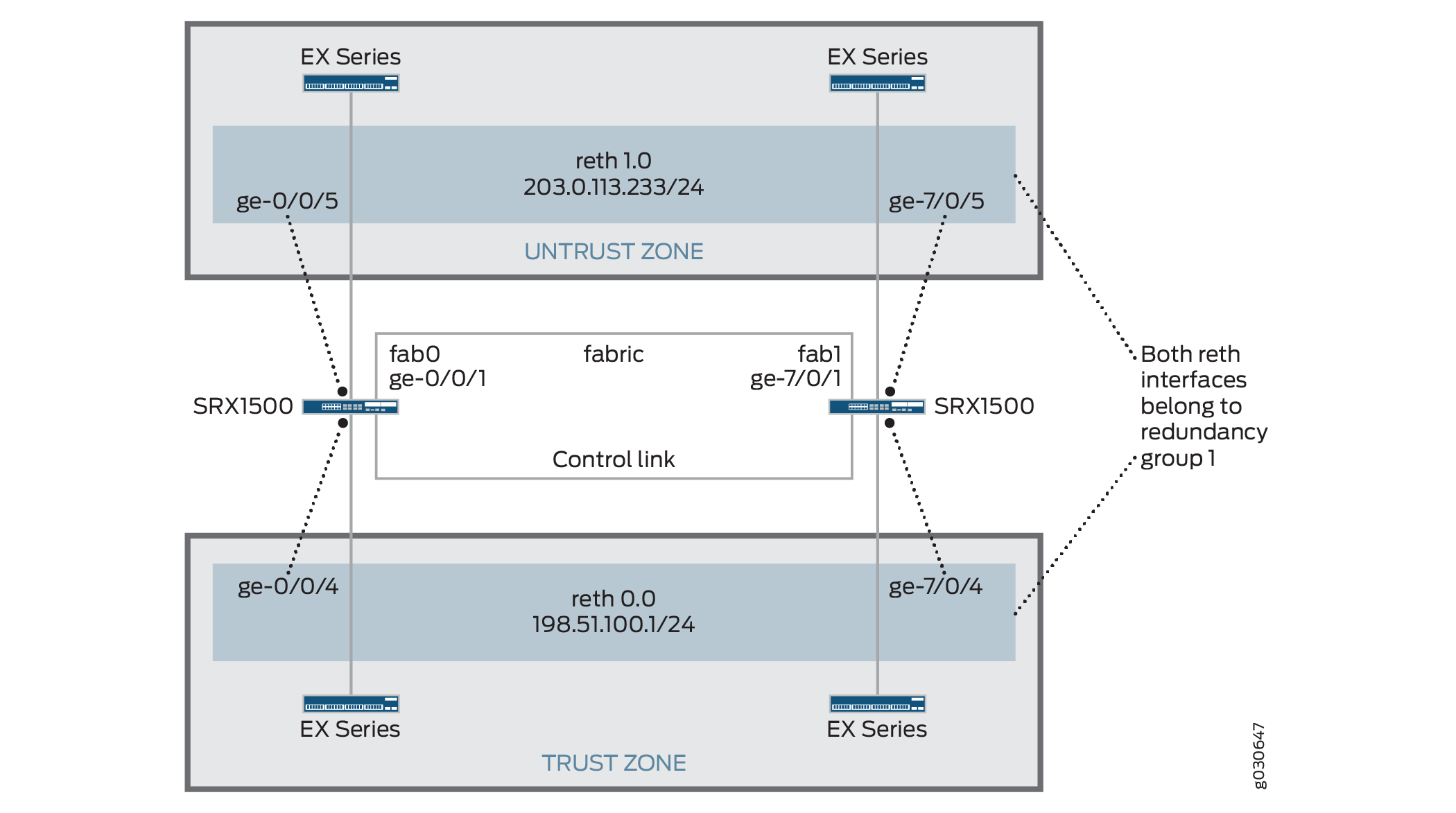
You can create an active/passive chassis cluster by configuring redundant Ethernet interfaces (reths) that are all assigned to the same redundancy group. This configuration minimizes the traffic over the fabric link because only one node in the cluster forwards traffic at any given time.
In this example, you configure group (applying the configuration
with the apply-groups command) and chassis cluster information.
Then you configure security zones and security policies. See Table 1 through Table 4.
Feature |
Name |
Configuration Parameters |
|---|---|---|
Groups |
node0 |
|
node1 |
|
Feature |
Name |
Configuration Parameters |
|---|---|---|
Fabric links |
fab0 |
Interface: ge-0/0/1 |
fab1 |
Interface: ge-7/0/1 |
|
Heartbeat interval |
– |
1000 |
Heartbeat threshold |
– |
3 |
Redundancy group |
0 |
|
1 |
|
|
Interface monitoring
|
||
Number of redundant Ethernet interfaces |
– |
2 |
Interfaces |
ge-0/0/4 |
Redundant parent: reth0 |
ge-7/0/4 |
Redundant parent: reth0 |
|
ge-0/0/5 |
Redundant parent: reth1 |
|
ge-7/0/5 |
Redundant parent: reth1 |
|
reth0 |
Redundancy group: 1 |
|
|
||
reth1 |
Redundancy group: 1 |
|
|
Name |
Configuration Parameters |
|---|---|
trust |
The reth1.0 interface is bound to this zone. |
untrust |
The reth0.0 interface is bound to this zone. |
Purpose |
Name |
Configuration Parameters |
|---|---|---|
This security policy permits traffic from the trust zone to the untrust zone. |
ANY |
|
Configuration
Procedure
CLI Quick Configuration
To quickly configure this example, copy the
following commands, paste them into a text file, remove any line breaks,
change any details necessary to match your network configuration,
copy and paste the commands into the CLI at the [edit] hierarchy
level, and then enter commit from configuration mode.
[edit]
set groups node0 system host-name srx1500-A
set groups node0 interfaces fxp0 unit 0 family inet address 192.0.2.110/24
set groups node1 system host-name srx1500-B
set groups node1 interfaces fxp0 unit 0 family inet address 192.0.2.111/24
set apply-groups “${node}”
set interfaces fab0 fabric-options member-interfaces ge-0/0/1
set interfaces fab1 fabric-options member-interfaces ge-7/0/1
set chassis cluster heartbeat-interval 1000
set chassis cluster heartbeat-threshold 3
set chassis cluster redundancy-group 0 node 0 priority 100
set chassis cluster redundancy-group 0 node 1 priority 1
set chassis cluster redundancy-group 1 node 0 priority 100
set chassis cluster redundancy-group 1 node 1 priority 1
set chassis cluster redundancy-group 1 interface-monitor ge-0/0/4 weight 255
set chassis cluster redundancy-group 1 interface-monitor ge-7/0/4 weight 255
set chassis cluster redundancy-group 1 interface-monitor ge-0/0/5 weight 255
set chassis cluster redundancy-group 1 interface-monitor ge-7/0/5 weight 255
set chassis cluster reth-count 2
set interfaces ge-0/0/5 gigether-options redundant-parent reth1
set interfaces ge-7/0/5 gigether-options redundant-parent reth1
set interfaces ge-0/0/4 gigether-options redundant-parent reth0
set interfaces ge-7/0/4 gigether-options redundant-parent reth0
set interfaces reth0 redundant-ether-options redundancy-group 1
set interfaces reth0 unit 0 family inet address 198.51.100.1/24
set interfaces reth1 redundant-ether-options redundancy-group 1
set interfaces reth1 unit 0 family inet address 203.0.113.233/24
set security zones security-zone untrust interfaces reth1.0
set security zones security-zone trust interfaces reth0.0
set security policies from-zone trust to-zone untrust policy ANY match source-address any
set security policies from-zone trust to-zone untrust policy ANY match destination-address any
set security policies from-zone trust to-zone untrust policy ANY match application any
set security policies from-zone trust to-zone untrust policy ANY then permit
Step-by-Step Procedure
To configure an active/passive chassis cluster:
Configure the management interface.
{primary:node0}[edit]
user@host# set groups node0 system host-name srx1500-A
user@host# set groups node0 interfaces fxp0 unit 0 family inet address 192.0.2.110/24
user@host# set groups node1 system host-name srx1500-B
user@host# set groups node1 interfaces fxp0 unit 0 family inet address 192.0.2.111/24
user@host# set apply-groups “${node}”
Configure the fabric interface.
{primary:node0}[edit]
user@host# set interfaces fab0 fabric-options member-interfaces ge-0/0/1
user@host# set interfaces fab1 fabric-options member-interfaces ge-7/0/1
Configure heartbeat settings.
{primary:node0}[edit]
user@host# set chassis cluster heartbeat-interval 1000
user@host# set chassis cluster heartbeat-threshold 3
Configure redundancy groups.
{primary:node0}[edit]
user@host# set chassis cluster redundancy-group 0 node 0 priority 100
user@host# set chassis cluster redundancy-group 0 node 1 priority 1
user@host# set chassis cluster redundancy-group 1 node 0 priority 100
user@host# set chassis cluster redundancy-group 1 node 1 priority 1
user@host# set chassis cluster redundancy-group 1 interface-monitor ge-0/0/4 weight 255
user@host# set chassis cluster redundancy-group 1 interface-monitor ge-7/0/4 weight 255
user@host# set chassis cluster redundancy-group 1 interface-monitor ge-0/0/5 weight 255
user@host# set chassis cluster redundancy-group 1 interface-monitor ge-7/0/5 weight 255
Configure redundant Ethernet interfaces.
{primary:node0}[edit]
user@host# set chassis cluster reth-count 2
user@host# set interfaces ge-0/0/5 gigether-options redundant-parent reth1
user@host# set interfaces ge-7/0/5 gigether-options redundant-parent reth1
user@host# set interfaces ge-0/0/4 gigether-options redundant-parent reth0
user@host# set interfaces ge-7/0/4 gigether-options redundant-parent reth0
user@host# set interfaces reth0 redundant-ether-options redundancy-group 1
user@host# set interfaces reth0 unit 0 family inet address 198.51.100.1/24
user@host# set interfaces reth1 redundant-ether-options redundancy-group 1
user@host# set interfaces reth1 unit 0 family inet address 203.0.113.233/24
Configure security zones.
{primary:node0}[edit]
user@host# set security zones security-zone untrust interfaces reth1.0
user@host# set security zones security-zone trust interfaces reth0.0
Configure security policies.
{primary:node0}[edit]
user@host# set security policies from-zone trust to-zone untrust policy ANY match source-address any
user@host# set security policies from-zone trust to-zone untrust policy ANY match destination-address any
user@host# set security policies from-zone trust to-zone untrust policy ANY match application any
user@host# set security policies from-zone trust to-zone untrust policy ANY then permit
Results
From configuration mode, confirm your configuration
by entering the show configuration command. If the output
does not display the intended configuration, repeat the configuration
instructions in this example to correct it.
For brevity, this show command output includes only
the configuration that is relevant to this example. Any other configuration
on the system has been replaced with ellipses (...).
user@host> show configuration
version x.xx.x;
groups {
    node0 {
        system {
            host-name srx1500-A;
        }
        interfaces {
            fxp0 {
                unit 0 {
                    family inet {
                        address 192.0.2.110/24;
                    }
                }
            }
        }
    }
    node1 {
        system {
            host-name srx1500-B;
            interfaces {
                fxp0 {
                    unit 0 {
                        family inet {
                            address 192.0.2.110/24;
                        }
                    }
                }
            }
        }
    }
    apply-groups "${node}";
    chassis {
        cluster {
            reth-count 2;
            heartbeat-interval 1000;
            heartbeat-threshold 3;
            redundancy-group 0 {
                node 0 priority 100;
                node 1 priority 1;
            }
            redundancy-group 1 {
                node 0 priority 100;
                node 1 priority 1;
                interface-monitor {
                    ge–0/0/4 weight 255;
                    ge–7/0/4 weight 255;
                    ge–0/0/5 weight 255;
                    ge–7/0/5 weight 255;
                }
            }
        }
    }
    interfaces {
        ge–0/0/4 {
            gigether–options {
                redundant–parent reth0;
            }
        }
        ge–7/0/4{
            gigether–options {
                redundant–parent reth0;
            }
        }
        ge–0/0/5 {
            gigether–options {
                redundant–parent reth1;
            }
        }
        ge–7/0/5 {
            gigether–options {
                redundant–parent reth1;
            }
        }
        fab0 {
            fabric–options {
                member–interfaces {
                    ge–0/0/1;
                }
            }
        }
        fab1 {
            fabric–options {
                member–interfaces {
                    ge–7/0/1;
                }
            }
        }
        reth0 {
            redundant–ether–options {
                redundancy–group 1;
            }
            unit 0 {
                family inet {
                    address 198.51.100.1/24;
                }
            }
        }
        reth1 {
            redundant–ether–options {
                redundancy–group 1;
            }
            unit 0 {
                family inet {
                    address 203.0.113.233/24;
                }
            }
        }
    }
...
security {
    zones {
        security–zone untrust {
            interfaces {
                reth1.0;
            }
        }
        security–zone trust {
            interfaces {
                reth0.0;
            }
        }
    }
    policies {
        from-zone trust to-zone untrust {
            policy ANY {
                match {
                    source-address any;
                    destination-address any;
                    application any;
                }
                then {
                    permit;
                }
            }
        }
    }
}
If you are done configuring the device, enter commit from configuration mode.
Verification
Confirm that the configuration is working properly.
- Verify Chassis Cluster Status
- Verify Chassis Cluster Interfaces
- Verify Chassis Cluster Statistics
- Verify Chassis Cluster Control Plane Statistics
- Verify Chassis Cluster Data Plane Statistics
- Verify Chassis Cluster Redundancy Group Status
- Troubleshooting with Logs
Verify Chassis Cluster Status
Purpose
Verify the chassis cluster status, failover status, and redundancy group information.
Action
From operational mode, enter the show chassis cluster
status command.
{primary:node0}
user@host> show chassis cluster status
Cluster ID: 1
Node Priority Status Preempt Manual failover
Redundancy group: 0 , Failover count: 1
node0 100 primary no no
node1 1 secondary no no
Redundancy group: 1 , Failover count: 1
node0 100 primary no no
node1 1 secondary no no
Verify Chassis Cluster Interfaces
Purpose
Verify information about chassis cluster interfaces.
Action
From operational mode, enter the show chassis cluster
interfaces command.
{primary:node0}
user@host> show chassis cluster interfaces
Control link status: Up
Control interfaces:
Index Interface Monitored-Status Security
0 em0 Up Disabled
1 em1 Down Disabled
Fabric link status: Up
Fabric interfaces:
Name Child-interface Status Security
fab0 ge-0/0/1 Up Disabled
fab0
fab1 ge-7/0/1 Up Disabled
fab1
Redundant-ethernet Information:
Name Status Redundancy-group
reth0 Up 1
reth1 Up 1
Redundant-pseudo-interface Information:
Name Status Redundancy-group
lo0 Up 1
Interface Monitoring:
Interface Weight Status Redundancy-group
ge-0/0/4 255 Up 1
ge-7/0/4 255 Up 1
ge-0/0/5 255 Up 1
ge-7/0/5 255 Up 1
Verify Chassis Cluster Statistics
Purpose
Verify information about the statistics of the different objects being synchronized, the fabric and control interface hellos, and the status of the monitored interfaces in the cluster.
Action
From operational mode, enter the show chassis cluster
statistics command.
{primary:node0}
user@host> show chassis cluster statistics
Control link statistics:
Control link 0:
Heartbeat packets sent: 2276
Heartbeat packets received: 2280
Heartbeat packets errors: 0
Fabric link statistics:
Child link 0
Probes sent: 2272
Probes received: 597
Services Synchronized:
Service name RTOs sent RTOs received
Translation context 0 0
Incoming NAT 0 0
Resource manager 6 0
Session create 161 0
Session close 148 0
Session change 0 0
Gate create 0 0
Session ageout refresh requests 0 0
Session ageout refresh replies 0 0
IPSec VPN 0 0
Firewall user authentication 0 0
MGCP ALG 0 0
H323 ALG 0 0
SIP ALG 0 0
SCCP ALG 0 0
PPTP ALG 0 0
RPC ALG 0 0
RTSP ALG 0 0
RAS ALG 0 0
MAC address learning 0 0
GPRS GTP 0 0
Verify Chassis Cluster Control Plane Statistics
Purpose
Verify information about chassis cluster control plane statistics (heartbeats sent and received) and the fabric link statistics (probes sent and received).
Action
From operational mode, enter the show chassis cluster
control-plane statistics command.
{primary:node0}
user@host> show chassis cluster control-plane statistics
Control link statistics:
Control link 0:
Heartbeat packets sent: 258689
Heartbeat packets received: 258684
Heartbeat packets errors: 0
Fabric link statistics:
Child link 0
Probes sent: 258681
Probes received: 258681
Verify Chassis Cluster Data Plane Statistics
Purpose
Verify information about the number of RTOs sent and received for services.
Action
From operational mode, enter the show chassis cluster
data-plane statistics command.
{primary:node0}
user@host> show chassis cluster data-plane statistics
Services Synchronized:
Service name RTOs sent RTOs received
Translation context 0 0
Incoming NAT 0 0
Resource manager 6 0
Session create 161 0
Session close 148 0
Session change 0 0
Gate create 0 0
Session ageout refresh requests 0 0
Session ageout refresh replies 0 0
IPSec VPN 0 0
Firewall user authentication 0 0
MGCP ALG 0 0
H323 ALG 0 0
SIP ALG 0 0
SCCP ALG 0 0
PPTP ALG 0 0
RPC ALG 0 0
RTSP ALG 0 0
RAS ALG 0 0
MAC address learning 0 0
GPRS GTP 0 0Verify Chassis Cluster Redundancy Group Status
Purpose
Verify the state and priority of both nodes in a cluster and information about whether the primary node has been preempted or whether there has been a manual failover.
Action
From operational mode, enter the chassis cluster
status redundancy-group command.
{primary:node0}
user@host> show chassis cluster status redundancy-group 1
Cluster ID: 1
Node Priority Status Preempt Manual failover
Redundancy-Group: 1, Failover count: 1
node0 100 primary no no
node1 1 secondary no no
Troubleshooting with Logs
Purpose
Use these logs to identify any chassis cluster issues. You must run these logs on both nodes.
Action
From operational mode, enter these show commands.
user@host> show log jsrpd user@host> show log chassisd user@host> show log messages user@host> show log dcd user@host> show traceoptions
Example: Configuring an Active/Passive Chassis Cluster Pair (J-Web)
Enable clustering. See Step 1 in Example: Configuring an Active/Passive Chassis Cluster Pair (CLI).
Configure the management interface. See Step 2 in Example: Configuring an Active/Passive Chassis Cluster Pair (CLI).
Configure the fabric interface. See Step 3 in Example: Configuring an Active/Passive Chassis Cluster Pair (CLI).
Configure the redundancy groups.
Select
Configure>Chassis Cluster.Enter the following information, and then click
Apply:Redundant ether-Interface Count:
2Heartbeat Interval:
1000Heartbeat Threshold:
3Nodes:
0Group Number:
0Priorities:
100
Enter the following information, and then click
Apply:Nodes:
0Group Number:
1Priorities:
1
Enter the following information, and then click
Apply:Nodes:
1Group Number:
0Priorities:
100
Configure the redundant Ethernet interfaces.
Select
Configure>Chassis Cluster.Select
ge-0/0/4.Enter
reth1in the Redundant Parent box.Click
Apply.Select
ge-7/0/4.Enter
reth1in the Redundant Parent box.Click
Apply.Select
ge-0/0/5.Enter
reth0in the Redundant Parent box.Click
Apply.Select
ge-7/0/5.Enter
reth0in the Redundant Parent box.Click
Apply.See Step 5 in Example: Configuring an Active/Passive Chassis Cluster Pair (CLI) for the last four configuration settings.
Configure the security zones. See Step 6 in Example: Configuring an Active/Passive Chassis Cluster Pair (CLI).
Configure the security policies. See Step 7 in Example: Configuring an Active/Passive Chassis Cluster Pair (CLI).
Click
OKto check your configuration and save it as a candidate configuration, then clickCommit Options>Commit.
See Also
Understand Active/Passive Chassis Cluster Deployment with an IPsec Tunnel
In this case, a single device in the cluster terminates in an IPsec tunnel and is used to process all traffic while the other device is used only in the event of a failure (see Figure 4). When a failure occurs, the backup device becomes primary and controls all forwarding.
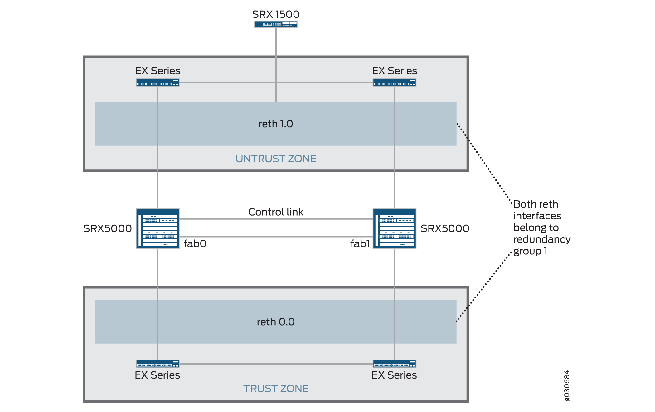
An active/passive chassis cluster can be achieved by using redundant Ethernet interfaces (reths) that are assigned to the same redundancy group. If any of the interfaces in an active group in a node fails, the group is declared inactive and all the interfaces in the group fail over to the other node.
This configuration provides a way for a site-to-site IPsec tunnel to terminate in an active/passive cluster where a redundant Ethernet interface is used as the tunnel endpoint. In the event of a failure, the redundant Ethernet interface in the backup SRX Series Firewall becomes active, forcing the tunnel to change endpoints to terminate in the new active SRX Series Firewall. Because tunnel keys and session information are synchronized between the members of the chassis cluster, a failover does not require the tunnel to be renegotiated and all established sessions are maintained.
In case of RG0 (routing engine) failure, the routing protocols need to re-establish on the new Primary node. If VPN monitoring or Dead-peer-detection is configured, and its timer expires before the routing reconverges on new RG0 Primary, then VPN tunnel will be brought down and renegotiated.
Dynamic tunnels cannot load-balance across different SPCs.
See Also
Example: Configure an Active/Passive Chassis Cluster Pair with an IPsec Tunnel
This example shows how to configure active/passive chassis clustering with an IPsec tunnel for SRX Series Firewalls.
Requirements
Before you begin:
-
Get two SRX5000 models with identical hardware configurations, one SRX1500 or SRX1600 device, and four EX Series Ethernet switches.
-
Physically connect the two devices (back-to-back for the fabric and control ports) and ensure that they are the same models. You can configure both the fabric and control ports on the SRX5000 line.
-
Set the two devices to cluster mode and reboot the devices. You must enter the following operational mode commands on both devices, for example:
-
On node 0:
user@host> set chassis cluster cluster-id 1 node 0 reboot
-
On node 1:
user@host> set chassis cluster cluster-id 1 node 1 reboot
The cluster ID is the same on both devices, but the node ID must be different because one device is node 0 and the other device is node 1. The range for the cluster ID is 1 through 255. Setting a cluster ID to 0 is equivalent to disabling a cluster.
Cluster ID greater than 15 can only be set when the fabric and control link interfaces are connected back-to-back.
-
-
Get two SRX5000 models with identical hardware configurations, one SRX1500 edge router, and four EX Series Ethernet switches.
-
Physically connect the two devices (back-to-back for the fabric and control ports) and ensure that they are the same models. You can configure both the fabric and control ports on the SRX5000 line.
From this point forward, configuration of the cluster is synchronized between the node members and the two separate devices function as one device. Member-specific configurations (such as the IP address of the management port of each member) are entered using configuration groups.
Overview
In this example, a single device in the cluster terminates in an IPsec tunnel and is used to process all traffic, and the other device is used only in the event of a failure. (See Figure 5.) When a failure occurs, the backup device becomes primary and controls all forwarding.
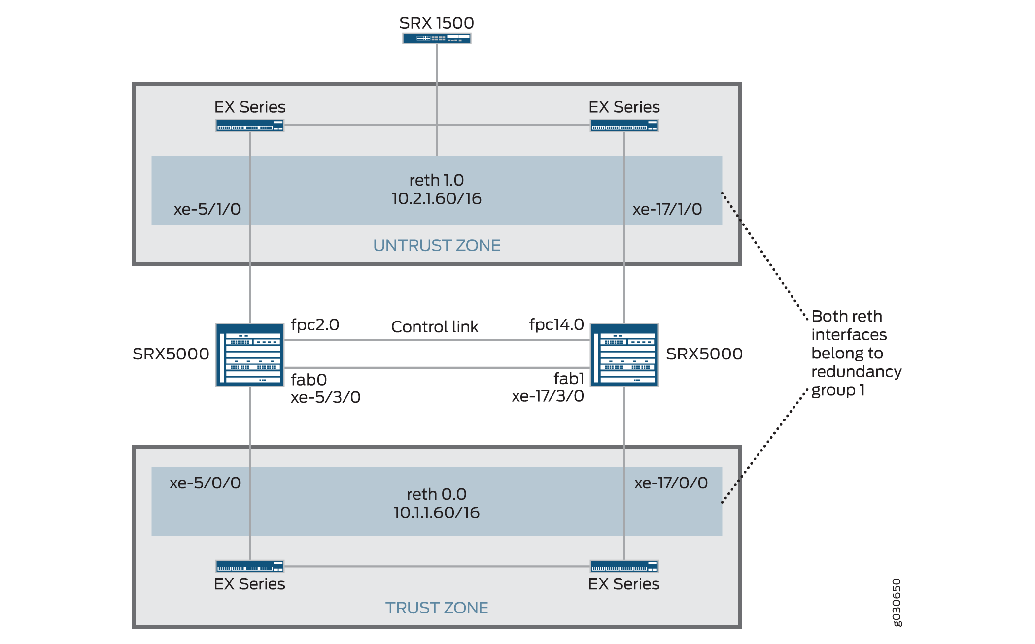
In this example, you configure group (applying the configuration
with the apply-groups command) and chassis cluster information.
Then you configure IKE, IPsec, static route, security zone, and security
policy parameters. See Table 5 through Table 11.
|
Feature |
Name |
Configuration Parameters |
|---|---|---|
|
Groups |
node0 |
|
|
node1 |
|
|
Feature |
Name |
Configuration Parameters |
|---|---|---|
|
Fabric links |
fab0 |
Interface: xe-5/3/0 |
|
fab1 |
Interface: xe-17/3/0 |
|
|
Number of redundant Ethernet interfaces |
– |
2 |
|
Heartbeat interval |
– |
1000 |
|
Heartbeat threshold |
– |
3 |
|
Redundancy group |
0 |
|
|
1 |
|
|
|
Interface monitoring
|
||
|
Interfaces |
xe-5/1/0 |
Redundant parent: reth1 |
|
xe-5/1/0 |
Redundant parent: reth1 |
|
|
xe-5/0/0 |
Redundant parent: reth0 |
|
|
xe-17/0/0 |
Redundant parent: reth0 |
|
|
reth0 |
Redundancy group: 1 |
|
|
||
|
reth1 |
Redundancy group: 1 |
|
|
||
|
st0 |
||
|
|
Feature |
Name |
Configuration Parameters |
|---|---|---|
|
Proposal |
proposal-set standard |
- |
|
Policy |
preShared |
|
|
Gateway |
SRX1500-1 |
Note:
In SRX chassis clustering, only reth and lo0 interfaces are supported for the IKE external interface configuration. Other interface types can be configured, but IPsec VPN might not work. If a lo0 logical interface is used as an IKE gateway external interface, it cannot be configured with RG0. |
|
Feature |
Name |
Configuration Parameters |
|---|---|---|
|
Proposal |
proposal-set standard |
– |
|
Policy |
std |
– |
|
VPN |
SRX1500-1 |
Note:
The manual VPN name and the site-to-site gateway name cannot be the same. |
A secure tunnel interface (st0) from st0.16000 to st0.16385 is reserved for Multinode High Availability and for HA control link encryption in Chassis Cluster. These interfaces are not user configurable interfaces. You can only use interfaces from st0.0 to st0.15999.
|
Name |
Configuration Parameters |
|---|---|
|
0.0.0.0/0 |
Next hop: 10.2.1.1 |
|
10.3.0.0/16 |
Next hop: 10.10.1.2 |
|
Name |
Configuration Parameters |
|---|---|
|
trust |
|
|
untrust |
|
|
vpn |
|
|
Purpose |
Name |
Configuration Parameters |
|---|---|---|
|
This security policy permits traffic from the trust zone to the untrust zone. |
ANY |
|
|
This security policy permits traffic from the trust zone to the vpn zone. |
vpn-any |
|
Configuration
Procedure
CLI Quick Configuration
To quickly configure this example, copy the
following commands, paste them into a text file, remove any line breaks,
change any details necessary to match your network configuration,
copy and paste the commands into the CLI at the [edit] hierarchy
level, and then enter commit from configuration mode.
{primary:node0}[edit]
set chassis cluster control-ports fpc 2 port 0
set chassis cluster control-ports fpc 14 port 0
set groups node0 system host-name SRX5800-1
set groups node0 interfaces fxp0 unit 0 family inet address 172.19.100.50/24
set groups node1 system host-name SRX5800-2
set groups node1 interfaces fxp0 unit 0 family inet address 172.19.100.51/24
set apply-groups “${node}”
set interfaces fab0 fabric-options member-interfaces xe-5/3/0
set interfaces fab1 fabric-options member-interfaces xe-17/3/0
set chassis cluster reth-count 2
set chassis cluster heartbeat-interval 1000
set chassis cluster heartbeat-threshold 3
set chassis cluster node 0
set chassis cluster node 1
set chassis cluster redundancy-group 0 node 0 priority 254
set chassis cluster redundancy-group 0 node 1 priority 1
set chassis cluster redundancy-group 1 node 0 priority 254
set chassis cluster redundancy-group 1 node 1 priority 1
set chassis cluster redundancy-group 1 preempt
set chassis cluster redundancy-group 1 interface-monitor xe-5/0/0 weight 255
set chassis cluster redundancy-group 1 interface-monitor xe-5/1/0 weight 255
set chassis cluster redundancy-group 1 interface-monitor xe-17/0/0 weight 255
set chassis cluster redundancy-group 1 interface-monitor xe-17/1/0 weight 255
set interfaces xe-5/1/0 gigether-options redundant-parent reth1
set interfaces xe-17/1/0 gigether-options redundant-parent reth1
set interfaces xe-5/0/0 gigether-options redundant-parent reth0
set interfaces xe-17/0/0 gigether-options redundant-parent reth0
set interfaces reth0 redundant-ether-options redundancy-group 1
set interfaces reth0 unit 0 family inet address 10.1.1.60/16
set interfaces reth1 redundant-ether-options redundancy-group 1
set interfaces reth1 unit 0 family inet address 10.2.1.60/16
set interfaces st0 unit 0 multipoint family inet address 10.10.1.1/30
set security ike policy preShared mode main
set security ike policy preShared proposal-set standard
set security ike policy preShared pre-shared-key ascii-text "$ABC123"## Encrypted password
set security ike gateway SRX1500-1 ike-policy preShared
set security ike gateway SRX1500-1 address 10.1.1.90
set security ike gateway SRX1500-1 external-interface reth0.0
set security ipsec policy std proposal-set standard
set security ipsec vpn SRX1500-1 bind-interface st0.0
set security ipsec vpn SRX1500-1 vpn-monitor optimized
set security ipsec vpn SRX1500-1 ike gateway SRX1500-1
set security ipsec vpn SRX1500-1 ike ipsec-policy std
set security ipsec vpn SRX1500-1 establish-tunnels immediately
set routing-options static route 0.0.0.0/0 next-hop 10.2.1.1
set routing-options static route 10.3.0.0/16 next-hop 10.10.1.2
set security zones security-zone untrust host-inbound-traffic system-services all
set security zones security-zone untrust host-inbound-traffic protocols all
set security zones security-zone untrust interfaces reth1.0
set security zones security-zone trust host-inbound-traffic system-services all
set security zones security-zone trust host-inbound-traffic protocols all
set security zones security-zone trust interfaces reth0.0
set security zones security-zone vpn host-inbound-traffic system-services all 144
set security zones security-zone vpn host-inbound-traffic protocols all
set security zones security-zone vpn interfaces st0.0
set security policies from-zone trust to-zone untrust policy ANY match source-address any
set security policies from-zone trust to-zone untrust policy ANY match destination-address any
set security policies from-zone trust to-zone untrust policy ANY match application any
set security policies from-zone trust to-zone vpn policy vpn-any then permitStep-by-Step Procedure
To configure an active/passive chassis cluster pair with an IPsec tunnel:
-
Configure control ports.
{primary:node0}[edit] user@host# set chassis cluster control-ports fpc 2 port 0 user@host# set chassis cluster control-ports fpc 14 port 0 -
Configure the management interface.
{primary:node0}[edit] user@host# set groups node0 system host-name SRX5800-1 user@host# set groups node0 interfaces fxp0 unit 0 family inet address 172.19.100.50/24 user@host#set groups node1 system host-name SRX5800-2 user@host# set groups node1 interfaces fxp0 unit 0 family inet address 172.19.100.51/24 user@host# set apply-groups “${node}” -
Configure the fabric interface.
{primary:node0}[edit] user@host# set interfaces fab0 fabric-options member-interfaces xe-5/3/0 user@host# set interfaces fab1 fabric-options member-interfaces xe-17/3/0 -
Configure redundancy groups.
{primary:node0}[edit] user@host# set chassis cluster reth-count 2 user@host# set chassis cluster heartbeat-interval 1000 user@host# set chassis cluster heartbeat-threshold 3 user@host# set chassis cluster node 0 user@host# set chassis cluster node 1 user@host# set chassis cluster redundancy-group 0 node 0 priority 254 user@host# set chassis cluster redundancy-group 0 node 1 priority 1 user@host# set chassis cluster redundancy-group 1 node 0 priority 254 user@host# set chassis cluster redundancy-group 1 node 1 priority 1 user@host# set chassis cluster redundancy-group 1 preempt user@host# set chassis cluster redundancy-group 1 interface-monitor xe-5/0/0 weight 255 user@host# set chassis cluster redundancy-group 1 interface-monitor xe-5/1/0 weight 255 user@host# set chassis cluster redundancy-group 1 interface-monitor xe-17/0/0 weight 255 user@host# set chassis cluster redundancy-group 1 interface-monitor xe-17/1/0 weight 255 -
Configure redundant Ethernet interfaces.
{primary:node0}[edit] user@host# set interfaces xe-5/1/0 gigether-options redundant-parent reth1 user@host# set interfaces xe-17/1/0 gigether-options redundant-parent reth1 user@host# set interfaces xe-5/0/0 gigether-options redundant-parent reth0 user@host# set interfaces xe-17/0/0 gigether-options redundant-parent reth0 user@host# set interfaces reth0 redundant-ether-options redundancy-group 1 user@host# set interfaces reth0 unit 0 family inet address 10.1.1.60/16 user@host# set interfaces reth1 redundant-ether-options redundancy-group 1 user@host# set interfaces reth1 unit 0 family inet address 10.2.1.60/16 -
Configure IPsec parameters.
{primary:node0}[edit] user@host# set interfaces st0 unit 0 multipoint family inet address 10.10.1.1/30 user@host# set security ike policy preShared mode main user@host# set security ike policy preShared proposal-set standard user@host# set security ike policy preShared pre-shared-key ascii-text "$ABC123"## Encrypted password user@host# set security ike gateway SRX1500-1 ike-policy preShared user@host# set security ike gateway SRX1500-1 address 10.1.1.90 user@host# set security ike gateway SRX1500-1 external-interface reth0.0 user@host# set security ipsec policy std proposal-set standard user@host# set security ipsec vpn SRX1500-1 bind-interface st0.0 user@host# set security ipsec vpn SRX1500-1 vpn-monitor optimized user@host# set security ipsec vpn SRX1500-1 ike gateway SRX1500-1 user@host# set security ipsec vpn SRX1500-1 ike ipsec-policy std user@host# set security ipsec vpn SRX1500-1 establish-tunnels immediately -
Configure static routes.
{primary:node0}[edit] user@host# set routing-options static route 0.0.0.0/0 next-hop 10.2.1.1 user@host# set routing-options static route 10.3.0.0/16 next-hop 10.10.1.2 -
Configure security zones.
{primary:node0}[edit] user@host# set security zones security-zone untrust host-inbound-traffic system-services all user@host# set security zones security-zone untrust host-inbound-traffic protocols all user@host# set security zones security-zone untrust interfaces reth1.0 user@host# set security zones security-zone trust host-inbound-traffic system-services all user@host# set security zones security-zone trust host-inbound-traffic protocols all user@host# set security zones security-zone trust interfaces reth0.0 user@host# set security zones security-zone vpn host-inbound-traffic system-services all user@host# set security zones security-zone vpn host-inbound-traffic protocols all user@host# set security zones security-zone vpn interfaces st0.0 -
Configure security policies.
{primary:node0}[edit] user@host# set security policies from-zone trust to-zone untrust policy ANY match source-address any user@host# set security policies from-zone trust to-zone untrust policy ANY match destination-address any user@host# set security policies from-zone trust to-zone untrust policy ANY match application any user@host# set security policies from-zone trust to-zone vpn policy vpn-any then permit
Results
From operational mode, confirm your configuration by
entering the show configuration command. If the output
does not display the intended configuration, repeat the configuration
instructions in this example to correct it.
For brevity, this show command output includes only
the configuration that is relevant to this example. Any other configuration
on the system has been replaced with ellipses (...).
user@host> show configuration
version x.xx.x;
groups {
node0 {
system {
host-name SRX58001;
}
interfaces {
fxp0 {
unit 0 {
family inet {
address 172.19.100.50/24;
}
}
}
}
}
node1 {
system {
host-name SRX58002;
}
interfaces {
fxp0 {
unit 0 {
family inet {
address 172.19.100.51/24;
}
}
}
}
}
}
apply-groups "${node}";
system {
root-authentication {
encrypted-password "$ABC123";
}
}
chassis {
cluster {
reth-count 2;
heartbeat-interval 1000;
heartbeat-threshold 3;
control-ports {
fpc 2 port 0;
fpc 14 port 0;
}
redundancy-group 0 {
node 0 priority 254;
node 1 priority 1;
}
redundancy-group 1 {
node 0 priority 254;
node 1 priority 1;
preempt;
interface-monitor {
xe–6/0/0 weight 255;
xe–6/1/0 weight 255;
xe–18/0/0 weight 255;
xe–18/1/0 weight 255;
}
}
}
}
interfaces {
xe–5/0/0 {
gigether–options {
redundant–parent reth0;
}
}
xe–5/1/0 {
gigether–options {
redundant–parent reth1;
}
}
xe–17/0/0 {
gigether–options {
redundant–parent reth0;
}
}
xe–17/1/0 {
gigether–options {
redundant–parent reth1;
}
}
fab0 {
fabric–options {
member–interfaces {
xe–5/3/0;
}
}
}
fab1 {
fabric–options {
member–interfaces {
xe–17/3/0;
}
}
}
reth0 {
redundant–ether–options {
redundancy–group 1;
}
unit 0 {
family inet {
address 10.1.1.60/16;
}
}
}
reth1 {
redundant–ether–options {
redundancy–group 1;
}
unit 0 {
family inet {
address 10.2.1.60/16;
}
}
}
st0 {
unit 0 {
multipoint;
family inet {
address 5.4.3.2/32;
}
}
}
}
routing–options {
static {
route 0.0.0.0/0 {
next–hop 10.2.1.1;
}
route 10.3.0.0/16 {
next–hop 10.10.1.2;
}
}
}
security {
zones {
security–zone trust {
host–inbound–traffic {
system–services {
all;
}
}
interfaces {
reth0.0;
}
}
security–zone untrust
host-inbound-traffic {
system-services {
all;
}
}
protocols {
all;
}
interfaces {
reth1.0;
}
}
security-zone vpn {
host-inbound-traffic {
system-services {
all;
}
}
protocols {
all;
}
interfaces {
st0.0;
}
}
}
policies {
from–zone trust to–zone untrust {
policy ANY {
match {
source–address any;
destination–address any;
application any;
}
then {
permit;
}
}
}
from–zone trust to–zone vpn {
policy vpn {
match {
source–address any;
destination–address any;
application any;
}
then {
permit;
}
}
}
}
}If you are done configuring the device, enter commit from configuration mode.
Verification
Confirm that the configuration is working properly.
- Verify Chassis Cluster Status
- Verify Chassis Cluster Interfaces
- Verify Chassis Cluster Statistics
- Verify Chassis Cluster Control Plane Statistics
- Verify Chassis Cluster Data Plane Statistics
- Verify Chassis Cluster Redundancy Group Status
- Troubleshooting with Logs
Verify Chassis Cluster Status
Purpose
Verify the chassis cluster status, failover status, and redundancy group information.
Action
From operational mode, enter the show chassis cluster
status command.
{primary:node0}
show chassis cluster
status
Cluster ID: 1
Node Priority Status Preempt Manual failover
Redundancy group: 0 , Failover count: 1
node0 1 primary no no
node1 254 secondary no no
Redundancy group: 1 , Failover count: 1
node0 1 primary yes no
node1 254 secondary yes no
Verify Chassis Cluster Interfaces
Purpose
Verify the chassis cluster interfaces.
Action
From operational mode, enter the show chassis cluster
interfaces command.
{primary:node0}
user@host> show chassis cluster interfaces
Control link name: fxp1
Redundant-ethernet Information:
Name Status Redundancy-group
reth0 Up 1
reth1 Up 1
Interface Monitoring:
Interface Weight Status Redundancy-group
xe-5/0/0 255 Up 1
xe-5/1/0 255 Up 1
xe-17/0/0 255 Up 1
xe-17/1/0 255 Up 1
Verify Chassis Cluster Statistics
Purpose
Verify information about chassis cluster services and control link statistics (heartbeats sent and received), fabric link statistics (probes sent and received), and the number of RTOs sent and received for services.
Action
From operational mode, enter the show chassis cluster
statistics command.
{primary:node0}
user@host> show chassis cluster statistics
Control link statistics:
Control link 0:
Heartbeat packets sent: 258689
Heartbeat packets received: 258684
Heartbeat packets errors: 0
Fabric link statistics:
Child link 0
Probes sent: 258681
Probes received: 258681
Services Synchronized:
Service name RTOs sent RTOs received
Translation context 0 0
Incoming NAT 0 0
Resource manager 6 0
Session create 161 0
Session close 148 0
Session change 0 0
Gate create 0 0
Session ageout refresh requests 0 0
Session ageout refresh replies 0 0
IPSec VPN 0 0
Firewall user authentication 0 0
MGCP ALG 0 0
H323 ALG 0 0
SIP ALG 0 0
SCCP ALG 0 0
PPTP ALG 0 0
RPC ALG 0 0
RTSP ALG 0 0
RAS ALG 0 0
MAC address learning 0 0
GPRS GTP 0 0
Verify Chassis Cluster Control Plane Statistics
Purpose
Verify information about chassis cluster control plane statistics (heartbeats sent and received) and the fabric link statistics (probes sent and received).
Action
From operational mode, enter the show chassis cluster
control-panel statistics command.
{primary:node0}
user@host> show chassis cluster control-plane statistics

Control link statistics:
    Control link 0:
        Heartbeat packets sent: 258689
        Heartbeat packets received: 258684
        Heartbeat packets errors: 0
Fabric link statistics:
    Child link 0
        Probes sent: 258681
        Probes received: 258681
Verify Chassis Cluster Data Plane Statistics
Purpose
Verify information about the number of RTOs sent and received for services.
Action
From operational mode, enter the show chassis cluster
data-plane statistics command.
{primary:node0}
user@host> show chassis cluster data-plane statistics

Services Synchronized:
    Service name                              RTOs sent    RTOs received
    Translation context                       0            0
    Incoming NAT                              0            0
    Resource manager                          6            0
    Session create                            161          0
    Session close                             148          0
    Session change                            0            0
    Gate create                               0            0
    Session ageout refresh requests           0            0
    Session ageout refresh replies            0            0
    IPSec VPN                                 0            0
    Firewall user authentication              0            0
    MGCP ALG                                  0            0
    H323 ALG                                  0            0
    SIP ALG                                   0            0
    SCCP ALG                                  0            0
    PPTP ALG                                  0            0
    RPC ALG                                   0            0
    RTSP ALG                                  0            0
    RAS ALG                                   0            0
    MAC address learning                      0            0
    GPRS GTP                                  0            0
Verify Chassis Cluster Redundancy Group Status
Purpose
Verify the state and priority of both nodes in a cluster and information about whether the primary node has been preempted or whether there has been a manual failover.
Action
From operational mode, enter the chassis cluster
status redundancy-group command.
{primary:node0}
user@host> show chassis cluster status redundancy-group 1
Cluster ID: 1
Node Priority Status Preempt Manual failover
Redundancy-Group: 1, Failover count: 1
node0 0 primary yes no
node1 254 secondary yes noTroubleshooting with Logs
Purpose
Use these logs to identify any chassis cluster issues. You must run these logs on both nodes.
Action
From operational mode, enter these show commands.
user@host> show log jsrpd
user@host> show log chassisd
user@host> show log messages
user@host> show log dcd
user@host> show traceoptions
Example: Configure an Active/Passive Chassis Cluster Pair with an IPsec Tunnel (J-Web)
Enable clusters. See Step 1 in Example: Configuring an Active/Passive Chassis Cluster Pair with an IPsec Tunnel.
Configure the management interface. See Step 2 in Example: Configuring an Active/Passive Chassis Cluster Pair with an IPsec Tunnel.
Configure the fabric interface. See Step 3 in Example: Configuring an Active/Passive Chassis Cluster Pair with an IPsec Tunnel.
Configure the redundancy groups.
Select
Configure>System Properties>Chassis Cluster.Enter the following information, and then click
Apply:Redundant ether-Interfaces Count:
2Heartbeat Interval:
1000Heartbeat Threshold:
3Nodes:
0Group Number:
0Priorities:
254
Enter the following information, and then click
Apply:Nodes:
0Group Number:
1Priorities:
254
Enter the following information, and then click
Apply:Nodes:
1Group Number:
0Priorities:
1
Enter the following information, and then click
Apply:Nodes:
1Group Number:
1Priorities:
1Preempt: Select the check box.
Interface Monitor—Interface:
xe-5/0/0Interface Monitor—Weight:
255Interface Monitor—Interface:
xe-5/1/0Interface Monitor—Weight:
255Interface Monitor—Interface:
xe-17/0/0Interface Monitor—Weight:
255Interface Monitor—Interface:
xe-17/1/0Interface Monitor—Weight:
255
Configure the redundant Ethernet interfaces.
Select
Configure>System Properties>Chassis Cluster.Select
xe-5/1/0.Enter
reth1in the Redundant Parent box.Click
Apply.Select
xe-17/1/0.Enter
reth1in the Redundant Parent box.Click
Apply.Select
xe-5/0/0.Enter
reth0in the Redundant Parent box.Click
Apply.Select
xe-17/0/0.Enter
reth0in the Redundant Parent box.Click
Apply.See Step 5 in Example: Configuring an Active/Passive Chassis Cluster Pair with an IPsec Tunnel.
Configure the IPsec configuration. See Step 6 in Example: Configuring an Active/Passive Chassis Cluster Pair with an IPsec Tunnel.
Configure the static routes .
Select
Configure>Routing>Static Routing.Click
Add.Enter the following information, and then click
Apply:Static Route Address:
0.0.0.0/0Next-Hop Addresses:
10.2.1.1
Enter the following information, and then click
Apply:Static Route Address:
10.3.0.0/16Next-Hop Addresses:
10.10.1.2
Configure the security zones. See Step 8 in Example: Configuring an Active/Passive Chassis Cluster Pair with an IPsec Tunnel.
Configure the security policies. See Step 9 in Example: Configuring an Active/Passive Chassis Cluster Pair with an IPsec Tunnel.
Click
OKto check your configuration and save it as a candidate configuration, then clickCommit Options>Commit.