Troubleshooting BGP Sessions
Checklist for Verifying the BGP Protocol and Peers
Purpose
Table 1 provides links and commands for verifying whether the Border Gateway Protocol (BGP) is configured correctly on a Juniper Networks router in your network, the internal Border Gateway Protocol (IBGP) and exterior Border Gateway Protocol (EBGP) sessions are properly established, the external routes are advertised and received correctly, and the BGP path selection process is working properly.
Action
Tasks |
Command or Action |
|---|---|
| Verify BGP Peers | |
|
|
|
|
|
|
|
|
| Examine BGP Routes and Route Selection | |
|
|
|
|
|
|
|
|
| Examine Routes in the Forwarding Table |
|
Verify BGP Peers
Purpose
Assuming that all the routers are correctly configured for BGP, you can verify if IBGP and EBGP sessions are properly established, external routes are advertised and received correctly, and the BGP path selection process is working properly.
Figure 1 illustrates an example BGP network topology used in this topic.
The network consists of two directly connected ASs consisting
of external and internal peers. The external peers are directly connected
through a shared interface and are running EBGP. The internal peers
are connected through their loopback (lo0) interfaces through
IBGP. AS 65001 is running OSPF and AS 65002 is running IS-IS as its
underlying IGP. IBGP routers do not have to be directly connected,
the underlying IGP allows neighbors to reach one another.
The two routers in AS 65001 each contain one EBGP link to AS
65002 (R2 and R4) over which they announce aggregated
prefixes: 100.100.1.0, 100.100.2.0, 100.100.3.0, and 100.100.4.0. Also, R1 and R5 are injecting multiple exit discriminator (MED) values of 5 and
10, respectively, for some routes.
The internal routers in both ASs are using a full mesh IBGP
topology. A full mesh is required because the networks are not using
confederations or route reflectors, so any routes learned through
IBGP are not distributed to other internal neighbors. For example,
when R3 learns a route from R2, R3 does not distribute that route to R6 because the route
is learned through IBGP, so R6 must have a direct BGP connection
to R2 to learn the route.
In a full mesh topology, only the border router receiving external BGP information distributes that information to other routers within its AS. The receiving router does not redistribute that information to other IBGP routers in its own AS.
From the point of view of AS 65002, the following sessions should be up:
-
The four routers in AS 65002 should have IBGP sessions established with each other.
-
R2should have an EBGP session established withR1. -
R4should have an EBGP session established withR5.
To verify BGP peers, follow these steps:
- Verify BGP on an Internal Router
- Verify BGP on a Border Router
- Verify Advertised BGP Routes
- Verify That a Particular BGP Route Is Received on Your Router
Verify BGP on an Internal Router
Purpose
To verify the BGP configuration of an internal router.
Action
To verify the BGP configuration of an internal router, enter the following Junos OS command-line interface (CLI) command:
user@host> show configuration
The following sample output is for a BGP configuration on R3:
Sample Output
command-name
user@R3> show configuration
[...Output truncated...]
interfaces {
    so-0/0/1 {
        unit 0 {
             family inet {
                address 10.1.23.2/30;
            }
            family iso;
        }
    }
    so-0/0/3 {
        unit 0 {
            family inet {
                address 10.1.36.1/30;
            }
            family iso;
        }
    }
    lo0 {
        unit 0 {
            family inet {
                address 10.0.0.3/32;
            }
            family iso {
                address 49.0002.1000.0000.0003.00;
            }
        }
    }
}
routing-options {
    [...Output truncated...]
    router-id 10.0.0.3;
    autonomous-system 65002;
}
protocols {
    bgp {
        group internal {
            type internal;
            local-address 10.0.0.3;
            neighbor 10.0.0.2;
            neighbor 10.0.0.4;
            neighbor 10.0.0.6;
        }
    }
    isis {
        level 1 disable;
        interface all {
            level 2 metric 10;
        }
        interface lo0.0;
    }
}

user@R6> show configuration |
[Output truncated...]
interfaces {
    so-0/0/1 {
        unit 0 {
            family inet {
                address 10.1.46.2/30;
            }
            family iso;
        }
    }
    so-0/0/3 {
        unit 0 {
            family inet {
                address 10.1.36.2/30;
            }
            family iso;
        }
    }
    lo0 {
        unit 0 {
            family inet {
                address 10.0.0.6/32;
            }
            family iso {
                address 49.0003.1000.0000.0006.00;
            }
        }
    }
}
routing-options {
    [Output truncated...]
    router-id 10.0.0.6;
    autonomous-system 65002;
}
protocols {
    bgp {
        group internal {
            type internal;
            local-address 10.0.0.6;
            neighbor 10.0.0.2;
            neighbor 10.0.0.3;
            neighbor 10.0.0.4;
        }
    }
    isis {
        level 1 disable;
        interface all {
            level 2 metric 10;
        }
        interface lo0.0;
    }
}
Meaning
The sample output shows a basic BGP configuration on
routers R3 and R6. The local AS (65002) and
one group (internal) are configured on both routers. R3 has three internal peers—10.0.0.2, 10.0.0.4, and 10.0.0.6—included at the [protocols bgp group group]
hierarchy level. R6 also has three internal peers: 10.0.0.2, 10.0.0.3, and 10.0.0.4. The
underlying IGP protocol is Intermediate System-to-Intermediate System
(IS-IS), and relevant interfaces are configured to run IS-IS.
Note that in this configuration the router ID is manually configured to avoid any duplicate router ID problems.
Verify BGP on a Border Router
Purpose
To verify the BGP configuration of a border router.
Action
To verify the BGP configuration of a border router, enter the following Junos OS CLI operational mode command:
user@host> show configuration
Sample Output
command-name
The following sample output is for a BGP configuration on two border routers, R2 and R4 from AS 65002:
user@R2> show configuration
[...Output truncated...]
interfaces {
    so-0/0/0 {
        unit 0 {
            family inet {
                address 10.1.12.2/30;
            }
            family iso;
        }
    }
    so-0/0/1 {
        unit 0 {
             family inet {
                address 10.1.23.1/30;
            }
            family iso;
        }
    }
    so-0/0/3 {
        unit 0 {
             family inet {
                address 10.1.24.1/30;
            }
            family iso;
        }
    }
    lo0 {
        unit 0 {
             family inet {
                address 10.0.0.2/32;
            }
            family iso {
                address 49.0002.1000.0000.0002.00;
            }
        }
    }
}
routing-options {
[...Output truncated...]
     router-id 10.0.0.2;
    autonomous-system 65002;
}
protocols {
     bgp {
        group internal {
            type internal;
            export next-hop-self;
            neighbor 10.0.0.3;
            neighbor 10.0.0.4;
            neighbor 10.0.0.6;
        }
        group toR1 {
            type external;
            import import-toR1;
            peer-as 65001;
            neighbor 10.1.12.1;
        }
    }
    isis {
        level 1 disable;
        interface all {
            level 2 metric 10;
        }
        interface lo0.0;
    }
}
policy-options {
    policy-statement next-hop-self {
        term change-next-hop {
            from neighbor 10.1.12.1;
            then {
                next-hop self;
            }
        }
    }
    policy-statement import-toR1 {
        term 1 {
            from {
                route-filter 100.100.1.0/24 exact;
            }
            then {
                local-preference 200;
            }
        }
    }

user@R4> show configuration
[...Output truncated...]
interfaces {
    so-0/0/1 {
        unit 0 {
            family inet {
                address 10.1.46.1/30;
            }
            family iso;
        }
    }
    so-0/0/2 {
        unit 0 {
            family inet {
                address 10.1.45.1/30;
            }
            family iso;
        }
    }
    so-0/0/3 {
        unit 0 {
            family inet {
                address 10.1.24.2/30;
            }
            family iso;
        }
    }
    lo0 {
        unit 0 {
            family inet {
                address 10.0.0.4/32;
            }
            family iso {
                address 49.0001.1000.0000.0004.00;
            }
        }
    }
}
routing-options {
    [...Output truncated...]
    router-id 10.0.0.4;
    autonomous-system 65002;
}
protocols {
    bgp {
        group internal {
            type internal;
            local-address 10.0.0.4;
            export next-hop-self;
            neighbor 10.0.0.2;
            neighbor 10.0.0.3;
            neighbor 10.0.0.6;
        }
        group toR5 {
            type external;
            peer-as 65001;
            neighbor 10.1.45.2;
        }
    }
    isis {
        level 1 disable;
        interface all {
            level 2 metric 10;
        }
        interface lo0.0;
    }
}
policy-options {
    policy-statement next-hop-self {
        term change-next-hop {
            from neighbor 10.1.45.2;
            then {
                next-hop self;
            }
        }
    }
Meaning
The sample output shows a basic BGP configuration on
border routers R2 and R4. Both routers have
the AS (65002) included at the [routing-options] hierarchy
level. Each router has two groups included at the [protocols
bgp group group] hierarchy level.
External peers are included in the external group, either toR1 or toR5, depending on the router. Internal
peers are included in the internal group. The underlying
IGP protocol is IS-IS on both routers, and relevant interfaces are
configured to run IS-IS.
Note that in the configuration on both routers, the router ID
is manually configured to avoid duplicate router ID problems, and
the next-hop-self statement is included to avoid any BGP
next-hop reachability problems.
Verify Advertised BGP Routes
Purpose
You can determine if a particular route that you have configured is being advertised to a neighbor.
Action
To verify the routing information as it has been prepared for advertisement to the specified BGP neighbor, enter the following Junos OS CLI operational mode command:
user@host> show route advertising-protocol bgp neighbor-address
Sample Output
command-name
user@R2> show route advertising-protocol bgp 10.0.0.4\
inet.0: 20 destinations, 22 routes (20 active, 0 holddown, 0 hidden)
  Prefix                  Nexthop              MED     Lclpref    AS path
* 100.100.1.0/24          Self                 5       200        65001 I
* 100.100.2.0/24          Self                 5       100        65001 I
* 100.100.3.0/24          Self                         100        65001 I
* 100.100.4.0/24          Self                         100        65001 I
Meaning
The sample output shows the BGP routes advertised from R2 to its neighbor, 10.0.0.4 (R4). Out
of 22 total routes in the inet.0 routing table, 20 are
active destinations . No routes are hidden or in the hold-down state. Routes reside in the hold-down state
prior to being declared active, and routes rejected by a routing policy
can be placed into the hidden state. The information displayed
reflects the routes that the routing table exported to the BGP routing
protocol.
Verify That a Particular BGP Route Is Received on Your Router
Purpose
Display the routing information as it is received through a particular BGP neighbor and advertised by the local router to the neighbor.
Action
To verify that a particular BGP route is received on your router, enter the following Junos OS CLI operational mode command:
user@host> show route receive-protocol bgp neighbor-address
Sample Output
command-name
user@R6> show route receive-protocol bgp 10.0.0.2
inet.0: 18 destinations, 20 routes (18 active, 0 holddown, 0 hidden)
  Prefix                  Nexthop              MED     Lclpref    AS path
* 100.100.1.0/24          10.0.0.2             5       200        65001 I
* 100.100.2.0/24          10.0.0.2             5       100        65001 I
  100.100.3.0/24          10.0.0.2                     100        65001 I
  100.100.4.0/24          10.0.0.2                     100        65001 I
iso.0: 1 destinations, 1 routes (1 active, 0 holddown, 0 hidden)

user@R6> show route receive-protocol bgp 10.0.0.4
inet.0: 18 destinations, 20 routes (18 active, 0 holddown, 0 hidden)
  Prefix                  Nexthop              MED     Lclpref    AS path
* 100.100.3.0/24           10.0.0.4                     100        65001 I
* 100.100.4.0/24          10.0.0.4                     100        65001 I
iso.0: 1 destinations, 1 routes (1 active, 0 holddown, 0 hidden)
Meaning
The sample output shows four BGP routes from R2 and two from R4. Of the four routes from R2, only two are active in the routing table, as indicated by the asterisk
(*), while both routes received from R4 are
active in the routing table. All BGP routes came through AS 65001.
Examine BGP Routes and Route Selection
Purpose
You can examine the BGP path selection process to determine the single, active path when BGP receives multiple routes to the same destination prefix.
The network in Figure 2 shows that R1 and R5 announce the same aggregate routes to R2 and R4, which results in R2 and R4 receiving two routes to the same destination prefix. The
route selection process on R2 and R4 determines
which of the two BGP routes received is active and advertised to the
other internal routers (R3 and R6).
Before the router installs a BGP route, it must make sure that
the BGP next-hop attribute is reachable. If the BGP next
hop cannot be resolved, the route is not installed. When a BGP route
is installed in the routing table, it must go through a path selection
process if multiple routes exist to the same destination prefix. The
BGP path selection process proceeds in the following order:
-
Route preference in the routing table is compared. For example, if an OSPF and a BGP route exist for a particular destination, the OSPF route is selected as the active route because the OSPF route has a default preference of 110, while the BGP route has a default preference of 170.
-
Routes are compared for local preference. The route with the highest local preference is preferred. For example, see Examine the Local Preference Selection.
-
The AS path attribute is evaluated. The shorter AS path is preferred.
-
The origin code is evaluated. The lowest origin code is preferred (
I (IGP) < E (EGP) < ? (Incomplete)). -
The MED value is evaluated. By default, if any of the routes are advertised from the same neighboring AS, the lowest MED value is preferred. The absence of a MED value is interpreted as a MED of 0. For an example, see Examine the Multiple Exit Discriminator Route Selection.
-
The route is evaluated as to whether it is learned through EBGP or IBGP. EBGP learned routes are preferred to IBGP learned routes. For an example, see Examine the EBGP over IBGP Selection
-
If the route is learned from IBGP, the route with the lowest IGP cost is preferred. For an example, see Examine the IGP Cost Selection. The physical next hop to the IBGP peer is installed according to the following three rules:
-
-
After BGP examines the
inet.0andinet.3routing tables, the physical next hop of the route with the lowest preference is used.
-
-
-
If the preference values in the
inet.0and theinet.3routing tables are a tie, the physical next hop of the route in theinet.3routing table is used.
-
-
-
When a preference tie exists in the same routing table, the physical next hop of the route with more paths is installed.
-
-
-
The route reflection cluster list attribute is evaluated. The shortest length cluster list is preferred. Routes without a cluster list are considered to have a cluster list length of 0.
-
The router ID is evaluated. The route from the peer with the lowest router ID is preferred (usually the loopback address).
-
The peer address value is examined. The peer with the lowest peer IP address is preferred.
To determine the single, active path when BGP receives multiple routes to the same destination prefix, enter the following Junos OS CLI operational mode command:
user@host> show route

 destination-prefix
 < detail >
The following steps illustrate the inactive reason displayed when BGP receives multiple routes to the same destination prefix and one route is selected as the single, active path:
- Examine the Local Preference Selection
- Examine the Multiple Exit Discriminator Route Selection
- Examine the EBGP over IBGP Selection
- Examine the IGP Cost Selection
Examine the Local Preference Selection
Purpose
To examine a route to determine if local preference is the selection criteria for the single, active path.
Action
To examine a route to determine if local preference is the selection criteria for the single, active path, enter the following Junos OS CLI operational mode command:
user@host> show route destination-prefix < detail >
Sample Output
command-name
user@R4> show route 100.100.1.0 detail
inet.0: 20 destinations, 24 routes (20 active, 0 holddown, 0 hidden)
100.100.1.0/24 (2 entries, 1 announced)
         *BGP    Preference: 170/-201
                 Source: 10.0.0.2
                Next hop: 10.1.24.1 via so-0/0/3.0, selected
                Protocol next hop: 10.0.0.2 Indirect next hop: 8644000 277
                State: <Active Int Ext>
                Local AS: 65002 Peer AS: 65002
                Age: 2:22:34    Metric: 5       Metric2: 10
                Task: BGP_65002.10.0.0.2+179
                Announcement bits (3): 0-KRT 3-BGP.0.0.0.0+179 4-Resolve inet.0
                 AS path: 65001 I
                 Localpref: 200
                Router ID: 10.0.0.2
         BGP    Preference: 170/-101
                 Source: 10.1.45.2
                Next hop: 10.1.45.2 via so-0/0/2.0, selected
                State: <Ext>
                 Inactive reason: Local Preference
                Local AS: 65002 Peer AS: 65001
                Age: 2w0d 1:28:31       Metric: 10
                Task: BGP_65001.10.1.45.2+179
                 AS path: 65001 I
                Localpref: 100
                Router ID: 10.0.0.5
Meaning
The sample output shows that R4 received
two instances of the 100.100.1.0 route: one from 10.0.0.2 (R2) and one from 10.1.45.2 (R5). R4 selected the path from R2 as its active
path, as indicated by the asterisk (*). The selection is based on
the local preference value contained in the Localpref field.
The path with the highest local preference is
preferred. In the example, the path with the higher local preference
value is the path from R2, 200.
The reason that the route from R5 is not selected
is in the Inactive reason field, in this case, Local
Preference.
Note that the two paths are from the same neighboring network: AS 65001.
Examine the Multiple Exit Discriminator Route Selection
Purpose
To examine a route to determine if the MED is the selection criteria for the single, active path.
Action
To examine a route to determine if the MED is the selection criteria for the single, active path, enter the following Junos OS CLI operational mode command:
user@host> show route destination-prefix < detail >
Sample Output
command-name
user@R4> show route 100.100.2.0 detail
inet.0: 20 destinations, 24 routes (20 active, 0 holddown, 0 hidden)
100.100.2.0/24 (2 entries, 1 announced)
         *BGP     Preference: 170/-101
                 Source: 10.0.0.2
                Next hop: 10.1.24.1 via so-0/0/3.0, selected
                Protocol next hop: 10.0.0.2 Indirect next hop: 8644000 277
                State: <Active Int Ext>
                Local AS: 65002 Peer AS: 65002
                Age: 2:32:01     Metric: 5       Metric2: 10
                Task: BGP_65002.10.0.0.2+179
                Announcement bits (3): 0-KRT 3-BGP.0.0.0.0+179 4-Resolve inet.0
                 AS path: 65001 I
                Localpref: 100
                Router ID: 10.0.0.2
         BGP    Preference: 170/-101
                 Source: 10.1.45.2
                Next hop: 10.1.45.2 via so-0/0/2.0, selected
                State: <NotBest Ext>
                 Inactive reason: Not Best in its group
                Local AS: 65002 Peer AS: 65001
                Age: 2w0d 1:37:58        Metric: 10
                Task: BGP_65001.10.1.45.2+179
                 AS path: 65001 I
                Localpref: 100
                Router ID: 10.0.0.5
Meaning
The sample output shows that R4 received
two instances of the 100.100.2.0 route: one from 10.0.0.2 (R2), and one from 10.1.45.2 (R5). R4 selected the path from R2 as its active
route, as indicated by the asterisk (*). The selection is based on
the MED value contained in the Metric: field. The path
with the lowest MED value is preferred. In the example, the path with
the lowest MED value (5) is the path from R2. Note that
the two paths are from the same neighboring network: AS 65001.
The reason that the inactive path is not selected is displayed
in the Inactive reason: field, in this case, Not Best
in its group. The wording is used because the Junos OS uses
the process of deterministic MED selection, by default.
Examine the EBGP over IBGP Selection
Purpose
To examine a route to determine if EBGP is selected over IBGP as the selection criteria for the single, active path.
Action
To examine a route to determine if EBGP is selected over IBGP as the selection criteria for the single, active path, enter the following Junos OS CLI operational mode command:
user@host> show route destination-prefix < detail >
Sample Output
command-name
user@R4> show route 100.100.3.0 detail
inet.0: 20 destinations, 24 routes (20 active, 0 holddown, 0 hidden)
100.100.3.0/24 (2 entries, 1 announced)
         *BGP     Preference: 170/-101
                 Source: 10.1.45.2
                Next hop: 10.1.45.2 via so-0/0/2.0, selected
                State: <Active Ext>
                 Local AS: 65002 Peer AS: 65001
                Age: 5d 0:31:25
                Task: BGP_65001.10.1.45.2+179
                Announcement bits (3): 0-KRT 3-BGP.0.0.0.0+179 4-Resolve inet.0
                AS path: 65001 I
                Localpref: 100
                Router ID: 10.0.0.5
         BGP    Preference: 170/-101
                 Source: 10.0.0.2
                Next hop: 10.1.24.1 via so-0/0/3.0, selected
                Protocol next hop: 10.0.0.2 Indirect next hop: 8644000 277
                State: <NotBest Int Ext>
                 Inactive reason: Interior > Exterior > Exterior via Interior
                Local AS: 65002 Peer AS: 65002
                Age: 2:48:18    Metric2: 10
                Task: BGP_65002.10.0.0.2+179
                AS path: 65001 I
                Localpref: 100
                Router ID: 10.0.0.2
Meaning
The sample output shows that R4 received
two instances of the 100.100.3.0 route: one from 10.1.45.2 (R5) and one from 10.0.0.2 (R2). R4 selected the path from R5 as its active path,
as indicated by the asterisk (*). The selection is based on a preference
for routes learned from an EBGP peer over routes learned from an IBGP. R5 is an EBGP peer.
You can determine if a path is received from an EBGP or IBGP
peer by examining the Local As and Peer As fields.
For example, the route from R5 shows the local AS is 65002
and the peer AS is 65001, indicating that the route is received from
an EBGP peer. The route from R2 shows that both the local
and peer AS is 65002, indicating that it is received from an IBGP
peer.
The reason that the inactive path is not selected is displayed
in the Inactive reason field, in this case, Interior
> Exterior > Exterior via Interior. The wording of this reason
shows the order of preferences applied when the same route is received
from two routers. The route received from a strictly internal source
(IGP) is preferred first, the route received from an external source
(EBGP) is preferred next, and any route which comes from an external
source and is received internally (IBGP) is preferred last. Therefore,
EBGP routes are selected over IBGP routes as the active path.
Examine the IGP Cost Selection
Purpose
To examine a route to determine if EBGP is selected over IBGP as the selection criteria for the single, active path.
Action
To examine a route to determine if EBGP is selected over IBGP as the selection criteria for the single, active path, enter the following Junos OS CLI operational mode command:
user@host> show route destination-prefix < detail >
Sample Output
command-name
user@R6> show route 100.100.4.0 detail
inet.0: 18 destinations, 20 routes (18 active, 0 holddown, 0 hidden)
100.100.4.0/24 (2 entries, 1 announced)
        *BGP    Preference: 170/-101
                Source: 10.0.0.4
                Next hop: 10.1.46.1 via so-0/0/1.0, selected
                Protocol next hop: 10.0.0.4 Indirect next hop: 864c000 276
                State: <Active Int Ext>
                Local AS: 65002 Peer AS: 65002
                Age: 2:16:11    Metric2: 10
                Task: BGP_65002.10.0.0.4+4120
                Announcement bits (2): 0-KRT 4-Resolve inet.0
                AS path: 65001 I
                Localpref: 100
                Router ID: 10.0.0.4
         BGP    Preference: 170/-101
                Source: 10.0.0.2
                Next hop: 10.1.46.1 via so-0/0/1.0, selected
                Next hop: 10.1.36.1 via so-0/0/3.0
                Protocol next hop: 10.0.0.2 Indirect next hop: 864c0b0 278
                State: <NotBest Int Ext>
                Inactive reason: IGP metric
                Local AS: 65002 Peer AS: 65002
                Age: 2:16:03    Metric2: 20
                Task: BGP_65002.10.0.0.2+179
                AS path: 65001 I
                Localpref: 100
                Router ID: 10.0.0.2
Meaning
The sample output shows that R6 received
two instances of the 100.100.4.0 route: one from 10.0.0.4 (R4) and one from 10.0.0.2 (R2). R6 selected the path from R4 as its active route,
as indicated by the asterisk (*). The selection is based on the IGP
metric, displayed in the Metric2 field. The route with
the lowest IGP metric is preferred. In the example, the path with
the lowest IGP metric value is the path from R4, with an
IGP metric value of 10, while the path from R2 has an IGP
metric of 20. Note that the two paths are from the same neighboring
network: AS 65001.
The reason that the inactive path was not selected is displayed
in the Inactive reason field, in this case, IGP metric.
Checklist for Checking the BGP Layer
Problem
Description
This checklist provides the steps and commands for checking the BGP configuration of the Multiprotocol Label Switching (MPLS) network. The checklist provides links to an overview of the BGP configuration and more detailed information about the commands used to configure BGP. (See Table 2.)
Solution
Tasks |
Command or Action |
|---|---|
| Checking the BGP Layer | |
|
|
|
|
|
|
|
|
|
|
The following sequence of commands addresses the specific problem described in this topic:
|
|
|
Checking the BGP Layer
Purpose
After you have configured the label-switched path (LSP) and determined that it is up, and configured BGP and determined that sessions are established, ensure that BGP is using the LSP to forward traffic.
Figure 3 illustrates the BGP layer of the layered MPLS model.
When you check the BGP layer, you verify that the route is present and active, and more importantly, you ensure that the next hop is the LSP. There is no point in checking the BGP layer unless the LSP is established, because BGP uses the MPLS LSP to forward traffic. If the network is not functioning at the BGP layer, the LSP does not work as configured.
Figure 4 illustrates the MPLS network used in this topic.
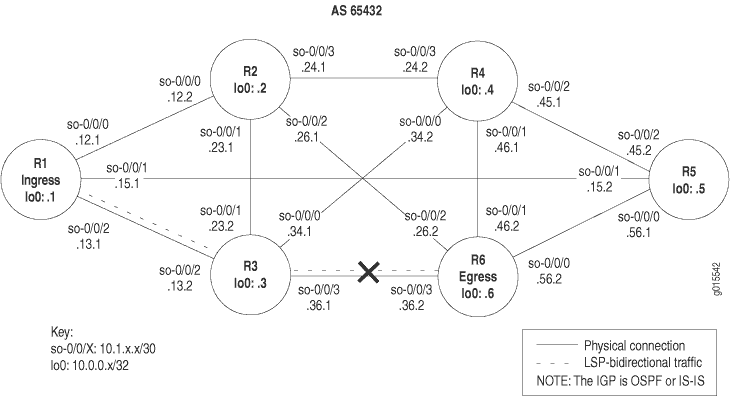
The network shown in Figure 4 is a fully meshed configuration where every directly connected interface can receive and send packets to every other similar interface. The LSP in this network is configured to run from ingress router R1, through transit router R3, to egress router R6. In addition, a reverse LSP is configured to run from R6 through R3 to R1, creating bidirectional traffic.
The cross shown in Figure 4 indicates where BGP is not being used to forward traffic through the LSP. Possible reasons for the LSP not working correctly are that the destination IP address of the LSP does not equal the BGP next hop or that BGP is not configured properly.
To check the BGP layer, follow these steps:
- Check That BGP Traffic Is Using the LSP
- Check BGP Sessions
- Verify the BGP Configuration
- Examine BGP Routes
- Verify Received BGP Routes
- Taking Appropriate Action for Resolving the Network Problem
- Check That BGP Traffic Is Using the LSP Again
Check That BGP Traffic Is Using the LSP
Purpose
At this level of the troubleshooting model, BGP and the LSP may be up, however BGP traffic might not be using the LSP to forward traffic.
Action
To verify that BGP traffic is using the LSP, enter the following Junos OS command-line interface (CLI) operational mode command from the ingress router:
user@host> traceroute hostname
Sample Output
command-name
user@R1> traceroute 100.100.6.1
traceroute to 100.100.6.1 (100.100.6.1), 30 hops max, 40 byte packets
 1  10.1.13.2 (10.1.13.2)  0.653 ms  0.590 ms  0.543 ms
 2  10.1.36.2 (10.1.36.2)  0.553 ms !N  0.552 ms !N  0.537 ms !N

user@R6> traceroute 100.100.1.1
traceroute to 100.100.1.1 (100.100.1.1), 30 hops max, 40 byte packets
 1  10.1.36.1 (10.1.36.1)  0.660 ms  0.551 ms  0.526 ms
 2  10.1.13.1 (10.1.13.1)  0.568 ms !N  0.553 ms !N  0.536 ms !N
Meaning
The sample output shows that BGP traffic is not using the LSP, consequently MPLS labels do not appear in the output. Instead of using the LSP, BGP traffic is using the interior gateway protocol (IGP) to reach the BGP next-hop LSP egress address for R6 and R1. The Junos OS default is to use LSPs for BGP traffic when the BGP next hop equals the LSP egress address.
Check BGP Sessions
Purpose
Display summary information about BGP and its neighbors to determine if routes are received from peers in the autonomous system (AS). When a BGP session is established, the peers are exchanging update messages.
Action
To check that BGP sessions are up, enter the following Junos OS CLI operational mode command from the ingress router:
user@host> show bgp summary
Sample Output 1
command-name
user@R1> show bgp summary
Groups: 1 Peers: 6  Down peers: 1
Table          Tot Paths  Act Paths Suppressed    History Damp State    Pending
inet.0                 1          1          0          0          0          0
Peer              AS      InPkt     OutPkt    OutQ   Flaps Last Up/Dwn State|#Active/Received/Damped...
10.0.0.2        65432      11257      11259       0       0 3d 21:49:57  0/0/0                0/0/0
10.0.0.3        65432      11257      11259       0       0 3d 21:49:57 0/0/0                0/0/0
10.0.0.4        65432      11257      11259       0       0 3d 21:49:57 0/0/0                0/0/0
10.0.0.5        65432      11257      11260       0       0 3d 21:49:57 0/0/0                0/0/0
10.0.0.6        65432          4       4572       0       1 3d 21:46:59 Active
10.1.36.2       65432      11252      11257       0       0 3d 21:46:49  1/1/0                0/0/0
Sample Output 2
command-name
user@R1> show bgp summary
Groups: 1 Peers: 5 Down peers: 0
Table          Tot Paths  Act Paths Suppressed    History Damp State    Pending
inet.0                 1          1          0          0          0          0
Peer              AS      InPkt     OutPkt    OutQ   Flaps Last Up/Dwn State|#Active/Received/Damped...
10.0.0.2        65432         64         68       0       0       32:18 0/0/0                0/0/0
10.0.0.3        65432         64         67       0       0       32:02 0/0/0                0/0/0
10.0.0.4        65432         64         67       0       0       32:10 0/0/0                0/0/0
10.0.0.5        65432         64         67       0       0       32:14 0/0/0                0/0/0
10.0.0.6        65432         38         39       0       1       18:02 1/1/0                0/0/0
Meaning
Sample Output 1 shows that one peer (egress router 10.0.0.6 ) is not established, as indicated by the Down Peers: 1 field. The last column (State|#Active/Received/Damped) shows that peer 10.0.0.6 is active, indicating that is it not established. All other peers are established as indicated by the number of active, received, and damped routes. For example, 0/0/0 for peer 10.0.0.2 indicates that no BGP routes were active or received in the routing table, and no BGP routes were damped; 1/1/0 for peer 10.1.36.2 indicates that one BGP route was active and received in the routing table, and no BGP routes were damped.
If the output of the show bgp summary command of an ingress router
shows that a neighbor is down, check the BGP configuration. For information
on checking the BGP configuration, see Verify the
BGP Configuration.
Sample Output 2 shows output from ingress router R1 after the BGP configurations on R1 and R6 were corrected in Taking Appropriate Action for Resolving the Network Problem.. All BGP peers are established and one route is active and received. No BGP routes were damped.
If the output of the show bgp summary command shows
that a neighbor is up but packets are not being forwarded, check for
received routes from the egress router. For information on checking
the egress router for received routes, see Verify Received
BGP Routes.
Verify the BGP Configuration
Purpose
For BGP to run on the router, you must define the local AS number, configure at least one group, and include information about at least one peer in the group (the peer's IP address and AS number). When BGP is part of an MPLS network, you must ensure that the LSP is configured with a destination IP address equal to the BGP next hop in order for BGP routes to be installed with the LSP as the next hop for those routes.
Action
To verify the BGP configuration, enter the following Junos OS CLI operational mode command:
user@host> show configuration
Sample Output 1
command-name
user@R1> show configuration
[...Output truncated...]
interfaces {
    so-0/0/0 {
        unit 0 {
            family inet {
                address 10.1.12.1/30;
            }
            family iso;
            family mpls;
        }
    }
    so-0/0/1 {
        unit 0 {
            family inet {
                address 10.1.15.1/30;
            }
            family iso;
            family mpls;
        }
    }
    so-0/0/2 {
        unit 0 {
            family inet {
                address 10.1.13.1/30;
            }
             family iso;
            family mpls;
        }
    }
    fxp0 {
        unit 0 {
            family inet {
                address 192.168.70.143/21;
            }
        }
    }
    lo0 {
        unit 0 {
            family inet {
                address 10.0.0.1/32;
            }
             family iso {
                address 49.0004.1000.0000.0001.00;
            }
        }
    }
}
routing-options {
    [...Output truncated...]
         route 100.100.1.0/24 reject;
    }
     router-id 10.0.0.1;
     autonomous-system 65432;
}
protocols {
    rsvp {
        interface so-0/0/0.0;
        interface so-0/0/1.0;
        interface so-0/0/2.0;
        interface fxp0.0 {
            disable;
        }
    }
    mpls {
        label-switched-path R1-to-R6 {
            to  10.0.0.6; <<< destination address of the LSP
        }
        inactive: interface so-0/0/0.0;
        inactive: interface so-0/0/1.0;
        interface so-0/0/2.0;
        interface fxp0.0 {
            disable;
        }
    }
    bgp {
        export send-statics; <<< missing local-address statement
         group internal {
            type internal;
            neighbor 10.0.0.2;
            neighbor 10.0.0.5;
            neighbor 10.0.0.4;
            neighbor 10.0.0.6;
            neighbor 10.0.0.3;
            neighbor 10.1.36.2; <<< incorrect interface address
        }
    }
    isis {
        level 1 disable;
        interface so-0/0/0.0;
        interface so-0/0/1.0;
        interface so-0/0/2.0;
        interface all {
            level 2 metric 10;
        }
        interface fxp0.0 {
            disable;
        }
        interface lo0.0 {
            passive;
        }
    }
    ospf {
        traffic-engineering;
        area 0.0.0.0 {
            interface so-0/0/0.0;
            interface so-0/0/1.0;
            interface so-0/0/2.0;
            interface lo0.0; {
                passive
            }
        }
    }
}
policy-options {
    policy-statement send-statics {
        term statics {
            from {
                route-filter 100.100.1.0/24 exact;
            }
            then accept;
        }
    }
}
Sample Output 2
command-name
user@R6> show configuration
[...Output truncated...]
interfaces {
    so-0/0/0 {
        unit 0 {
            family inet {
                address 10.1.56.2/30;
            }
            family iso;
            family mpls;
        }
    }
    so-0/0/1 {
        unit 0 {
            family inet {
                address 10.1.46.2/30;
            }
            family iso;
            family mpls;
        }
    }
    so-0/0/2 {
        unit 0 {
            family inet {
                address 10.1.26.2/30;
            }
            family iso;
            family mpls;
        }
    }
    so-0/0/3 {
        unit 0 {
            family inet {
                address 10.1.36.2/30;
            }
             family iso;
            family mpls;
        }
    }
    fxp0 {
        unit 0 {
            family inet {
                address 192.168.70.148/21;
            }
        }
    }
    lo0 {
        unit 0 {
            family inet {
                address 10.0.0.6/32;
                address 127.0.0.1/32;
            }
            family iso {
                address 49.0004.1000.0000.0006.00;
            }
        }
    }
}
routing-options {
    [...Output truncated...]
         route 100.100.6.0/24 reject;
    }
     router-id 10.0.0.6;
     autonomous-system 65432;
}
protocols {
    rsvp {
        interface so-0/0/0.0;
        interface so-0/0/1.0;
        interface so-0/0/2.0;
        interface so-0/0/3.0;
        interface fxp0.0 {
            disable;
        }
    }
    mpls {
        label-switched-path R6-to-R1 {
            to 10.0.0.1; <<< destination address of the reverse LSP
        }
        inactive: interface so-0/0/0.0;
        inactive: interface so-0/0/1.0;
        inactive: interface so-0/0/2.0;
        interface so-0/0/3.0;
    }
    bgp {
        group internal {
            type internal;
            export send-statics; <<< missing local-address statement
             neighbor 10.0.0.2;
            neighbor 10.0.0.3;
            neighbor 10.0.0.4;
            neighbor 10.0.0.5;
            neighbor 10.0.0.1;
            neighbor 10.1.13.1;         <<< incorrect interface address
        }
    }
    isis {
        level 1 disable;
        interface all {
            level 2 metric 10;
        }
        interface fxp0.0 {
            disable;
        }
        interface lo0.0 {
            passive;
        }
    }
    ospf {
        traffic-engineering;
        area 0.0.0.0 {
            interface so-0/0/0.0;
            interface so-0/0/1.0;
            interface so-0/0/2.0;
            interface so-0/0/3.0;
            interface lo0.0 {
                passive;
            }
        }
    }
}
policy-options {
    policy-statement send-statics {
        term statics {
            from {
                route-filter 100.100.6.0/24 exact;
            }
            then accept;
        }
    }
}
Meaning
The sample output shows the BGP configurations on ingress
router R1 and egress router R6. Both configurations
show the local AS (65432), one group (internal), and six peers configured. The underlying interior gateway protocol
is IS-IS, and the relevant interfaces are configured to run IS-IS.
In this configuration, the RID is manually configured
to avoid any duplicate RID problems, and all interfaces configured
with BGP include the family inet statement at the [edit interfaces type-fpc/pic/port unit logical-unit-number] hierarchy level.
Sample output for ingress router R1 and egress router R6 shows that the BGP protocol configuration is missing the local-address statement for the internal group. When the local-address statement is configured, BGP packets are forwarded
from the local router loopback (lo0) interface address,
which is the address to which BGP peers are peering. If the local-address statement is not configured, BGP packets are forwarded from the
outgoing interface address, which does not match the address to which
BGP peers are peering, and BGP does not come up.
On the ingress router, the IP address (10.0.0.1)
in the local-address statement should be the same as the
address configured for the LSP on the egress router (R6) in the to statement at the [edit protocols mpls
label-switched-path lsp-path-name] hierarchy level. BGP uses this address, which is identical to the
LSP address, to forward BGP traffic through the LSP.
In addition, the BGP configuration on R1 includes
two IP addresses for R6, an interface address (10.1.36.2) and a loopback (lo0) interface address (10.0.0.6), resulting in the LSP destination address (10.0.0.6)
not matching the BGP next-hop address (10.1.36.2). The
BGP configuration on R6 also includes two IP addresses
for R1, an interface address (10.1.13.1) and
a loopback (lo0) interface address, resulting in the reverse
LSP destination address (10.0.0.1) not matching the BGP
next-hop address (10.1.13.1).
In this instance, because the local-address statement
is missing in the BGP configurations of both routers and the LSP destination
address does not match the BGP next-hop address, BGP is not using
the LSP to forward traffic.
Examine BGP Routes
Purpose
You can examine the BGP path selection process to determine the single, active path when BGP receives multiple routes to the same destination. In this step, we examine the reverse LSP R6-to-R1, making R6 the ingress router for that LSP.
Action
To examine BGP routes and route selection, enter the following Junos OS CLI operational mode command:
user@host> show route destination-prefix detail
Sample Output 1
command-name
user@R6> show route 100.100.1.1 detail
inet.0: 30 destinations, 46 routes (29 active, 0 holddown, 1 hidden)
100.100.1.0/24 (1 entry, 1 announced)
        *BGP    Preference: 170/-101
                Source: 10.1.13.1
                Next hop: via so-0/0/3.0, selected
                 Protocol next hop: 10.1.13.1  Indirect next hop: 8671594 304
                State: <Active Int Ext>
                Local AS: 65432 Peer AS: 65432
                Age: 4d 5:15:39         Metric2: 2
                Task: BGP_65432.10.1.13.1+3048
                Announcement bits (2): 0-KRT 4-Resolve inet.0
                AS path: I
                Localpref: 100
                 Router ID: 10.0.0.1
Sample Output 2
command-name
user@R6> show route 100.100.1.1 detail
inet.0: 30 destinations, 46 routes (29 active, 0 holddown, 1 hidden)
100.100.1.0/24 (1 entry, 1 announced)
        *BGP    Preference: 170/-101
                Source: 10.0.0.1
                Next hop: via so-0/0/3.0 weight 1, selected
                 Label-switched-path R6-to-R1
                Label operation: Push 100000
                 Protocol next hop: 10.0.0.1  Indirect next hop: 8671330 301
                State: <Active Int Ext>
                Local AS: 65432 Peer AS: 65432
                Age: 24:35      Metric2: 2
                Task: BGP_65432.10.0.0.1+179
                Announcement bits (2): 0-KRT 4-Resolve inet.0
                AS path: I
                Localpref: 100
                 Router ID: 10.0.0.1
Meaning
Sample Output 1 shows that the BGP next hop (10.1.13.1) does not equal the LSP destination address (10.0.0.1)
in the to statement at the [edit protocols mpls label-switched-path label-switched-path-name] hierarchy level when the
BGP configuration of R6 and R1 is incorrect.
Sample Output 2, taken after the configurations on R1 and R6 are corrected, shows that the BGP next hop (10.0.0.1) and the LSP destination address (10.0.0.1) are the same, indicating that BGP can use the LSP to forward BGP traffic.
Verify Received BGP Routes
Purpose
Display the routing information received on router R6, the ingress router for the reverse LSP R6-to-R1.
Action
To verify that a particular BGP route is received on the egress router, enter the following Junos OS CLI operational mode command:
user@host> show route receive protocol bgp neighbor-address
Sample Output 1
command-name
user@R6> show route receive-protocol bgp 10.0.0.1
inet.0: 30 destinations, 46 routes (29 active, 0 holddown, 1 hidden)
<<< missing route
inet.3: 1 destinations, 1 routes (1 active, 0 holddown, 0 hidden)

iso.0: 1 destinations, 1 routes (1 active, 0 holddown, 0 hidden)

mpls.0: 3 destinations, 3 routes (3 active, 0 holddown, 0 hidden)

__juniper_private1__.inet6.0: 1 destinations, 1 routes (1 active, 0 holddown, 0 hidden)
Sample Output 2
command-name
user@R6> show route receive-protocol bgp 10.0.0.1
inet.0: 30 destinations, 46 routes (29 active, 0 holddown, 1 hidden)
  Prefix                  Nexthop              MED     Lclpref    AS path
* 100.100.1.0/24          10.0.0.1                     100        I

inet.3: 1 destinations, 1 routes (1 active, 0 holddown, 0 hidden)

iso.0: 1 destinations, 1 routes (1 active, 0 holddown, 0 hidden)

mpls.0: 3 destinations, 3 routes (3 active, 0 holddown, 0 hidden)

__juniper_private1__.inet6.0: 1 destinations, 1 routes (1 active, 0 holddown, 0 hidden)
Meaning
Sample Output 1 shows that ingress router R6 (reverse LSP R6-to-R1) does not receive any BGP routes into the inet.0 routing table when the BGP configurations of R1 and R6 are incorrect.
Sample Output 2 shows a BGP route installed in the inet.0 routing table after the BGP configurations on R1 and R6 are corrected using Taking Appropriate Action for Resolving the Network Problem.
Taking Appropriate Action for Resolving the Network Problem
Problem
Description
The appropriate action depends on the type
of problem you have isolated. In this example, a static route configured
on R2 is deleted from the [routing-options]
hierarchy level. Other appropriate actions might include the following:
Solution
Check the local router’s configuration and edit it if appropriate.
Troubleshoot the intermediate router.
Check the remote host configuration and edit it if appropriate.
Troubleshoot routing protocols.
Identify additional possible causes.
To resolve the problem in this example, enter the following Junos OS CLI commands:
[edit]
                          user@R2# delete routing-options static route destination-prefix
user@R2# commit and-quit
user@R2# show route destination-prefix
Sample Output
[edit]
user@R2# delete routing-options static route 10.0.0.5/32

[edit]
user@R2# commit and-quit
commit complete
Exiting configuration mode

user@R2> show route 10.0.0.5

inet.0: 22 destinations, 24 routes (22 active, 0 holddown, 0 hidden)
+ = Active Route, - = Last Active, * = Both

10.0.0.5/32        *[BGP/170] 3d 20:26:17, MED 5, localpref 100
                      AS path: 65001 I
                    > to 10.1.12.1 via so-0/0/0.0
Meaning
The sample output shows the static route deleted from the [routing-options] hierarchy and the new configuration committed.
The output for the show route command now shows the BGP
route as the preferred route, as indicated by the asterisk (*).
Check That BGP Traffic Is Using the LSP Again
Purpose
After taking the appropriate action to correct the error, the LSP needs to be checked again to confirm that BGP traffic is using the LSP and that the problem in the BGP layer has been resolved.
Action
To verify that BGP traffic is using the LSP, enter the following Junos OS CLI operational mode command from the ingress router:
user@host> traceroute hostname
Sample Output
command-name
user@R1> traceroute 100.100.6.1
traceroute to 100.100.6.1 (100.100.6.1), 30 hops max, 40 byte packets
 1  10.1.13.2 (10.1.13.2)  0.858 ms  0.740 ms  0.714 ms
      MPLS Label=100016 CoS=0 TTL=1 S=1
 2  10.1.36.2 (10.1.36.2)  0.592 ms !N  0.564 ms !N  0.548 ms !N

user@R6> traceroute 100.100.1.1
traceroute to 100.100.1.1 (100.100.1.1), 30 hops max, 40 byte packets
 1  10.1.36.1 (10.1.36.1)  0.817 ms  0.697 ms  0.771 ms
      MPLS Label=100000 CoS=0 TTL=1 S=1
 2  10.1.13.1 (10.1.13.1)  0.581 ms !N  0.567 ms !N  0.544 ms !N
Meaning
The sample output shows that MPLS labels are used to forward packets through the LSP. Included in the output is a label value (MPLS Label=100016), the time-to-live value (TTL=1), and the stack bit value (S=1).
The MPLS Label field is used to identify the packet to a particular LSP. It is a 20-bit field, with a maximum value of (2^^20-1), approximately 1,000,000.
The time-to-live (TTL) value contains a limit on the number of hops that this MPLS packet can travel through the network (1). It is decremented at each hop, and if the TTL value drops below one, the packet is discarded.
The bottom of the stack bit value (S=1) indicates that is the last label in the stack and that this MPLS packet has one label associated with it. The MPLS implementation in the Junos OS supports a stacking depth of 3 on the M-series routers and up to 5 on the T-series routing platforms. For more information on MPLS label stacking, see RFC 3032, MPLS Label Stack Encoding.
MPLS labels appear in the sample output because the traceroute command is issued to a BGP destination where the BGP next hop for
that route is the LSP egress address. The Junos OS by default uses
LSPs for BGP traffic when the BGP next hop equals the LSP egress address.
If the BGP next hop does not equal the LSP egress address, the
BGP traffic does not use the LSP, and consequently MPLS labels do
not appear in the output for the traceroute command, as
indicated in the sample output in Check BGP Sessions.
Display Sent or Received BGP Packets
Action
To configure the tracing for sent or received BGP protocol packets, follow these steps:
In configuration mode, go to the following hierarchy level:
[edit]
user@host# edit protocol bgp traceoptions
Configure the flag to display sent, received, or both sent and received packet information:
[edit protocols bgp traceoptions]
                 user@host#  set flag update send
or
[edit protocols bgp traceoptions]
user@host# set flag update receive
or
[edit protocols bgp traceoptions]
user@host# set flag update
Verify the configuration:
user@host# show
For example:
[edit protocols bgp traceoptions]
user@host# show
file bgplog size 10k files 10;
flag update send;
or
[edit protocols bgp traceoptions]
user@host# show
file bgplog size 10k files 10;
flag update receive;
or
[edit protocols bgp traceoptions]
user@host# show
file bgplog size 10k files 10;
flag update send receive;
Commit the configuration:
user@host# commit
View the contents of the file containing the detailed messages:
user@host# run show log filenameFor example:
[edit protocols bgp traceoptions]
user@host# run show log bgplog
Sep 13 12:58:23 trace_on: Tracing to "/var/log/bgplog" started
Sep 13 12:58:23 BGP RECV flags 0x40 code ASPath(2): <null>
Sep 13 12:58:23 BGP RECV flags 0x40 code LocalPref(5): 100
Sep 13 12:58:23 BGP RECV flags 0xc0 code Extended Communities(16): 2:10458:3
[...Output truncated...]
Examine Routes in the Forwarding Table
Purpose
When you run into problems, such as connectivity problems, you may need to examine routes in the forwarding table to verify that the routing protocol process has relayed the correct information into the forwarding table.
Action
To display the set of routes installed in the forwarding table, enter the following Junos OS CLI operational mode command:
user@host> show route forwarding-table
Sample Output
command-name
user@R2> show route forwarding-table
Routing table: inet
Internet:
Destination        Type RtRef Next hop           Type  Index NhRef Netif
default            perm     0                    rjct    10     1
10.0.0.2/32        intf     0 10.0.0.2           locl   256     1
10.0.0.3/32        user     1 10.1.23.0          ucst   282     4 so-0/0/1.0
10.0.0.4/32        user     1 10.1.24.0          ucst   290     7 so-0/0/3.0
10.0.0.6/32        user     1 10.1.24.0          ucst   290     7 so-0/0/3.0
10.1.12.0/30       intf     1 ff.3.0.21          ucst   278     6 so-0/0/0.0
10.1.12.0/32       dest     0 10.1.12.0          recv   280     1 so-0/0/0.0
10.1.12.2/32       intf     0 10.1.12.2          locl   277     1
10.1.12.3/32       dest     0 10.1.12.3          bcst   279     1 so-0/0/0.0
10.1.23.0/30       intf     0 ff.3.0.21          ucst   282     4 so-0/0/1.0
10.1.23.0/32       dest     0 10.1.23.0          recv   284     1 so-0/0/1.0
10.1.23.1/32       intf     0 10.1.23.1          locl   281     1
10.1.23.3/32       dest     0 10.1.23.3          bcst   283     1 so-0/0/1.0
10.1.24.0/30       intf     0 ff.3.0.21          ucst   290     7 so-0/0/3.0
10.1.24.0/32       dest     0 10.1.24.0          recv   292     1 so-0/0/3.0
10.1.24.1/32       intf     0 10.1.24.1          locl   289     1
10.1.24.3/32       dest     0 10.1.24.3          bcst   291     1 so-0/0/3.0
10.1.36.0/30       user     0 10.1.23.0          ucst   282     4 so-0/0/1.0
10.1.46.0/30       user     0 10.1.24.0          ucst   290     7 so-0/0/3.0
100.100.1.0/24     user     0 10.1.12.0          ucst   278     6 so-0/0/0.0
100.100.2.0/24     user     0 10.1.12.0          ucst   278     6 so-0/0/0.0
100.100.3.0/24     user     0 10.1.12.0          ucst   278     6 so-0/0/0.0
100.100.4.0/24     user     0 10.1.12.0          ucst   278     6 so-0/0/0.0
[...Output truncated...]
Meaning
The sample output shows the network-layer prefixes
and their next hops installed in the forwarding table. The output
includes the same next-hop information as in the show route detail command (the next-hop address and interface name). Additional information
includes the destination type, the next-hop type, the number of references
to this next hop, and an index into an internal next-hop database.
(The internal database contains additional information used by the
Packet Forwarding Engine to ensure proper encapsulation of packets
sent out an interface. This database is not accessible to the user.
For detailed information about the meanings of the various flags and types fields, see the Routing Policies, Firewall Filters, and Traffic Policers User Guide.
Example: Overriding the Default BGP Routing Policy on PTX Series Packet Transport Routers
This example shows how to override the default routing policy on packet transport routers, such as the PTX Series Packet Transport Routers.
Requirements
This example requires Junos OS Release 12.1 or later.
Overview
By default, the PTX Series routers do not install BGP routes in the forwarding table.
For PTX Series routers, the configuration of the from protocols bgp condition with the then accept action does not have the usual result that it has on other Junos OS routing devices. With the following routing policy on PTX Series routers, BGP routes do not get installed in the forwarding table.
user@host# show policy-options
policy-statement accept-no-install {
    term 1 {
        from protocol bgp;
        then accept;
    }
}
user@host# show routing-options
forwarding-table {
    export accept-no-install;
}
user@host> show route forwarding-table
Routing table: default.inet
Internet:
Destination        Type RtRef Next hop           Type Index NhRef Netif
default            perm     0                    rjct    36     2
No BGP routes are installed in the forwarding table. This is the expected behavior.
This example shows how to use the then install-to-fib action to effectively override the default BGP routing policy.
Configuration
CLI Quick Configuration
To quickly configure this example, copy the following commands, paste them into a text file, remove any line breaks, change any details necessary to match your network configuration, and then copy and paste the commands into the CLI at the [edit] hierarchy level.
set policy-options prefix-list install-bgp 66.0.0.1/32
set policy-options policy-statement override-ptx-series-default term 1 from prefix-list install-bgp
set policy-options policy-statement override-ptx-series-default term 1 then load-balance per-prefix
set policy-options policy-statement override-ptx-series-default term 1 then install-to-fib
set routing-options forwarding-table export override-ptx-series-default
Installing Selected BGP Routes in the Forwarding Table
Step-by-Step Procedure
The following example requires you to navigate various levels in the configuration hierarchy. For information about navigating the CLI, see Using the CLI Editor in Configuration Mode in the Junos OS CLI User Guide.
To install selected BGP routes in the forwarding table:
Configure a list of prefixes to install in the forwarding table.
[edit policy-options prefix-list install-bgp]
user@host# set 66.0.0.1/32
Configure the routing policy, applying the prefix list as a condition.
[edit policy-options policy-statement override-ptx-series-default term 1]
user@host# set from prefix-list install-bgp
user@host# set then install-to-fib
user@host# set then load-balance per-prefix
Apply the routing policy to the forwarding table.
[edit routing-options forwarding-table]
user@host# set export override-ptx-series-default
Results
From configuration mode, confirm your configuration by entering the show policy-options and show routing-options commands. If the output does not display the intended configuration, repeat the instructions in this example to correct the configuration.
user@host# show policy-options
prefix-list install-bgp {
    66.0.0.1/32;
}
policy-statement override-ptx-series-default {
    term 1 {
        from {
            prefix-list install-bgp;
        }
        then {
            load-balance per-prefix;
            install-to-fib;
        }
    }
}
user@host# show routing-options
forwarding-table {
    export override-ptx-series-default;
}
If you are done configuring the device, enter commit from configuration mode.
Verification
Confirm that the configuration is working properly.
Verifying That the Selected Route Is Installed in the Forwarding Table
Purpose
Make sure that the configured policy overrides the default policy.
Action
From operational mode, enter the show route forwarding-table command.
user@host> show route forwarding-table destination 66.0.0.1
Internet:
Destination        Type RtRef Next hop           Type Index NhRef Netif
66.0.0.1/32        user     0                    indr 2097159     3
                                                 ulst 2097156     2
                              5.1.0.2            ucst   574     1 et-6/0/0.1
                              5.2.0.2            ucst   575     1 et-6/0/0.2
Meaning
This output shows that the route to 66.0.0.1/32 is installed in the forwarding table.
Log BGP State Transition Events
Purpose
Border Gateway Protocol (BGP) state transitions indicate a network problem and need to be logged and investigated.
Action
To log BGP state transition events to the system log, follow these steps:
In configuration mode, go to the following hierarchy level:
[edit]
                 user@host# edit protocol bgp
Configure the system log:
user@host# set log-updown
Verify the configuration:
user@host# show
Commit the configuration:
user@host# commit
Meaning
Log messages from BGP state transition events are sufficient to diagnose most BGP session problems. Table 3 lists and describes the six states of a BGP session.
BGP State |
Description |
|---|---|
Idle |
This is the first state of a connection. BGP waits for a start event initiated by an administrator. The start event might be the establishment of a BGP session through router configuration or the resetting of an existing session. After the start event, BGP initializes its resources, resets a connect-retry timer, initiates a TCP transport connection, and starts listening for connections initiated by remote peers. BGP then transitions to a Connect state. If there are errors, BGP falls back to the Idle state. |
Connect |
BGP waits for the transport protocol connection to complete. If the TCP transport connection is successful, the state transitions to OpenSent. If the transport connection is not successful, the state transitions to Active. If the connect-retry timer has expired, the state remains in the Connect state, the timer is reset, and a transport connection is initiated. With any other event, the state goes back to Idle. |
Active |
BGP tries to acquire a peer by initiating a transport protocol connection. If it is successful, the state transitions to OpenSent. If the connect-retry timer expires, BGP restarts the connect timer and falls back to the Connect state. BGP continues to listen for a connection that may be initiated from another peer. The state may go back to Idle in case of other events, such as a stop event. In general, a neighbor state flip-flopping between Connect and Active is an indication that there is a problem with the TCP transport connection. Such a problem might be caused by many TCP retransmissions or the inability of a neighbor to reach the IP address of its peer. |
OpenSent |
BGP receives an open message from its peer. In the OpenSent state, BGP compares its autonomous system (AS) number with the AS number of its peer and recognizes whether the peer belongs to the same AS (internal BGP) or to a different AS (external BGP). The open message is checked for correctness. In case of errors, such as a bad version number of an unacceptable AS, BGP sends an error-notification message and goes back to Idle. For any other errors, such as expiration of the hold timer or a stop event, BGP sends a notification message with the corresponding error code and falls back to the Idle state. If there are no errors, BGP sends keepalive messages and resets the keepalive timer. In this state, the hold time is negotiated. If the hold time is 0, the hold and keepalive timers are not restarted. When a TCP transport disconnect is detected, the state falls back to Active. |
OpenConfirm |
BGP waits for a keepalive or notification message. If a keepalive is received, the state becomes Established, and the neighbor negotiation is complete. If the system receives an update or keepalive message, it restarts the hold timer (assuming that the negotiated hold time is not 0). If a notification message is received, the state falls back to Idle. The system sends periodic keepalive messages at the rate set by the keepalive timer. In case of a transport disconnect notification or in response to a stop event, the state falls back to Idle. In response to other events, the system sends a notification message with a finite state machine (FSM) error code and goes back to Idle. |
Established |
This is the final state in the neighbor negotiation. In this state, BGP exchanges update ackets with its peers and the hold timer is restarted at the receipt of an update or keepalive message when it is not set to zero. If the system receives a notification message, the state falls back to Idle. Update messages are checked for errors, such as missing attributes, duplicate attributes, and so on. If errors are found, a notification is sent to the peer, and the state falls back to Idle. BGP goes back to Idle when the hold timer expires, a disconnect notification is received from the transport protocol, a stop event is received, or in response to any other event. |
For more detailed BGP protocol packet information, configure BGP-specific tracing. See Checklist for Tracking Error Conditions for more information.
Configure BGP-Specific Options
Purpose
When unexpected events or problems occur, or if you want to diagnose BGP establishment issues, you can view more detailed information by configuring options specific to BGP. You can also configure tracing for a specific BGP peer or peer group. For more information, see the Junos System Basics Configuration Guide.
Display Detailed BGP Protocol Information
Action
To display BGP protocol information in detail, follow these steps:
In configuration mode, go to the following hierarchy level:
[edit]
user@host#  edit protocol bgp traceoptions
Configure the flag to display detailed BGP protocol messages:
[edit protocols bgp traceoptions]
user@host#  set flag update detail
Verify the configuration:
user@host# show
For example:
[edit protocols bgp traceoptions]
user@host# show
flag update detail;
Commit the configuration:
user@host# commit
View the contents of the file containing the detailed messages:
user@host# run show log filenameFor example:
[edit protocols bgp traceoptions]
user@pro5-a# run show log bgp
Sep 17 14:47:16 trace_on: Tracing to "/var/log/bgp" started
Sep 17 14:47:17 bgp_read_v4_update: receiving packet(s) from 10.255.245.53 (Internal AS 10458)
Sep 17 14:47:17 BGP RECV 10.255.245.53+179 -> 10.255.245.50+1141
Sep 17 14:47:17 BGP RECV message type 2 (Update) length 128
Sep 17 14:47:17 BGP RECV flags 0x40 code Origin(1): IGP
Sep 17 14:47:17 BGP RECV flags 0x40 code ASPath(2): 2
Sep 17 14:47:17 BGP RECV flags 0x80 code MultiExitDisc(4): 0
Sep 17 14:47:17 BGP RECV flags 0x40 code LocalPref(5): 100
Sep 17 14:47:17 BGP RECV flags 0xc0 code Extended Communities(16): 2:10458:1
[...Output truncated...]
Meaning
Table 4 lists tracing flags specific to BGP and presents example output for some of the flags. You can also configure tracing for a specific BGP peer or peer group. For more information, see the Junos System Basics Configuration Guide.
Tracing Flags |
Description |
Example Output |
|---|---|---|
aspath |
AS path regular expression operations |
Not available. |
damping |
Damping operations |
Nov 28 17:01:12 bgp_damp_change: Change event Nov 28 17:01:12 bgp_dampen: Damping 10.10.1.0 Nov 28 17:01:12 bgp_damp_change: Change event Nov 28 17:01:12 bgp_dampen: Damping 10.10.2.0 Nov 28 17:01:12 bgp_damp_change: Change event Nov 28 17:01:12 bgp_dampen: Damping 10.10.3.0 |
keepalive |
BGP keepalive messages |
Nov 28 17:09:27 bgp_send: sending 19 bytes to 10.217.5.101 (External AS 65471) Nov 28 17:09:27 Nov 28 17:09:27 BGP SEND 10.217.5.1+179 -> 10.217.5.101+52162 Nov 28 17:09:27 BGP SEND message type 4 (KeepAlive) length 19 Nov 28 17:09:28 Nov 28 17:09:28 BGP RECV 10.217.5.101+52162 -> 10.217.5.1+179 Nov 28 17:09:28 BGP RECV message type 4 (KeepAlive) length 19 |
open |
BGP open packets |
Nov 28 18:37:42 bgp_send: sending 37 bytes to 10.217.5.101 (External AS 65471) Nov 28 18:37:42 Nov 28 18:37:42 BGP SEND 10.217.5.1+179 -> 10.217.5.101+38135 Nov 28 18:37:42 BGP SEND message type 1 (Open) length 37 |
packets |
All BGP protocol packets |
Sep 27 17:45:31 BGP RECV 10.0.100.108+179 -> 10.0.100.105+1033 Sep 27 17:45:31 BGP RECV message type 4 (KeepAlive) length 19 Sep 27 17:45:31 bgp_send: sending 19 bytes to 10.0.100.108 (Internal AS 100) Sep 27 17:45:31 BGP SEND 10.0.100.105+1033 -> 10.0.100.108+179 Sep 27 17:45:31 BGP SEND message type 4 (KeepAlive) length 19 Sep 27 17:45:31 bgp_read_v4_update: receiving packet(s) from 10.0.100.108 (Internal AS 100) |
update |
Update packets |
Nov 28 19:05:24 BGP SEND 10.217.5.1+179 -> 10.217.5.101+55813 Nov 28 19:05:24 BGP SEND message type 2 (Update) length 53 Nov 28 19:05:24 bgp_send: sending 65 bytes to 10.217.5.101 (External AS 65471) Nov 28 19:05:24 Nov 28 19:05:24 BGP SEND 10.217.5.1+179 -> 10.217.5.101+55813 Nov 28 19:05:24 BGP SEND message type 2 (Update) length 65 Nov 28 19:05:24 bgp_send: sending 55 bytes to 10.217.5.101 (External AS 65471) |
Diagnose BGP Session Establishment Problems
Purpose
To trace BGP session establishment problems.
Action
To trace BGP session establishment problems, follow these steps:
In configuration mode, go to the following hierarchy level:
[edit]
                 user@host#  edit protocol bgp
Configure BGP open messages:
[edit protocols bgp]
user@host#  set traceoptions flag open detail
Verify the configuration:
user@host# show
For example:
[edit protocols bgp]
user@host# show
traceoptions {
        file bgplog size 10k files 10;
        flag open detail;
}
Commit the configuration:
user@host# commit
View the contents of the file containing the detailed messages:
user@host#run show log filenameFor example:
[edit protocols bgp]
user@hotst# run show log bgplog
Sep 17 17:13:14 trace_on: Tracing to "/var/log/bgplog" started
Sep 17 17:13:14 bgp_read_v4_update: done with 201.0.0.2 (Internal AS 10458) received 19 octets 0 updates 0 routes
Sep 17 17:13:15 bgp_read_v4_update: receiving packet(s) from 201.0.0.3 (Internal AS 10458)
Sep 17 17:13:15 bgp_read_v4_update: done with 201.0.0.3 (Internal AS 10458) received 19 octets 0 updates 0 routes
Sep 17 17:13:44 bgp_read_v4_update: receiving packet(s) from 201.0.0.2 (Internal AS 10458)
[...Output truncated...]
Configure IS-IS-Specific Options
Purpose
When unexpected events or problems occur, or if you want to diagnose IS-IS adjacency establishment issues, you can view more detailed information by configuring options specific to IS-IS.
To configure IS-IS options, follow these steps:
- Displaying Detailed IS-IS Protocol Information
- Displaying Sent or Received IS-IS Protocol Packets
- Analyzing IS-IS Link-State PDUs in Detail
Displaying Detailed IS-IS Protocol Information
Action
To trace IS-IS messages in detail, follow these steps:
Configure the flag to display detailed IS-IS protocol messages.
[edit protocols isis traceoptions]
user@host#  set flag hello detail
Verify the configuration.
user@host# show
For example:
[edit protocols isis traceoptions]
user@host# show
file isislog size 10k files 10;
flag hello detail;
Commit the configuration.
user@host# commit
View the contents of the file containing the detailed messages.
user@host# run show log filenameFor example:
user@host# run show log isislog
Nov 29 23:17:50 trace_on: Tracing to "/var/log/isislog" started
Nov 29 23:17:50 Sending PTP IIH on so-1/1/1.0
Nov 29 23:17:53 Sending PTP IIH on so-1/1/0.0
Nov 29 23:17:54 Received PTP IIH, source id abc-core-01 on so-1/1/0.0
Nov 29 23:17:54     from interface index 11
Nov 29 23:17:54     max area 0, circuit type l2, packet length 4469
Nov 29 23:17:54     hold time 30, circuit id 6
Nov 29 23:17:54     neighbor state up
Nov 29 23:17:54     speaks IP
Nov 29 23:17:54     area address 99.0008 (1)
Nov 29 23:17:54     IP address 10.10.10.29
Nov 29 23:17:54     4396 bytes of total padding
Nov 29 23:17:54     updating neighbor abc-core-01
Nov 29 23:17:55 Received PTP IIH, source id abc-core-02 on so-1/1/1.0
Nov 29 23:17:55     from interface index 12
Nov 29 23:17:55     max area 0, circuit type l2, packet length 4469
Nov 29 23:17:55     hold time 30, circuit id 6
Nov 29 23:17:55     neighbor state up
Nov 29 23:17:55     speaks IP
Nov 29 23:17:55     area address 99.0000 (1)
Nov 29 23:17:55     IP address 10.10.10.33
Nov 29 23:17:55     4396 bytes of total padding
Nov 29 23:17:55     updating neighbor abc-core-02
Meaning
Table 5 lists tracing flags that can be configured specific to IS-IS and presents example output for some of the flags.
Tracing Flags |
Description |
Example Output |
|---|---|---|
csn |
Complete sequence number PDU (CSNP) |
Nov 28 20:02:48 Sending L2 CSN on interface so-1/1/0.0Nov 28 20:02:48 Sending L2 CSN on interface so-1/1/1.0 With the detail option. Nov 28 20:06:08 Sending L2 CSN on interface so-1/1/1.0Nov 28 20:06:08 LSP abc-core-01.00-00 lifetime 1146Nov 28 20:06:08 sequence 0x1c4f8 checksum 0xa1e9Nov 28 20:06:08 LSP abc-core-02.00-00 lifetime 411Nov 28 20:06:08 sequence 0x7435 checksum 0x5424Nov 28 20:06:08 LSP abc-brdr-01.00-00 lifetime 465Nov 28 20:06:08 sequence 0xf73 checksum 0xab10Nov 28 20:06:08 LSP abc-edge-01.00-00 lifetime 1089Nov 28 20:06:08 sequence 0x1616 checksum 0xdb29Nov 28 20:06:08 LSP abc-edge-02.00-00 lifetime 1103Nov 28 20:06:08 sequence 0x45cc checksum 0x6883 |
hello |
Hello packet |
Nov 28 20:13:50 Sending PTP IIH on so-1/1/1.0Nov 28 20:13:50 Received PTP IIH, source id abc-core-01 on so-1/1/0.0Nov 28 20:13:53 Received PTP IIH, source id abc-core-02 on so-1/1/1.0Nov 28 20:13:57 Sending PTP IIH on so-1/1/0.0Nov 28 20:13:58 Received PTP IIH, source id abc-core-01 on so-1/1/0.0Nov 28 20:13:59 Sending PTP IIH on so-1/1/1.0 |
lsp |
Link-state PDUs (LSPs) |
Nov 28 20:15:46 Received L2 LSP abc-edge-01.00-00, interface so-1/1/0.0Nov 28 20:15:46 from abc-core-01Nov 28 20:15:46 sequence 0x1617, checksum 0xd92a, lifetime 1197Nov 28 20:15:46 Updating L2 LSP abc-edge-01.00-00 in TEDNov 28 20:15:47 Received L2 LSP abc-edge-01.00-00, interface so-1/1/1.0Nov 28 20:15:47 from abc-core-02Nov 28 20:15:47 sequence 0x1617, checksum 0xd92a, lifetime 1197 |
lsp-generation |
Link-state PDU generation packets |
Nov 28 20:21:24 Regenerating L1 LSP abc-edge-03.00-00, old sequence 0x682Nov 28 20:21:27 Rebuilding L1, fragment abc-edge-03.00-00Nov 28 20:21:27 Rebuilt L1 fragment abc-edge-03.00-00, size 59Nov 28 20:31:52 Regenerating L2 LSP abc-edge-03.00-00, old sequence 0x689Nov 28 20:31:54 Rebuilding L2, fragment abc-edge-03.00-00Nov 28 20:31:54 Rebuilt L2 fragment abc-edge-03.00-00, size 256Nov 28 20:34:05 Regenerating L1 LSP abc-edge-03.00-00, old sequence 0x683Nov 28 20:34:08 Rebuilding L1, fragment abc-edge-03.00-00Nov 28 20:34:08 Rebuilt L1 fragment abc-edge-03.00-00, size 59 |
packets |
All IS-IS protocol packets |
Not available. |
psn |
Partial sequence number PDU (PSNP) packets |
Nov 28 20:40:39 Received L2 PSN, source abc-core-01, interface so-1/1/0.0Nov 28 20:40:39 Received L2 PSN, source abc-core-02, interface so-1/1/1.0Nov 28 20:41:36 Sending L2 PSN on interface so-1/1/1.0Nov 28 20:41:36 Sending L2 PSN on interface so-1/1/0.0Nov 28 20:42:35 Received L2 PSN, source abc-core-02, interface so-1/1/1.0Nov 28 20:42:35 LSP abc-edge-03.00-00 lifetime 1196Nov 28 20:42:35 sequence 0x68c checksum 0x746dNov 28 20:42:35 Received L2 PSN, source abc-core-01, interface so-1/1/0.0Nov 28 20:42:35 LSP abc-edge-03.00-00 lifetime 1196Nov 28 20:42:35 sequence 0x68c checksum 0x746dNov 28 20:42:49 Sending L2 PSN on interface so-1/1/1.0Nov 28 20:42:49 LSP abc-core-01.00-00 lifetime 1197Nov 28 20:42:49 sequence 0x1c4fb checksum 0x9becNov 28 20:42:49 Sending L2 PSN on interface so-1/1/0.0Nov 28 20:42:49 LSP abc-core-01.00-00 lifetime 1197Nov 28 20:42:49 sequence 0x1c4fb checksum 0x9bec |
spf |
Shortest-path-first (SPF) calculations |
Nov 28 20:44:01 Scheduling SPF for L1: ReconfigNov 28 20:44:01 Scheduling multicast SPF for L1: ReconfigNov 28 20:44:01 Scheduling SPF for L2: ReconfigNov 28 20:44:01 Scheduling multicast SPF for L2: ReconfigNov 28 20:44:02 Running L1 SPFNov 28 20:44:02 L1 SPF initialization complete: 0.000099s cumulative timeNov 28 20:44:02 L1 SPF primary processing complete: 0.000303s cumulative timeNov 28 20:44:02 L1 SPF result postprocessing complete: 0.000497s cumulative timeNov 28 20:44:02 L1 SPF RIB postprocessing complete: 0.000626s cumulative timeNov 28 20:44:02 L1 SPF routing table postprocessing complete: 0.000736s cumulative time |
See Also
Displaying Sent or Received IS-IS Protocol Packets
To configure the tracing for only sent or received IS-IS protocol packets, follow these steps:
Configure the flag to display sent, received, or both sent and received packets.
[edit protocols isis traceoptions]
user@host# set flag hello send
or
[edit protocols isis traceoptions]
user@host# set flag hello receive
or
[edit protocols isis traceoptions]
user@host# set flag hello
Verify the configuration.
user@host# show
For example:
[edit protocols isis traceoptions]
user@host# show
file isislog size 10k files 10;
flag hello send;
or
[edit protocols isis traceoptions]
user@host# show
file isislog size 10k files 10;
flag hello receive;
or
[edit protocols isis traceoptions]
user@host# show
file isislog size 10k files 10;
flag hello send receive;
Commit the configuration.
user@host# commit
View the contents of the file containing the detailed messages.
user@host# run show log filenameFor example:
user@host# run show log isislog
Sep 27 18:17:01 ISIS periodic xmit to 01:80:c2:00:00:15 (IFL 2)
Sep 27 18:17:01 ISIS periodic xmit to 01:80:c2:00:00:14 (IFL 2)
Sep 27 18:17:03 ISIS periodic xmit to 01:80:c2:00:00:15 (IFL 2)
Sep 27 18:17:04 ISIS periodic xmit to 01:80:c2:00:00:14 (IFL 2)
Sep 27 18:17:06 ISIS L2 hello from 0000.0000.0008 (IFL 2) absorbed
Sep 27 18:17:06 ISIS periodic xmit to 01:80:c2:00:00:15 (IFL 2)
Sep 27 18:17:06 ISIS L1 hello from 0000.0000.0008 (IFL 2) absorbed
See Also
Analyzing IS-IS Link-State PDUs in Detail
To analyze IS-IS link-state PDUs in detail, follow these steps:
Configure IS-IS open messages.
[edit protocols isis traceoptions]
user@host# set flag lsp detail
Verify the configuration.
user@host# show
For example:
[edit protocols isis traceoptions]
user@host# show
file isislog size 5m world-readable;
flag error;
flag lsp detail;
Commit the configuration.
user@host# commit
View the contents of the file containing the detailed messages.
user@host# run show log filenameFor example:
user@host# run show log isislog
Nov 28 20:17:24 Received L2 LSP abc-core-01.00-00, interface so-1/1/0.0
Nov 28 20:17:24     from abc-core-01
Nov 28 20:17:24     sequence 0x1c4f9, checksum 0x9fea, lifetime 1199
Nov 28 20:17:24     max area 0, length 426
Nov 28 20:17:24     no partition repair, no database overload
Nov 28 20:17:24     IS type 3, metric type 0
Nov 28 20:17:24     area address 99.0908 (1)
Nov 28 20:17:24     speaks CLNP
Nov 28 20:17:24     speaks IP
Nov 28 20:17:24     dyn hostname abc-core-01
Nov 28 20:17:24     IP address 10.10.134.11
Nov 28 20:17:24    IP prefix: 10.10.10.0/30 metric 1 up
Nov 28 20:17:24    IP prefix: 10.10.10.4/30 metric 5 up
Nov 28 20:17:24    IP prefix: 10.10.10.56/30 metric 5 up
Nov 28 20:17:24    IP prefix: 10.10.10.52/30 metric 1 up
Nov 28 20:17:24    IP prefix: 10.10.10.64/30 metric 5 up
Nov 28 20:17:24    IP prefix: 10.10.10.20/30 metric 5 up
Nov 28 20:17:24    IP prefix: 10.10.10.28/30 metric 5 up
Nov 28 20:17:24    IP prefix: 10.10.10.44/30 metric 5 up
Nov 28 20:17:24     IP prefix 10.10.10.0 255.255.255.252
Nov 28 20:17:24     internal, metrics: default 1
Nov 28 20:17:24     IP prefix 10.10.10.4 255.255.255.252
Nov 28 20:17:24     internal, metrics: default 5
Nov 28 20:17:24     IP prefix 10.10.10.56 255.255.255.252
Nov 28 20:17:24     internal, metrics: default 5
Nov 28 20:17:24     IP prefix 10.10.10.52 255.255.255.252
Nov 28 20:17:24     internal, metrics: default 1
Nov 28 20:17:24     IP prefix 10.10.10.64 255.255.255.252
Nov 28 20:17:24     internal, metrics: default 5
Nov 28 20:17:24     IP prefix 10.10.10.20 255.255.255.252
Nov 28 20:17:24     internal, metrics: default 5
Nov 28 20:17:24     IP prefix 10.10.10.28 255.255.255.252
Nov 28 20:17:24     internal, metrics: default 5
Nov 28 20:17:24     IP prefix 10.10.10.44 255.255.255.252
Nov 28 20:17:24     internal, metrics: default 5
Nov 28 20:17:24     IS neighbors:
Nov 28 20:17:24     IS neighbor abc-core-02.00
Nov 28 20:17:24     internal, metrics: default 1
[...Output truncated...]
Nov 28 20:17:24     internal, metrics: default 5
Nov 28 20:17:24     IS neighbor abc-brdr-01.00
Nov 28 20:17:24     internal, metrics: default 5
Nov 28 20:17:24     IS neighbor abc-core-02.00, metric: 1
Nov 28 20:17:24     IS neighbor abc-esr-02.00, metric: 5
Nov 28 20:17:24     IS neighbor abc-edge-03.00, metric: 5
Nov 28 20:17:24     IS neighbor abc-edge-01.00, metric: 5
Nov 28 20:17:24     IS neighbor abc-edge-02.00, metric: 5
Nov 28 20:17:24     IS neighbor abc-brdr-01.00, metric: 5
Nov 28 20:17:24    IP prefix: 10.10.134.11/32 metric 0 up
Nov 28 20:17:24    IP prefix: 10.11.0.0/16 metric 5 up
Nov 28 20:17:24    IP prefix: 10.211.0.0/16 metric 0 up
Nov 28 20:17:24     IP prefix 10.10.134.11 255.255.255.255
Nov 28 20:17:24     internal, metrics: default 0
Nov 28 20:17:24     IP prefix 10.11.0.0 255.255.0.0
Nov 28 20:17:24     internal, metrics: default 5
Nov 28 20:17:24     IP prefix 10.211.0.0 255.255.0.0
Nov 28 20:17:24     internal, metrics: default 0
Nov 28 20:17:24     Updating LSP
Nov 28 20:17:24 Updating L2 LSP abc-core-01.00-00 in TED
Nov 28 20:17:24 Analyzing subtlv's for abc-core-02.00
Nov 28 20:17:24 Analysis complete
Nov 28 20:17:24 Analyzing subtlv's for abc-esr-02.00
Nov 28 20:17:24 Analysis complete
Nov 28 20:17:24 Analyzing subtlv's for abc-edge-03.00
Nov 28 20:17:24 Analysis complete
Nov 28 20:17:24 Analyzing subtlv's for abc-edge-01.00
Nov 28 20:17:24 Analysis complete
Nov 28 20:17:24 Analyzing subtlv's for abc-edge-02.00
Nov 28 20:17:24 Analysis complete
Nov 28 20:17:24 Analyzing subtlv's for abc-brdr-01.00
Nov 28 20:17:24 Analysis complete
Nov 28 20:17:24     Scheduling L2 LSP abc-core-01.00-00 sequence 0x1c4f9 on interface so-1/1/1.0
See Also
Configure OSPF-Specific Options
Purpose
When unexpected events or problems occur, or if you want to diagnose OSPF neighbor establishment issues, you can view more detailed information by configuring options specific to OSPF.
To configure OSPF options, follow these steps:
- Diagnose OSPF Session Establishment Problems
- Analyze OSPF Link-State Advertisement Packets in Detail
Diagnose OSPF Session Establishment Problems
Action
To trace OSPF messages in detail, follow these steps:
In configuration mode, go to the following hierarchy level:
[edit]
user@host# edit protocols ospf traceoptions
Configure OSPF hello messages:
[edit protocols ospf traceoptions]
user@host# set flag hello detail
Verify the configuration:
user@host# show
For example:
[edit protocols ospf traceoptions]
user@host# show
file ospf size 5m world-readable;
flag hello detail;
Commit the configuration:
user@host# commit
View the contents of the file containing the detailed messages:
user@host# run show log filenameFor example:
user@host# run show log ospf
Dec  2 16:14:24   Version 2, length 44, ID 10.0.0.6, area 1.0.0.0
Dec  2 16:14:24   checksum 0xf01a, authtype 0
Dec  2 16:14:24   mask 0.0.0.0, hello_ivl 10, opts 0x2, prio 128
Dec  2 16:14:24   dead_ivl 40, DR 0.0.0.0, BDR 0.0.0.0
Dec  2 16:14:24 OSPF sent Hello (1) -> 224.0.0.5 (so-1/1/2.0)
Dec  2 16:14:24   Version 2, length 44, ID 10.0.0.6, area 1.0.0.0
Dec  2 16:14:24   checksum 0xf01a, authtype 0
Dec  2 16:14:24   mask 0.0.0.0, hello_ivl 10, opts 0x2, prio 128
Dec  2 16:14:24   dead_ivl 40, DR 0.0.0.0, BDR 0.0.0.0
Dec  2 16:14:26 OSPF rcvd Hello 10.10.10.33 -> 224.0.0.5 (so-1/1/1.0)
Dec  2 16:14:26   Version 2, length 48, ID 10.10.134.12, area 0.0.0.0
Dec  2 16:14:26   checksum 0x99b8, authtype 0Dec  2 16:14:26   mask 255.255.255.252, hello_ivl 10, opts 0x2, prio 1
ec  2 16:14:26   dead_ivl 40, DR 0.0.0.0, BDR 0.0.0.0
Dec  2 16:14:29 OSPF rcvd Hello 10.10.10.29 -> 224.0.0.5 (so-1/1/0.0)
Dec  2 16:14:29   Version 2, length 48, ID 10.108.134.11, area 0.0.0.0
Dec  2 16:14:29   checksum 0x99b9, authtype 0Dec  2 16:14:29   mask 255.255.255.252, hello_ivl 10, opts 0x2, prio 1
Dec  2 16:14:29   dead_ivl 40, DR 0.0.0.0, BDR 0.0.0.0
Meaning
Table 6 lists OSPF tracing flags and presents example output for some of the flags.
Tracing Flags |
Description |
Example Output |
|---|---|---|
database-descripttion |
All database description packets |
Dec 2 15:44:51 RPD_OSPF_NBRDOWN: OSPF neighbor 10.10.10.29 (so-1/1/0.0) state changed from Full to Down Dec 2 15:44:51 RPD_OSPF_NBRDOWN: OSPF neighbor 10.10.10.33 (so-1/1/1.0) state changed from Full to Down Dec 2 15:44:55 RPD_OSPF_NBRUP: OSPF neighbor 10.10.10.33 (so-1/1/1.0) state changed from Init to ExStart Dec 2 15:44:55 OSPF sent DbD (2) -> 224.0.0.5 (so-1/1/1.0) Dec 2 15:44:55 Version 2, length 32, ID 10.0.0.6, area 0.0.0.0 Dec 2 15:44:55 checksum 0xf76b, authtype 0 Dec 2 15:44:55 options 0x42, i 1, m 1, ms 1, seq 0xa009eee, mtu 4470 Dec 2 15:44:55 OSPF rcvd DbD 10.10.10.33 -> 224.0.0.5 (so-1/1/1.0) Dec 2 15:44:55 Version 2, length 32, ID 10.10.134.12, area 0.0.0.0 Dec 2 15:44:55 checksum 0x312c, authtype 0 Dec 2 15:44:55 options 0x42, i 1, m 1, ms 1, seq 0x2154, mtu 4470 |
error |
OSPF errored packets |
Dec 2 15:49:34 OSPF packet ignored: no matching interface from 172.16.120.29 Dec 2 15:49:44 OSPF packet ignored: no matching interface from 172.16.120.29 Dec 2 15:49:54 OSPF packet ignored: no matching interface from 172.16.120.29 Dec 2 15:50:04 OSPF packet ignored: no matching interface from 172.16.120.29 Dec 2 15:50:14 OSPF packet ignored: no matching interface from 172.16.120.29 |
event |
OSPF state transitions |
Dec 2 15:52:35 OSPF interface ge-2/2/0.0 state changed from DR to DR Dec 2 15:52:35 OSPF interface ge-3/1/0.0 state changed from DR to DR Dec 2 15:52:35 OSPF interface ge-3/2/0.0 state changed from DR to DR Dec 2 15:52:35 OSPF interface ge-4/2/0.0 state changed from DR to DR Dec 2 15:53:21 OSPF neighbor 10.10.10.29 (so-1/1/0.0) state changed from Full to Down Dec 2 15:53:21 RPD_OSPF_NBRDOWN: OSPF neighbor 10.10.10.29 (so-1/1/0.0) state changed from Full to Down Dec 2 15:53:21 OSPF neighbor 10.10.10.33 (so-1/1/1.0) state changed from Full to Down Dec 2 15:53:21 RPD_OSPF_NBRDOWN: OSPF neighbor 10.10.10.33 (so-1/1/1.0) state changed from Full to Down Dec 2 15:53:25 OSPF neighbor 10.10.10.33 (so-1/1/1.0) state changed from Down to Init Dec 2 15:53:25 OSPF neighbor 10.10.10.33 (so-1/1/1.0) state changed from Init to ExStart Dec 2 15:53:25 RPD_OSPF_NBRUP: OSPF neighbor 10.10.10.33 (so-1/1/1.0) state changed from Init to ExStart Dec 2 15:53:25 OSPF neighbor 10.10.10.33 (so-1/1/1.0) state changed from ExStart to Exchange Dec 2 15:53:25 OSPF neighbor 10.10.10.33 (so-1/1/1.0) state changed from Exchange to Full Dec 2 15:53:25 RPD_OSPF_NBRUP: OSPF neighbor 10.10.10.33 (so-1/1/1.0) state changed from Exchange to Full |
flooding |
Link-state flooding packets |
Dec 2 15:55:21 OSPF LSA Summary 10.218.0.0 10.0.0.6 flooding on so-1/1/0.0 Dec 2 15:55:21 OSPF LSA Summary 10.218.0.0 10.0.0.6 flooding on so-1/1/1.0 Dec 2 15:55:21 OSPF LSA Summary 10.218.0.0 10.0.0.6 on no so-1/1/2.0 rexmit lists, no flood Dec 2 15:55:21 OSPF LSA Summary 10.218.0.0 10.0.0.6 on no so-1/1/3.0 rexmit lists, no flood Dec 2 15:55:21 OSPF LSA Summary 10.245.0.1 10.0.0.6 on no so-1/1/2.0 rexmit lists, no flood Dec 2 15:55:21 OSPF LSA Summary 10.245.0.1 10.0.0.6 on no so-1/1/3.0 rexmit lists, no flood |
hello |
Hello packets |
Dec 2 15:57:25 OSPF sent Hello (1) -> 224.0.0.5 (ge-3/1/0.0) Dec 2 15:57:25 Version 2, length 44, ID 10.0.0.6, area 2.0.0.0 Dec 2 15:57:25 checksum 0xe43f, authtype 0 Dec 2 15:57:25 mask 255.255.0.0, hello_ivl 10, opts 0x2, prio 128 Dec 2 15:57:25 dead_ivl 40, DR 10.218.0.1, BDR 0.0.0.0 Dec 2 15:57:25 OSPF rcvd Hello 10.10.10.33 -> 224.0.0.5 (so-1/1/1.0) Dec 2 15:57:25 Version 2, length 48, ID 10.10.134.12, area 0.0.0.0 Dec 2 15:57:25 checksum 0x99b8, authtype 0 Dec 2 15:57:25 mask 255.255.255.252, hello_ivl 10, opts 0x2, prio 1 Dec 2 15:57:25 dead_ivl 40, DR 0.0.0.0, BDR 0.0.0.0 Dec 2 15:57:27 OSPF sent Hello (1) -> 224.0.0.5 (ge-3/2/0.0) Dec 2 15:57:27 Version 2, length 44, ID 10.0.0.6, area 2.0.0.0 Dec 2 15:57:27 checksum 0xe4a5, authtype 0 Dec 2 15:57:27 mask 255.255.0.0, hello_ivl 10, opts 0x2, prio 128 Dec 2 15:57:27 dead_ivl 40, DR 10.116.0.1, BDR 0.0.0.0 Dec 2 15:57:28 OSPF rcvd Hello 10.10.10.29 -> 224.0.0.5 (so-1/1/0.0) Dec 2 15:57:28 Version 2, length 48, ID 10.10.134.11, area 0.0.0.0 Dec 2 15:57:28 checksum 0x99b9, authtype 0 Dec 2 15:57:28 mask 255.255.255.252, hello_ivl 10, opts 0x2, prio 1 Dec 2 15:57:28 dead_ivl 40, DR 0.0.0.0, BDR 0.0.0.0 |
lsa-ack |
Link-state acknowledgment packets |
Dec 2 16:00:11 OSPF rcvd LSAck 10.10.10.29 -> 224.0.0.5 (so-1/1/0.0) Dec 2 16:00:11 Version 2, length 44, ID 10.10.134.11, area 0.0.0.0 Dec 2 16:00:11 checksum 0xcdbf, authtype 0 Dec 2 16:00:11 OSPF rcvd LSAck 10.10.10.33 -> 224.0.0.5 (so-1/1/1.0) Dec 2 16:00:11 Version 2, length 144, ID 10.10.134.12, area 0.0.0.0 Dec 2 16:00:11 checksum 0x73bc, authtype 0 Dec 2 16:00:16 OSPF rcvd LSAck 10.10.10.33 -> 224.0.0.5 (so-1/1/1.0) Dec 2 16:00:16 Version 2, length 44, ID 10.10.134.12, area 0.0.0.0 Dec 2 16:00:16 checksum 0x8180, authtype 0 |
lsa-request |
Link-state request packets |
Dec 2 16:01:38 OSPF rcvd LSReq 10.10.10.29 -> 224.0.0.5 (so-1/1/0.0) Dec 2 16:01:38 Version 2, length 108, ID 10.10.134.11, area 0.0.0.0 Dec 2 16:01:38 checksum 0xe86, authtype 0 |
lsa-update |
Link-state update packets |
Dec 2 16:09:12 OSPF built router LSA, area 0.0.0.0 Dec 2 16:09:12 OSPF built router LSA, area 1.0.0.0 Dec 2 16:09:12 OSPF built router LSA, area 2.0.0.0 Dec 2 16:09:13 OSPF sent LSUpdate (4) -> 224.0.0.5 (so-1/1/0.0) Dec 2 16:09:13 Version 2, length 268, ID 10.0.0.6, area 0.0.0.0 Dec 2 16:09:13 checksum 0x8047, authtype 0 Dec 2 16:09:13 adv count 7 Dec 2 16:09:13 OSPF sent LSUpdate (4) -> 224.0.0.5 (so-1/1/1.0) Dec 2 16:09:13 Version 2, length 268, ID 10.0.0.6, area 0.0.0.0 Dec 2 16:09:13 checksum 0x8047, authtype 0 Dec 2 16:09:13 adv count 7 |
packets |
All OSPF packets |
Not available. |
packet-dump |
Dump the contents of selected packet types |
Not available. |
spf |
SPF calculations |
Dec 2 16:08:03 OSPF full SPF refresh scheduled Dec 2 16:08:04 OSPF SPF start, area 1.0.0.0 Dec 2 16:08:04 OSPF add LSA Router 10.0.0.6 distance 0 to SPF list Dec 2 16:08:04 SPF elapsed time 0.000525s Dec 2 16:08:04 Stub elapsed time 0.000263s Dec 2 16:08:04 OSPF SPF start, area 2.0.0.0 Dec 2 16:08:04 OSPF add LSA Router 10.0.0.6 distance 0 to SPF list Dec 2 16:08:04 SPF elapsed time 0.000253s Dec 2 16:08:04 Stub elapsed time 0.000249s Dec 2 16:08:04 OSPF SPF start, area 0.0.0.0 Dec 2 16:08:04 OSPF add LSA Router 10.0.0.6 distance 0 to SPF list Dec 2 16:08:04 OSPF add LSA Router 10.10.134.11 distance 1 to SPF list Dec 2 16:08:04 IP nexthop so-1/1/0.0 0.0.0.0 Dec 2 16:08:04 OSPF add LSA Router 10.10.134.12 distance 1 to SPF list Dec 2 16:08:04 IP nexthop so-1/1/1.0 0.0.0.0 |
Analyze OSPF Link-State Advertisement Packets in Detail
Action
To analyze OSPF link-state advertisement packets in detail, follow these steps:
In configuration mode, go to the following hierarchy level:
[edit]
user@host# edit protocols ospf traceoptions
Configure OSPF link-state packages:
[edit protocols ospf traceoptions]
user@host# set flag lsa-update detail
Verify the configuration:
user@host# show
For example:
[edit protocols ospf traceoptions]
user@host# show
file ospf size 5m world-readable;
flag hello detail;
flag lsa-update detail;
Commit the configuration:
user@host# commit
View the contents of the file containing the detailed messages:
user@host# run show log filenameFor example:
user@host# run show log ospf
Dec  2 16:23:47 OSPF sent LSUpdate (4) -> 224.0.0.5 (so-1/1/0.0) ec  2 16:23:47   Version 2, length 196, ID 10.0.0.6, area 0.0.0.0
Dec  2 16:23:47   checksum 0xcc46, authtype 0
Dec  2 16:23:47   adv count 6 Dec  2 16:23:47 OSPF sent LSUpdate (4) -> 224.0.0.5 (so-1/1/1.0)
Dec  2 16:23:47   Version 2, length 196, ID 10.0.0.6, area 0.0.0.0 Dec  2 16:23:47   checksum 0xcc46, authtype 0
Dec  2 16:23:47   adv count 6