BGP MED Attribute
Understanding the MED Attribute That Determines the Exit Point in an AS
The BGP multiple exit discriminator (MED, or MULTI_EXIT_DISC) is a non-transitive attribute, meaning that it is not propagated throughout the Internet, but only to adjacent autonomous systems (ASs). The MED attribute is optional, meaning that it is not always sent with the BGP updates. The purpose of MED is to influence how other ASs enter your AS to reach a certain prefix.
The MED attribute has a value that is referred to as a metric. If all other factors in determining an exit point are equal, the exit point with the lowest metric is preferred.
If a MED is received over an external BGP link, it is propagated over internal links to other BGP-enabled devices within the AS.
BGP update messages include a MED metric if the route was learned from BGP and already had a MED metric associated with it, or if you configure the MED metric in the configuration file.
A MED metric is advertised with a route according to the following general rules:
-
A more specific metric overrides a less specific metric. That is, a group-specific metric overrides a global BGP metric, and a peer-specific metric overrides a global BGP or group-specific metric.
-
A metric defined with a routing policy overrides a metric defined with the
metric-outstatement. -
If any metric is defined, it overrides a metric received in a route.
-
If the received route does not have an associated MED metric, and if you do not explicitly configure a metric value, no metric is advertised. When you do not explicitly configure a metric value, the MED value is equivalent to zero (0) when advertising an active route.
Because the AS path rather than the number of hops between hosts is the primary criterion for BGP route selection, an AS with multiple connections to a peer AS can have multiple equivalent AS paths. When the routing table contains two routes to the same host in a neighboring AS, a MED metric assigned to each route can determine which to include in the forwarding table. The MED metric you assign can force traffic through a particular exit point in an AS.
Figure 1 illustrates how MED metrics are used to determine route selection.
Figure 1 shows AS 1 and AS 2 connected by two separate BGP links to Routers C and D. Host E in AS 1 is located nearer to Router C. Host F, also in AS 1, is located nearer to Router D. Because the AS paths are equivalent, two routes exist for each host, one through Router C and one through Router D. To force all traffic destined for Host E through Router C, the network administrator for AS 1 assigns a MED metric for each router to Host E at its exit point. A MED metric of 10 is assigned to the route to Host E through Router C, and a MED metric of 20 is assigned to the route to Host E through Router D. BGP routers in AS 2 select the route with the lower MED metric for the forwarding table.
By default, only the MEDs of routes that have the same peer ASs are compared. However, you can configure the routing table path selection options listed in Table 1 to compare MEDs in different ways. The MED options are not mutually exclusive and can be configured in combination or independently. For the MED options to take effect, you must configure them uniformly all through your network. The MED option or options you configure determine the route selected. Thus we recommend that you carefully evaluate your network for preferred routes before configuring the MED options.
|
Option (Name) |
Function |
Use |
|---|---|---|
|
Always comparing MEDs ( |
Ensures that the MEDs for paths from peers in different ASs are always compared in the route selection process. |
Useful when all enterprises participating in a network agree on a uniform policy for setting MEDs. For example, in a network shared by two ISPs, both must agree that a certain path is the better path to configure the MED values correctly. |
|
Adding IGP cost to MED ( |
Before comparing MED values for path selection, adds to the MED the cost of the IGP route to the BGP next-hop destination. This option replaces the MED value for the router, but does not affect the IGP metric comparison. As a result, when multiple routes have the same value after the MED-plus-IGP comparison, and route selection continues, the IGP route metric is also compared, even though it was added to the MED value and compared earlier in the selection process. |
Useful when the downstream AS requires the complete cost of a certain route that is received across multiple ASs. |
|
Applying Cisco IOS nondeterministic behavior
( |
Specifies the nondeterministic behavior of the Cisco IOS software:
|
We recommend that you do not configure this option, because the nondeterministic behavior sometimes prevents the system from properly comparing the MEDs between paths. |
See Also
Example: Configuring the MED Attribute That Determines the Exit Point in an AS
This example shows how to configure a multiple exit discriminator (MED) metric to advertise in BGP update messages.
Requirements
No special configuration beyond device initialization is required before you configure this example.
Overview
To directly configure a MED metric to advertise in BGP update
messages, include the metric-out statement:
metric-out (metric | minimum-igp offset | igp delay-med-update | offset);
metric is the primary metric
on all routes sent to peers. It can be a value in the range from 0
through 4,294,967,295 (232 – 1).
The following optional settings are also supported:
minimum-igp—Sets the metric to the minimum metric value calculated in the interior gateway protocol (IGP) to get to the BGP next hop. If a newly calculated metric is greater than the minimum metric value, the metric value remains unchanged. If a newly calculated metric is lower, the metric value is lowered to that value.igp—Sets the metric to the most recent metric value calculated in the IGP to get to the BGP next hop.delay-med-update—Delays sending MED updates when the MED value increases. Include thedelay-med-updatestatement when you configure theigpstatement. The default interval to delay sending updates, unless the MED is lower or another attribute associated with the route has changed is 10 minutes. Include themed-igp-update-interval minutesstatement at the[edit routing-options]hierarchy level to modify the default interval.offset—Specifies a value foroffsetto increase or decrease the metric that is used from the metric value calculated in the IGP. The metric value is offset by the value specified. The metric calculated in the IGP (by specifying eitherigporigp-minimum) is increased if theoffsetvalue is positive. The metric calculated in the IGP (by specifying eitherigporigp-minimum) is decreased if theoffsetvalue is negative.offsetcan be a value in the range from –231 through 231 – 1. Note that the adjusted metric can never go below 0 or above 232 – 1.
Figure 2 shows a typical network with internal peer sessions and multiple exit points to a neighboring autonomous system (AS).
Device R4 has multiple loopback interfaces configured to simulate advertised prefixes. The extra loopback interface addresses are 44.44.44.44/32 and 144.144.144.144/32. This example shows how to configure Device R4 to advertise a MED value of 30 to Device R3 and a MED value of 20 to Device R2. This causes all of the devices in AS 123 to prefer the path through Device R2 to reach AS 4.
Configuration
- CLI Quick Configuration
- Configuring Device R1
- Configuring Device R2
- Configuring Device R3
- Configuring Device R4
CLI Quick Configuration
To quickly configure this example, copy the
following commands, paste them into a text file, remove any line breaks,
change any details necessary to match your network configuration,
and then copy and paste the commands into the CLI at the [edit] hierarchy level.
Device R1
set interfaces fe-1/2/0 unit 1 family inet address 12.12.12.1/24
set interfaces fe-1/2/1 unit 2 family inet address 13.13.13.1/24
set interfaces lo0 unit 1 family inet address 192.168.1.1/32
set protocols bgp group internal type internal
set protocols bgp group internal local-address 192.168.1.1
set protocols bgp group internal export send-direct
set protocols bgp group internal neighbor 192.168.2.1
set protocols bgp group internal neighbor 192.168.3.1
set protocols ospf area 0.0.0.0 interface lo0.1 passive
set protocols ospf area 0.0.0.0 interface fe-1/2/0.1
set protocols ospf area 0.0.0.0 interface fe-1/2/1.2
set policy-options policy-statement send-direct term 1 from protocol direct
set policy-options policy-statement send-direct term 1 then accept
set routing-options autonomous-system 123
set routing-options router-id 192.168.1.1
Device R2
set interfaces fe-1/2/0 unit 3 family inet address 12.12.12.2/24
set interfaces fe-1/2/1 unit 4 family inet address 24.24.24.2/24
set interfaces lo0 unit 2 family inet address 192.168.2.1/32
set protocols bgp group internal type internal
set protocols bgp group internal local-address 192.168.2.1
set protocols bgp group internal export send-direct
set protocols bgp group internal neighbor 192.168.1.1
set protocols bgp group internal neighbor 192.168.3.1
set protocols bgp group external type external
set protocols bgp group external export send-direct
set protocols bgp group external peer-as 4
set protocols bgp group external neighbor 24.24.24.4
set protocols ospf area 0.0.0.0 interface lo0.2 passive
set protocols ospf area 0.0.0.0 interface fe-1/2/0.3
set protocols ospf area 0.0.0.0 interface fe-1/2/1.4
set policy-options policy-statement send-direct term 1 from protocol direct
set policy-options policy-statement send-direct term 1 then accept
set routing-options autonomous-system 123
set routing-options router-id 192.168.2.1
Device R3
set interfaces fe-1/2/0 unit 5 family inet address 13.13.13.3/24
set interfaces fe-1/2/1 unit 6 family inet address 34.34.34.3/24
set interfaces lo0 unit 3 family inet address 192.168.3.1/32
set protocols bgp group internal type internal
set protocols bgp group internal local-address 192.168.3.1
set protocols bgp group internal export send-direct
set protocols bgp group internal neighbor 192.168.1.1
set protocols bgp group internal neighbor 192.168.2.1
set protocols bgp group external type external
set protocols bgp group external export send-direct
set protocols bgp group external peer-as 4
set protocols bgp group external neighbor 34.34.34.4
set protocols ospf area 0.0.0.0 interface lo0.3 passive
set protocols ospf area 0.0.0.0 interface fe-1/2/0.5
set protocols ospf area 0.0.0.0 interface fe-1/2/1.6
set policy-options policy-statement send-direct term 1 from protocol direct
set policy-options policy-statement send-direct term 1 then accept
set routing-options autonomous-system 123
set routing-options router-id 192.168.3.1
Device R4
set interfaces fe-1/2/0 unit 7 family inet address 24.24.24.4/24
set interfaces fe-1/2/1 unit 8 family inet address 34.34.34.4/24
set interfaces lo0 unit 4 family inet address 192.168.4.1/32
set interfaces lo0 unit 4 family inet address 44.44.44.44/32
set interfaces lo0 unit 4 family inet address 144.144.144.144/32
set protocols bgp group external type external
set protocols bgp group external export send-direct
set protocols bgp group external peer-as 123
set protocols bgp group external neighbor 34.34.34.3 metric-out 30
set protocols bgp group external neighbor 24.24.24.2 metric-out 20
set policy-options policy-statement send-direct term 1 from protocol direct
set policy-options policy-statement send-direct term 1 then accept
set routing-options autonomous-system 4
set routing-options router-id 192.168.4.1
Configuring Device R1
Step-by-Step Procedure
The following example requires you to navigate various levels in the configuration hierarchy. For information about navigating the CLI, see Using the CLI Editor in Configuration Mode in the Junos OS CLI User Guide.
To configure Device R1:
Configure the interfaces.
[edit interfaces fe-1/2/0 unit 1]
user@R1# set family inet address 12.12.12.1/24
[edit interfaces fe-1/2/1 unit 2]
user@R1# set family inet address 13.13.13.1/24
[edit interfaces lo0 unit 1]
user@R1# set family inet address 192.168.1.1/32
Configure BGP.
[edit protocols bgp group internal]
user@R1# set type internal
user@R1# set local-address 192.168.1.1
user@R1# set export send-direct
user@R1# set neighbor 192.168.2.1
user@R1# set neighbor 192.168.3.1
Configure OSPF.
[edit protocols ospf area 0.0.0.0]
user@R1# set interface lo0.1 passive
user@R1# set interface fe-1/2/0.1
user@R1# set interface fe-1/2/1.2
Configure a policy that accepts direct routes.
Other useful options for this scenario might be to accept routes learned through OSPF or local routes.
[edit policy-options policy-statement send-direct term 1]
user@R1# set from protocol direct
user@R1# set then accept
Configure the router ID and autonomous system (AS) number.
[edit routing-options]
user@R1# set autonomous-system 123
user@R1# set router-id 192.168.1.1
Results
From configuration mode, confirm your configuration
by entering the show interfaces, show policy-options, show protocols, and show routing-options commands.
If the output does not display the intended configuration, repeat
the instructions in this example to correct the configuration.
user@R1# show interfaces
fe-1/2/0 {
    unit 1 {
        family inet {
            address 12.12.12.1/24;
        }
    }
}
fe-1/2/1 {
    unit 2 {
        family inet {
            address 13.13.13.1/24;
        }
    }
}
lo0 {
    unit 1 {
        family inet {
            address 192.168.1.1/32;
        }
    }
}
user@R1# show policy-options
policy-statement send-direct {
    term 1 {
        from protocol direct;
        then accept;
    }
}
user@R1# show protocols
bgp {
    group internal {
        type internal;
        local-address 192.168.1.1;
        export send-direct;
        neighbor 192.168.2.1;
        neighbor 192.168.3.1;
    }
}
ospf {
    area 0.0.0.0 {
        interface lo0.1 {
            passive;
        }
        interface fe-1/2/0.1;
        interface fe-1/2/1.2;
    }
}
user@R1# show routing-options
autonomous-system 123;
router-id 192.168.1.1;
If you are done configuring the device, enter commit from configuration mode.
Configuring Device R2
Step-by-Step Procedure
The following example requires you to navigate various levels in the configuration hierarchy. For information about navigating the CLI, see Using the CLI Editor in Configuration Mode in the Junos OS CLI User Guide.
To configure Device R2:
Configure the interfaces.
[edit interfaces fe-1/2/0 unit 3]
user@R2# set family inet address 12.12.12.21/24
[edit interfaces fe-1/2/1 unit 4]
user@R2# set family inet address 24.24.24.2/24
[edit interfaces lo0 unit 2]
user@R2# set family inet address 192.168.2.1/32
Configure BGP.
[edit protocols bgp group internal]
user@R2# set type internal
user@R2# set local-address 192.168.2.1
user@R2# set export send-direct
user@R2# set neighbor 192.168.1.1
user@R2# set neighbor 192.168.3.1
[edit protocols bgp group external]
user@R2# set type external
user@R2# set export send-direct
user@R2# set peer-as 4
user@R2# set neighbor 24.24.24.4
Configure OSPF.
[edit protocols ospf area 0.0.0.0]
user@R2# set interface lo0.2 passive
user@R2# set interface fe-1/2/0.3
user@R2# set interface fe-1/2/1.4
Configure a policy that accepts direct routes.
Other useful options for this scenario might be to accept routes learned through OSPF or local routes.
[edit policy-options policy-statement send-direct term 1]
user@R2# set from protocol direct
user@R2# set then accept
Configure the router ID and autonomous system (AS) number.
[edit routing-options]
user@R2# set autonomous-system 123
user@R2# set router-id 192.168.2.1
Results
From configuration mode, confirm your configuration
by entering the show interfaces, show policy-options, show protocols, and show routing-options commands.
If the output does not display the intended configuration, repeat
the instructions in this example to correct the configuration.
user@R2# show interfaces
fe-1/2/0 {
    unit 3 {
        family inet {
            address 12.12.12.2/24;
        }
    }
}
fe-1/2/1 {
    unit 4 {
        family inet {
            address 24.24.24.2/24;
        }
    }
}
lo0 {
    unit 2 {
        family inet {
            address 192.168.2.1/32;
        }
    }
}
user@R2# show policy-options
policy-statement send-direct {
    term 1 {
        from protocol direct;
        then accept;
    }
}
user@R2# show protocols
bgp {
    group internal {
        type internal;
        local-address 192.168.2.1;
        export send-direct;
        neighbor 192.168.1.1;
        neighbor 192.168.3.1;
    }
    group external {
        type external;
        export send-direct;
        peer-as 4;
        neighbor 24.24.24.4;
    }
}
ospf {
    area 0.0.0.0 {
        interface lo0.2 {
            passive;
        }
        interface fe-1/2/0.3;
        interface fe-1/2/1.4;
    }
}
user@R2# show routing-options
autonomous-system 123;
router-id 192.168.2.1;
If you are done configuring the device, enter commit from configuration mode.
Configuring Device R3
Step-by-Step Procedure
The following example requires you to navigate various levels in the configuration hierarchy. For information about navigating the CLI, see Using the CLI Editor in Configuration Mode in the Junos OS CLI User Guide.
To configure Device R3:
Configure the interfaces.
[edit interfaces fe-1/2/0 unit 5]
user@R3# set family inet address 13.13.13.3/24
[edit interfaces fe-1/2/1 unit 6]
user@R3# set family inet address 34.34.34.3/24
[edit interfaces lo0 unit 3]
user@R3# set family inet address 192.168.3.1/32
Configure BGP.
[edit protocols bgp group internal]
user@R3# set type internal
user@R3# set local-address 192.168.3.1
user@R3# set export send-direct
user@R3# set neighbor 192.168.1.1
user@R3# set neighbor 192.168.2.1
[edit protocols bgp group external]
user@R3# set type external
user@R3# set export send-direct
user@R3# set peer-as 4
user@R3# set neighbor 34.34.34.4
Configure OSPF.
[edit protocols ospf area 0.0.0.0]
user@R3# set interface lo0.3 passive
user@R3# set interface fe-1/2/0.5
user@R3# set interface fe-1/2/1.6
Configure a policy that accepts direct routes.
Other useful options for this scenario might be to accept routes learned through OSPF or local routes.
[edit policy-options policy-statement send-direct term 1]
user@R3# set from protocol direct
user@R3# set then accept
Configure the router ID and autonomous system (AS) number.
[edit routing-options]
user@R3# set autonomous-system 123
user@R3# set router-id 192.168.3.1
Results
From configuration mode, confirm your configuration
by entering the show interfaces, show policy-options, show protocols, and show routing-options commands.
If the output does not display the intended configuration, repeat
the instructions in this example to correct the configuration.
user@R3# show interfaces
fe-1/2/0 {
    unit 5 {
        family inet {
            address 13.13.13.3/24;
        }
    }
}
fe-1/2/1 {
    unit 6 {
        family inet {
            address 34.34.34.3/24;
        }
    }
}
lo0 {
    unit 3 {
        family inet {
            address 192.168.3.1/32;
        }
    }
}
user@R3# show policy-options
policy-statement send-direct {
    term 1 {
        from protocol direct;
        then accept;
    }
}
user@R3# show protocols
bgp {
    group internal {
        type internal;
        local-address 192.168.3.1;
        export send-direct;
        neighbor 192.168.1.1;
        neighbor 192.168.2.1;
    }
    group external {
        type external;
        export send-direct;
        peer-as 4;
        neighbor 34.34.34.4;
    }
}
ospf {
    area 0.0.0.0 {
        interface lo0.3 {
            passive;
        }
        interface fe-1/2/0.5;
        interface fe-1/2/1.6;
    }
}
user@R3# show routing-options
autonomous-system 123;
router-id 192.168.3.1;
If you are done configuring the device, enter commit from configuration mode.
Configuring Device R4
Step-by-Step Procedure
The following example requires you to navigate various levels in the configuration hierarchy. For information about navigating the CLI, see Using the CLI Editor in Configuration Mode in the Junos OS CLI User Guide.
To configure Device R4:
Configure the interfaces.
[edit interfaces fe-1/2/0 unit 7]
user@R4# set family inet address 24.24.24.4/24
[edit interfaces fe-1/2/1 unit 8]
user@R4# set family inet address 34.34.34.4/24
[edit interfaces lo0 unit 4]
user@R4# set family inet address 192.168.4.1/32
user@R4# set family inet address 44.44.44.44/32
user@R4# set family inet address 144.144.144.144/32
Device R4 has multiple loopback interface addresses to simulate advertised prefixes.
Configure a policy that accepts direct routes.
Other useful options for this scenario might be to accept routes learned through OSPF or local routes.
[edit policy-options policy-statement send-direct term 1]
user@R4# set from protocol direct
user@R4# set then accept
Configure BGP.
[edit protocols bgp group external]
user@R4# set type external
user@R4# set export send-direct
user@R4# set peer-as 123
Configure a MED value of 30 for neighbor Device R3, and a MED value of 20 for neighbor Device R2.
[edit protocols bgp group external]
user@R4# set neighbor 34.34.34.3 metric-out 30
user@R4# set neighbor 24.24.24.2 metric-out 20
This configuration causes autonomous system (AS) 123 (of which Device R1, Device R2, and Device R3 are members) to prefer the path through Device R2 to reach AS 4.
Configure the router ID and AS number.
[edit routing-options]
user@R4# set autonomous-system 4
user@R4# set router-id 192.168.4.1
Results
From configuration mode, confirm your configuration
by entering the show interfaces, show policy-options, show protocols, and show routing-options commands.
If the output does not display the intended configuration, repeat
the instructions in this example to correct the configuration.
user@R4# show interfaces
fe-1/2/0 {
    unit 7 {
        family inet {
            address 24.24.24.4/24;
        }
    }
}
fe-1/2/1 {
    unit 8 {
        family inet {
            address 34.34.34.4/24;
        }
    }
}
lo0 {
    unit 4 {
        family inet {
            address 192.168.4.1/32;
             address 44.44.44.44/32;
             address 144.144.144.144/32;
        }
    }
}
user@R4# show policy-options
policy-statement send-direct {
    term 1 {
        from protocol direct;
        then accept;
    }
}
user@R4# show protocols
bgp {
    group external {
        type external;
        export send-direct;
        peer-as 123;
        neighbor 34.34.34.3 {
            metric-out 30;
        }
        neighbor 24.24.24.2 {
            metric-out 20;
        }
    }
}
user@R4# show routing-options
autonomous-system 4;
router-id 192.168.4.1;
If you are done configuring the device, enter commit from configuration mode.
Verification
Confirm that the configuration is working properly.
- Checking the Active Path From Device R1 to Device R4
- Verifying That Device R4 Is Sending Its Routes Correctly
Checking the Active Path From Device R1 to Device R4
Purpose
Verify that the active path goes through Device R2.
Action
From operational mode, enter the show route protocol
bgp command.
user@R1> show route protocol bgp
inet.0: 13 destinations, 19 routes (13 active, 0 holddown, 0 hidden)
+ = Active Route, - = Last Active, * = Both

12.12.12.0/24       [BGP/170] 3d 22:52:38, localpref 100, from 192.168.2.1
                      AS path: I
                    > to 12.12.12.2 via fe-1/2/0.1
13.13.13.0/24       [BGP/170] 3d 03:15:16, localpref 100, from 192.168.3.1
                      AS path: I
                    > to 13.13.13.3 via fe-1/2/1.2
24.24.24.0/24       [BGP/170] 3d 22:52:38, localpref 100, from 192.168.2.1
                      AS path: I
                    > to 12.12.12.2 via fe-1/2/0.1
34.34.34.0/24       [BGP/170] 3d 03:15:16, localpref 100, from 192.168.3.1
                      AS path: I
                    > to 13.13.13.3 via fe-1/2/1.2
44.44.44.44/32     *[BGP/170] 01:41:11, MED 20, localpref 100, from 192.168.2.1
                      AS path: 4 I
                    > to 12.12.12.2 via fe-1/2/0.1
144.144.144.144/32 *[BGP/170] 00:08:13, MED 20, localpref 100, from 192.168.2.1
                      AS path: 4 I
                    > to 12.12.12.2 via fe-1/2/0.1
192.168.2.1/32      [BGP/170] 3d 22:52:38, localpref 100, from 192.168.2.1
                      AS path: I
                    > to 12.12.12.2 via fe-1/2/0.1
192.168.3.1/32      [BGP/170] 3d 03:15:16, localpref 100, from 192.168.3.1
                      AS path: I
                    > to 13.13.13.3 via fe-1/2/1.2
192.168.4.1/32     *[BGP/170] 01:41:11, MED 20, localpref 100, from 192.168.2.1
                      AS path: 4 I
                    > to 12.12.12.2 via fe-1/2/0.1
Meaning
The asterisk (*) shows that the preferred path is through Device R2. The reason for the path selection is listed as MED 20.
Verifying That Device R4 Is Sending Its Routes Correctly
Purpose
Make sure that Device R4 is sending update messages with a value of 20 to Device R2 and a value of 30 to Device R3.
Action
From operational mode, enter the show route advertising-protocol
bgp 24.24.24.2 command.
user@R4> show route advertising-protocol bgp 24.24.24.2
inet.0: 11 destinations, 13 routes (11 active, 0 holddown, 0 hidden)
  Prefix                  Nexthop              MED     Lclpref    AS path
* 24.24.24.0/24           Self                 20                 I
* 34.34.34.0/24           Self                 20                 I
* 44.44.44.44/32          Self                 20                 I
* 144.144.144.144/32      Self                 20                 I
* 192.168.4.1/32          Self                 20                 I
user@R4> show route advertising-protocol bgp 34.34.34.3
inet.0: 11 destinations, 13 routes (11 active, 0 holddown, 0 hidden)
  Prefix                  Nexthop              MED     Lclpref    AS path
* 24.24.24.0/24           Self                 30                 I
* 34.34.34.0/24           Self                 30                 I
* 44.44.44.44/32          Self                 30                 I
* 144.144.144.144/32      Self                 30                 I
* 192.168.4.1/32          Self                 30                 I
Meaning
The MED column shows that Device R4 is sending the correct MED values to its two external BGP (EBGP) neighbors.
Example: Configuring the MED Using Route Filters
This example shows how to configure a policy that uses route filters to modify the multiple exit discriminator (MED) metric to advertise in BGP update messages.
Requirements
No special configuration beyond device initialization is required before you configure this example.
Overview
To configure a route-filter policy that modifies the advertised
MED metric in BGP update messages, include the metric statement
in the policy action.
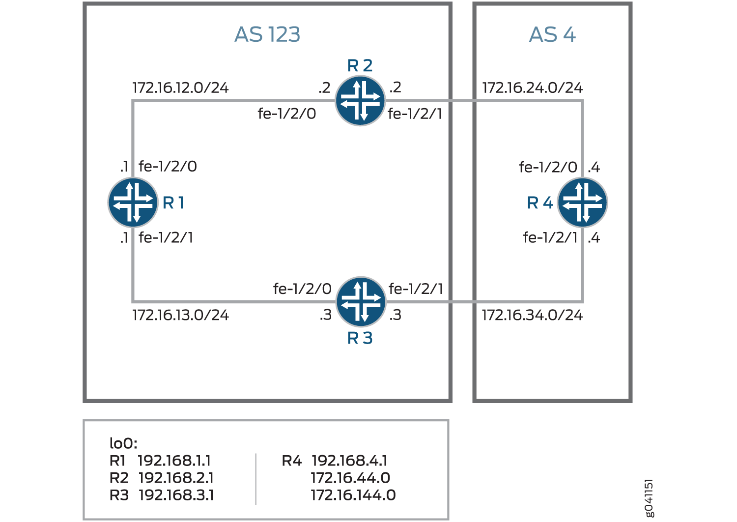
Figure 3 shows a typical network with internal peer sessions and multiple exit points to a neighboring autonomous system (AS).

Device R4 has multiple loopback interfaces configured to simulate advertised prefixes. The extra loopback interface addresses are 172.16.44.0/32 and 172.16.144.0/32. This example shows how to configure Device R4 to advertise a MED value of 30 to Device R3 for all routes except 172.16.144.0. For 172.16.144.0, a MED value of 10 is advertised to Device 3. A MED value of 20 is advertised to Device R2, regardless of the route prefix.
Configuration
- CLI Quick Configuration
- Configuring Device R1
- Configuring Device R2
- Configuring Device R3
- Configuring Device R4
CLI Quick Configuration
To quickly configure this example, copy the
following commands, paste them into a text file, remove any line breaks,
change any details necessary to match your network configuration,
and then copy and paste the commands into the CLI at the [edit] hierarchy level.
Device R1
set interfaces fe-1/2/0 unit 1 family inet address 172.16.12.1/24
set interfaces fe-1/2/1 unit 2 family inet address 172.16.13.1/24
set interfaces lo0 unit 1 family inet address 192.168.1.1/32
set protocols bgp group internal type internal
set protocols bgp group internal local-address 192.168.1.1
set protocols bgp group internal export send-direct
set protocols bgp group internal neighbor 192.168.2.1
set protocols bgp group internal neighbor 192.168.3.1
set protocols ospf area 0.0.0.0 interface lo0.1 passive
set protocols ospf area 0.0.0.0 interface fe-1/2/0.1
set protocols ospf area 0.0.0.0 interface fe-1/2/1.2
set policy-options policy-statement send-direct term 1 from protocol direct
set policy-options policy-statement send-direct term 1 then accept
set routing-options autonomous-system 123
set routing-options router-id 192.168.1.1
Device R2
set interfaces fe-1/2/0 unit 3 family inet address 172.16.12.2/24
set interfaces fe-1/2/1 unit 4 family inet address 172.16.24.2/24
set interfaces lo0 unit 2 family inet address 192.168.2.1/32
set protocols bgp group internal type internal
set protocols bgp group internal local-address 192.168.2.1
set protocols bgp group internal export send-direct
set protocols bgp group internal neighbor 192.168.1.1
set protocols bgp group internal neighbor 192.168.3.1
set protocols bgp group external type external
set protocols bgp group external export send-direct
set protocols bgp group external peer-as 4
set protocols bgp group external neighbor 172.16.24.4
set protocols ospf area 0.0.0.0 interface lo0.2 passive
set protocols ospf area 0.0.0.0 interface fe-1/2/0.3
set protocols ospf area 0.0.0.0 interface fe-1/2/1.4
set policy-options policy-statement send-direct term 1 from protocol direct
set policy-options policy-statement send-direct term 1 then accept
set routing-options autonomous-system 123
set routing-options router-id 192.168.2.1
Device R3
set interfaces fe-1/2/0 unit 5 family inet address 172.16.13.3/24
set interfaces fe-1/2/1 unit 6 family inet address 172.16.34.3/24
set interfaces lo0 unit 3 family inet address 192.168.3.1/32
set protocols bgp group internal type internal
set protocols bgp group internal local-address 192.168.3.1
set protocols bgp group internal export send-direct
set protocols bgp group internal neighbor 192.168.1.1
set protocols bgp group internal neighbor 192.168.2.1
set protocols bgp group external type external
set protocols bgp group external export send-direct
set protocols bgp group external peer-as 4
set protocols bgp group external neighbor 172.16.34.4
set protocols ospf area 0.0.0.0 interface lo0.3 passive
set protocols ospf area 0.0.0.0 interface fe-1/2/0.5
set protocols ospf area 0.0.0.0 interface fe-1/2/1.6
set policy-options policy-statement send-direct term 1 from protocol direct
set policy-options policy-statement send-direct term 1 then accept
set routing-options autonomous-system 123
set routing-options router-id 192.168.3.1
Device R4
set interfaces fe-1/2/0 unit 7 family inet address 172.16.24.4/24
set interfaces fe-1/2/1 unit 8 family inet address 172.16.34.4/24
set interfaces lo0 unit 4 family inet address 192.168.4.1/32
set interfaces lo0 unit 4 family inet address 172.16.44.0/32
set interfaces lo0 unit 4 family inet address 172.16.144.0/32
set protocols bgp group external type external
set protocols bgp group external export send-direct
set protocols bgp group external peer-as 123
set protocols bgp group external neighbor 172.16.34.3 export med-10
set protocols bgp group external neighbor 172.16.34.3 export med-30
set protocols bgp group external neighbor 172.16.24.2 metric-out 20
set policy-options policy-statement med-10 from route-filter 172.16.144.0/32 exact
set policy-options policy-statement med-10 then metric 10
set policy-options policy-statement med-10 then accept
set policy-options policy-statement med-30 from route-filter 0.0.0.0/0 longer
set policy-options policy-statement med-30 then metric 30
set policy-options policy-statement med-30 then accept
set policy-options policy-statement send-direct term 1 from protocol direct
set policy-options policy-statement send-direct term 1 then accept
set routing-options autonomous-system 4
set routing-options router-id 192.168.4.1
Configuring Device R1
Step-by-Step Procedure
The following example requires you to navigate various levels in the configuration hierarchy. For information about navigating the CLI, see Using the CLI Editor in Configuration Mode in the Junos OS CLI User Guide.
To configure Device R1:
Configure the device interfaces.
[edit interfaces fe-1/2/0 unit 1]
user@R1# set family inet address 172.16.12.1/24
[edit interfaces fe-1/2/1 unit 2]
user@R1# set family inet address 172.16.13.1/24
[edit interfaces lo0 unit 1]
user@R1# set family inet address 192.168.1.1/32
Configure BGP.
[edit protocols bgp group internal]
user@R1# set type internal
user@R1# set local-address 192.168.1.1
user@R1# set export send-direct
user@R1# set neighbor 192.168.2.1
user@R1# set neighbor 192.168.3.1
Configure OSPF.
[edit protocols ospf area 0.0.0.0]
user@R1# set interface lo0.1 passive
user@R1# set interface fe-1/2/0.1
user@R1# set interface fe-1/2/1.2
Configure a policy that accepts direct routes.
Other useful options for this scenario might be to accept routes learned through OSPF or local routes.
[edit policy-options policy-statement send-direct term 1]
user@R1# set from protocol direct
user@R1# set then accept
Configure the router ID and autonomous system (AS) number.
[edit routing-options]
user@R1# set autonomous-system 123
user@R1# set router-id 192.168.1.1
Results
From configuration mode, confirm your configuration
by entering the show interfaces, show protocols, show policy-options, and show routing-options commands. If the output does not display the intended configuration,
repeat the instructions in this example to correct the configuration.
user@R1# show interfaces
fe-1/2/0 {
    unit 1 {
        family inet {
            address 172.16.12.1/24;
        }
    }
}
fe-1/2/1 {
    unit 2 {
        family inet {
            address 172.16.13.1/24;
        }
    }
}
lo0 {
    unit 1 {
        family inet {
            address 192.168.1.1/32;
        }
    }
}
user@R1# show protocols
bgp {
    group internal {
        type internal;
        local-address 192.168.1.1;
        export send-direct;
        neighbor 192.168.2.1;
        neighbor 192.168.3.1;
    }
}
ospf {
    area 0.0.0.0 {
        interface lo0.1 {
            passive;
        }
        interface fe-1/2/0.1;
        interface fe-1/2/1.2;
    }
}
user@R1# show policy-options
policy-statement send-direct {
    term 1 {
        from protocol direct;
        then accept;
    }
}
user@R1# show routing-options
autonomous-system 123;
router-id 192.168.1.1;
If you are done configuring the device, enter commit from configuration mode.
Configuring Device R2
Step-by-Step Procedure
The following example requires you to navigate various levels in the configuration hierarchy. For information about navigating the CLI, see Using the CLI Editor in Configuration Mode in the Junos OS CLI User Guide.
To configure Device R2:
Configure the device interfaces.
[edit interfaces fe-1/2/0 unit 3]
user@R2# set family inet address 172.16.12.21/24
[edit interfaces fe-1/2/1 unit 4]
user@R2# set family inet address 172.16.24.2/24
[edit interfaces lo0 unit 2]
user@R2# set family inet address 192.168.2.1/32
Configure BGP.
[edit protocols bgp group internal]
user@R2# set type internal
user@R2# set local-address 192.168.2.1
user@R2# set export send-direct
user@R2# set neighbor 192.168.1.1
user@R2# set neighbor 192.168.3.1
[edit protocols bgp group external]
user@R2# set type external
user@R2# set export send-direct
user@R2# set peer-as 4
user@R2# set neighbor 172.16.24.4
Configure OSPF.
[edit protocols ospf area 0.0.0.0]
user@R2# set interface lo0.2 passive
user@R2# set interface fe-1/2/0.3
user@R2# set interface fe-1/2/1.4
Configure a policy that accepts direct routes.
Other useful options for this scenario might be to accept routes learned through OSPF or local routes.
[edit policy-options policy-statement send-direct term 1]
user@R2# set from protocol direct
user@R2# set then accept
Configure the router ID and autonomous system (AS) number.
[edit routing-options]
user@R2# set autonomous-system 123
user@R2# set router-id 192.168.2.1
Results
From configuration mode, confirm your configuration
by entering the show interfaces, show protocols, show policy-options, and show routing-options commands. If the output does not display the intended configuration,
repeat the instructions in this example to correct the configuration.
user@R2# show interfaces
fe-1/2/0 {
    unit 3 {
        family inet {
            address 172.16.12.2/24;
        }
    }
}
fe-1/2/1 {
    unit 4 {
        family inet {
            address 172.16.24.2/24;
        }
    }
}
lo0 {
    unit 2 {
        family inet {
            address 192.168.2.1/32;
        }
    }
}
user@R2# show protocols
bgp {
    group internal {
        type internal;
        local-address 192.168.2.1;
        export send-direct;
        neighbor 192.168.1.1;
        neighbor 192.168.3.1;
    }
    group external {
        type external;
        export send-direct;
        peer-as 4;
        neighbor 172.16.24.4;
    }
}
ospf {
    area 0.0.0.0 {
        interface lo0.2 {
            passive;
        }
        interface fe-1/2/0.3;
        interface fe-1/2/1.4;
    }
}
user@R2# show policy-options
policy-statement send-direct {
    term 1 {
        from protocol direct;
        then accept;
    }
}
user@R2# show routing-options
autonomous-system 123;
router-id 192.168.2.1;
If you are done configuring the device, enter commit from configuration mode.
Configuring Device R3
Step-by-Step Procedure
The following example requires you to navigate various levels in the configuration hierarchy. For information about navigating the CLI, see Using the CLI Editor in Configuration Mode in the Junos OS CLI User Guide.
To configure Device R3:
Configure the device interfaces.
[edit interfaces fe-1/2/0 unit 5]
user@R3# set family inet address 172.16.13.3/24
[edit interfaces fe-1/2/1 unit 6]
user@R3# set family inet address 172.16.34.3/24
[edit interfaces lo0 unit 3]
user@R3# set family inet address 192.168.3.1/32
Configure BGP.
[edit protocols bgp group internal]
user@R3# set type internal
user@R3# set local-address 192.168.3.1
user@R3# set export send-direct
user@R3# set neighbor 192.168.1.1
user@R3# set neighbor 192.168.2.1
[edit protocols bgp group external]
user@R3# set type external
user@R3# set export send-direct
user@R3# set peer-as 4
user@R3# set neighbor 172.16.34.4
Configure OSPF.
[edit protocols ospf area 0.0.0.0]
user@R3# set interface lo0.3 passive
user@R3# set interface fe-1/2/0.5
user@R3# set interface fe-1/2/1.6
Configure a policy that accepts direct routes.
Other useful options for this scenario might be to accept routes learned through OSPF or local routes.
[edit policy-options policy-statement send-direct term 1]
user@R3# set from protocol direct
user@R3# set then accept
Configure the router ID and autonomous system (AS) number.
[edit routing-options]
user@R3# set autonomous-system 123
user@R3# set router-id 192.168.3.1
Results
From configuration mode, confirm your configuration
by entering the show interfaces, show protocols, show policy-options, and show routing-options commands. If the output does not display the intended configuration,
repeat the instructions in this example to correct the configuration.
user@R3# show interfaces
fe-1/2/0 {
    unit 5 {
        family inet {
            address 172.16.13.3/24;
        }
    }
}
fe-1/2/1 {
    unit 6 {
        family inet {
            address 172.16.34.3/24;
        }
    }
}
lo0 {
    unit 3 {
        family inet {
            address 192.168.3.1/32;
        }
    }
}
user@R3# show protocols
bgp {
    group internal {
        type internal;
        local-address 192.168.3.1;
        export send-direct;
        neighbor 192.168.1.1;
        neighbor 192.168.2.1;
    }
    group external {
        type external;
        export send-direct;
        peer-as 4;
        neighbor 172.16.34.4;
    }
}
ospf {
    area 0.0.0.0 {
        interface lo0.3 {
            passive;
        }
        interface fe-1/2/0.5;
        interface fe-1/2/1.6;
    }
}
user@R3# show policy-options
policy-statement send-direct {
    term 1 {
        from protocol direct;
        then accept;
    }
}
user@R3# show routing-options
autonomous-system 123;
router-id 192.168.3.1;
If you are done configuring the device, enter commit from configuration mode.
Configuring Device R4
Step-by-Step Procedure
The following example requires you to navigate various levels in the configuration hierarchy. For information about navigating the CLI, see Using the CLI Editor in Configuration Mode in the Junos OS CLI User Guide.
To configure Device R4:
Configure the device interfaces.
[edit interfaces fe-1/2/0 unit 7]
user@R4# set family inet address 172.16.24.4/24
[edit interfaces fe-1/2/1 unit 8]
user@R4# set family inet address 172.16.34.4/24
[edit interfaces lo0 unit 4]
user@R4# set family inet address 192.168.4.1/32
user@R4# set family inet address 172.16.44.0/32
user@R4# set family inet address 172.16.144.0/32
Device R4 has multiple loopback interface addresses to simulate advertised prefixes.
Configure a policy that accepts direct routes.
Other useful options for this scenario might be to accept routes learned through OSPF or local routes.
[edit policy-options policy-statement send-direct term 1]
user@R4# set from protocol direct
user@R4# set then accept
Configure BGP.
[edit protocols bgp group external]
user@R4# set type external
user@R4# set export send-direct
user@R4# set peer-as 123
Configure the two MED policies.
[edit policy-options]
set policy-statement med-10 from route-filter 172.16.144.0/32 exact
set policy-statement med-10 then metric 10
set policy-statement med-10 then accept
set policy-statement med-30 from route-filter 0.0.0.0/0 longer
set policy-statement med-30 then metric 30
set policy-statement med-30 then accept
Configure the two EBGP neighbors, applying the two MED policies to Device R3, and a MED value of 20 to Device R2.
[edit protocols bgp group external]
user@R4# set neighbor 172.16.34.3 export med-10
user@R4# set neighbor 172.16.34.3 export med-30
user@R4# set neighbor 172.16.24.2 metric-out 20
Configure the router ID and autonomous system (AS) number.
[edit routing-options]
user@R4# set autonomous-system 4
user@R4# set router-id 192.168.4.1
Results
From configuration mode, confirm your configuration
by entering the show interfaces, show protocols, show policy-options, and show routing-options commands. If the output does not display the intended configuration,
repeat the instructions in this example to correct the configuration.
user@R4# show interfaces
fe-1/2/0 {
    unit 7 {
        family inet {
            address 172.16.24.4/24;
        }
    }
}
fe-1/2/1 {
    unit 8 {
        family inet {
            address 172.16.34.4/24;
        }
    }
}
lo0 {
    unit 4 {
        family inet {
            address 192.168.4.1/32;
            address 172.16.44.0/32;
            address 172.16.144.0/32;
        }
    }
}
user@R4# show protocols
bgp {
    group external {
        type external;
        export send-direct;
        peer-as 123;
        neighbor 172.16.24.2 {
            metric-out 20;
        }
        neighbor 172.16.34.3 {
            export [ med-10 med-30 ];
        }
    }
}
user@R4# show policy-options
policy-statement med-10 {
    from {
        route-filter 172.16.144.0/32 exact;
    }
    then {
        metric 10;
        accept;
    }
}
policy-statement med-30 {
    from {
        route-filter 0.0.0.0/0 longer;
    }
    then {
        metric 30;
        accept;
    }
}
policy-statement send-direct {
    term 1 {
        from protocol direct;
        then accept;
    }
}
user@R4# show routing-options
autonomous-system 4;
router-id 192.168.4.1;
If you are done configuring the device, enter commit from configuration mode.
Verification
Confirm that the configuration is working properly.
- Checking the Active Path from Device R1 to Device R4
- Verifying That Device R4 Is Sending Its Routes Correctly
Checking the Active Path from Device R1 to Device R4
Purpose
Verify that the active path goes through Device R2.
Action
From operational mode, enter the show route protocol
bgp command.
user@R1> show route protocol bgp
inet.0: 13 destinations, 19 routes (13 active, 0 holddown, 0 hidden)
+ = Active Route, - = Last Active, * = Both

172.16.12.0/24       [BGP/170] 4d 01:13:32, localpref 100, from 192.168.2.1
                      AS path: I
                    > to 172.16.12.2 via fe-1/2/0.1
172.16.13.0/24       [BGP/170] 3d 05:36:10, localpref 100, from 192.168.3.1
                      AS path: I
                    > to 172.16.13.3 via fe-1/2/1.2
172.16.24.0/24       [BGP/170] 4d 01:13:32, localpref 100, from 192.168.2.1
                      AS path: I
                    > to 172.16.12.2 via fe-1/2/0.1
172.16.34.0/24       [BGP/170] 3d 05:36:10, localpref 100, from 192.168.3.1
                      AS path: I
                    > to 172.16.13.3 via fe-1/2/1.2
172.16.44.0/32     *[BGP/170] 00:06:03, MED 20, localpref 100, from 192.168.2.1
                      AS path: 4 I
                    > to 172.16.12.2 via fe-1/2/0.1
172.16.144.0/32 *[BGP/170] 00:06:03, MED 10, localpref 100, from 192.168.3.1
                      AS path: 4 I
                    > to 172.16.13.3 via fe-1/2/1.2
192.168.2.1/32      [BGP/170] 4d 01:13:32, localpref 100, from 192.168.2.1
                      AS path: I
                    > to 172.16.12.2 via fe-1/2/0.1
192.168.3.1/32      [BGP/170] 3d 05:36:10, localpref 100, from 192.168.3.1
                      AS path: I
                    > to 172.16.13.3 via fe-1/2/1.2
192.168.4.1/32     *[BGP/170] 00:06:03, MED 20, localpref 100, from 192.168.2.1
                      AS path: 4 I
                    > to 172.16.12.2 via fe-1/2/0.1
Meaning
The output shows that the preferred path to the routes advertised by Device R4 is through Device R2 for all routes except 172.16.144.0/32. For 172.16.144.0/32, the preferred path is through Device R3.
Verifying That Device R4 Is Sending Its Routes Correctly
Purpose
Make sure that Device R4 is sending update messages with a value of 20 to Device R2 and a value of 30 to Device R3.
Action
From operational mode, enter the show route advertising-protocol
bgp command.
user@R4> show route advertising-protocol bgp 172.16.24.2
inet.0: 11 destinations, 13 routes (11 active, 0 holddown, 0 hidden)
  Prefix                  Nexthop              MED     Lclpref    AS path
* 172.16.24.0/24           Self                 20                 I
* 172.16.34.0/24           Self                 20                 I
* 172.16.44.0/32          Self                 20                 I
* 172.16.144.0/32      Self                 20                 I
* 192.168.4.1/32          Self                 20                 I
user@R4> show route advertising-protocol bgp 172.16.34.3
inet.0: 11 destinations, 13 routes (11 active, 0 holddown, 0 hidden)
  Prefix                  Nexthop              MED     Lclpref    AS path
* 172.16.24.0/24           Self                 30                 I
* 172.16.34.0/24           Self                 30                 I
* 172.16.44.0/32          Self                 30                 I
* 172.16.144.0/32      Self                 10                 I
* 192.168.4.1/32          Self                 30                 I
Meaning
The MED column shows that Device R4 is sending the correct MED values to its two EBGP neighbors.
Example: Configuring the MED Using Communities
Set the multiple exit discriminator (MED) metric to 20 for all routes from a particular community.
[edit]
routing-options {
    router-id 10.0.0.1;
    autonomous-system 23;
}
policy-options {
    policy-statement from-otago {
        from community otago;
        then metric 20;
    }
    community otago members [56:2379 23:46944];
}
protocols {
    bgp {
        import from-otago;
        group 23 {
            type external;
            peer-as 56;
            neighbor 192.168.0.1 {
                traceoptions {
                    file bgp-log-peer;
                    flag packets;
                }
                log-updown;
            }
        }
    }
}
Example: Associating the MED Path Attribute with the IGP Metric and Delaying MED Updates
This example shows how to associate the multiple exit discriminator (MED) path attribute with the interior gateway protocol (IGP) metric, and configure a timer to delay update of the MED attribute.
Requirements
No special configuration beyond device initialization is required before you configure this example.
Overview
BGP can be configured to advertise the MED attribute for a route based on the IGP distance of its internal BGP (IBGP) route next-hop. The IGP metric enables internal routing to follow the shortest path according to the administrative setup. In some deployments, it might be ideal to communicate IGP shortest-path knowledge to external BGP (EBGP) peers in a neighboring autonomous system (AS). This allows those EBGP peers to forward traffic into your AS using the shortest paths possible.
Routes learned from an EBGP peer usually have a next hop on
a directly connected interface, and thus the IGP value is equal to
zero. Zero is the value advertised. The IGP metric is a nonzero value
when a BGP peer sends third-party next hops that require the local
system to perform next-hop resolution—IBGP configurations, configurations
within confederation peers, or EBGP configurations that include the multihop statement. In these scenarios, it might make sense
to associate the MED value with the IGP metric by including the
metric-out minimum-igp or
metric-out igp option.
The drawback of associating the MED with the IGP metric is the
risk of excessive route advertisements when there are IGP instabilities
in the network. Configuring a delay for the MED update provides a
mechanism to reduce route advertisements in such scenarios. The delay
works by slowing down MED updates when the IGP metric for the next
hop changes. The approach uses a timer to periodically advertise MED
updates. When the timer expires, the MED attribute for routes with metric-out igp delay-updates configured is updated to the current
IGP metric of the next hop. The BGP-enabled device sends out advertisements
for routes for which the MED attribute has changed.
The delay-updates option identifies the BGP groups
(or peers) for which the MED updates must be suppressed. The time
for advertising MED updates is set to 10 minutes by default. You can
increase the interval up to 600 minutes by including the
med-igp-update-interval
statement in the routing-options configuration.
If you have nonstop active routing (NSR) enabled and a switchover occurs, the delayed MED updates might be advertised as soon as the switchover occurs.
When you configure the metric-out igp option, the
IGP metric directly tracks the IGP cost to the IBGP peer. When the
IGP cost goes down, so does the advertised MED value. Conversely,
when the IGP cost goes up, the MED value goes up as well.
When you configure the metric-out minimum-igp option,
the advertised MED value changes only when the IGP cost to the IBGP
peer goes down. An increase in the IGP cost does not affect the MED
value. The router monitors and remembers the lowest IGP cost until
the routing process (rpd) is restarted. The BGP peer sends an update
only if the MED is lower than the previously advertised value or another
attribute associated with the route has changed, or if the BGP peer
is responding to a refresh route request.
This example uses the metric statement in the OSPF
configuration to demonstrate that when the IGP metric changes, the
MED also changes after the configured delay interval. The OSPF metric
can range from 1 through 65,535.
Figure 4 shows the sample topology.
In this example, the MED value advertised by Device R1 is associated with the IGP running in AS 1. The MED value advertised by Device R1 impacts the decisions of the neighboring AS (AS 2) when AS 2 is forwarding traffic into AS 1.
Configuration
CLI Quick Configuration
To quickly configure this example, copy the
following commands, paste them into a text file, remove any line breaks,
change any details necessary to match your network configuration,
and then copy and paste the commands into the CLI at the [edit] hierarchy level.
Device R1
               set interfaces fe-1/2/0 unit 2 description R1->R2


               set interfaces fe-1/2/0 unit 2 family inet address 10.0.0.1/30


               set interfaces fe-1/2/1 unit 7 description R1->R4


               set interfaces fe-1/2/1 unit 7 family inet address 172.16.0.1/30


               set interfaces lo0 unit 1 family inet address 192.168.0.1/32


               set protocols bgp group internal type internal


               set protocols bgp group internal local-address 192.168.0.1


               set protocols bgp group internal export send-direct


               set protocols bgp group internal neighbor 192.168.0.2


               set protocols bgp group internal neighbor 192.168.0.3


               set protocols bgp group external type external


               set protocols bgp group external metric-out igp delay-med-update


               set protocols bgp group external export send-direct


               set protocols bgp group external peer-as 2


               set protocols bgp group external neighbor 172.16.0.2


               set protocols ospf area 0.0.0.0 interface fe-1/2/0.2 metric 600


               set protocols ospf area 0.0.0.0 interface lo0.1 passive


               set policy-options policy-statement send-direct term 1 from protocol direct


               set policy-options policy-statement send-direct term 1 then accept


               set routing-options med-igp-update-interval 12


               set routing-options router-id 192.168.0.1


               set routing-options autonomous-system 1
Device R2
               set interfaces fe-1/2/0 unit 1 description R2->R1


               set interfaces fe-1/2/0 unit 1 family inet address 10.0.0.2/30


               set interfaces fe-1/2/1 unit 4 description R2->R3


               set interfaces fe-1/2/1 unit 4 family inet address 10.0.2.2/30


               set interfaces lo0 unit 2 family inet address 192.168.0.2/32


               set protocols bgp group internal type internal


               set protocols bgp group internal local-address 192.168.0.2


               set protocols bgp group internal export send-direct


               set protocols bgp group internal neighbor 192.168.0.1


               set protocols bgp group internal neighbor 192.168.0.3


               set protocols ospf area 0.0.0.0 interface fe-1/2/0.1


               set protocols ospf area 0.0.0.0 interface fe-1/2/1.4


               set protocols ospf area 0.0.0.0 interface lo0.2 passive


               set policy-options policy-statement send-direct term 1 from protocol direct


               set policy-options policy-statement send-direct term 1 then accept


               set routing-options router-id 192.168.0.2


               set routing-options autonomous-system 1
Device R3
               set interfaces fe-1/2/0 unit 3 description R3->R2


               set interfaces fe-1/2/0 unit 3 family inet address 10.0.2.1/30


               set interfaces fe-1/2/1 unit 5 description R3->R5


               set interfaces fe-1/2/1 unit 5 family inet address 172.16.0.5/30


               set interfaces lo0 unit 3 family inet address 192.168.0.3/32


               set protocols bgp group internal type internal


               set protocols bgp group internal local-address 192.168.0.3


               set protocols bgp group internal export send-direct


               set protocols bgp group internal neighbor 192.168.0.1


               set protocols bgp group internal neighbor 192.168.0.2


               set protocols bgp group external type external


               set protocols bgp group external export send-direct


               set protocols bgp group external peer-as 2


               set protocols bgp group external neighbor 172.16.0.6


               set protocols ospf area 0.0.0.0 interface fe-1/2/0.3


               set protocols ospf area 0.0.0.0 interface lo0.3 passive


               set policy-options policy-statement send-direct term 1 from protocol direct


               set policy-options policy-statement send-direct term 1 then accept


               set routing-options router-id 192.168.0.3


               set routing-options autonomous-system 1
Device R4
               set interfaces fe-1/2/0 unit 8 description R4->R1


               set interfaces fe-1/2/0 unit 8 family inet address 172.16.0.2/30


               set interfaces fe-1/2/1 unit 9 description R4->R5


               set interfaces fe-1/2/1 unit 9 family inet address 10.0.4.1/30


               set interfaces fe-1/2/2 unit 13 description R4->R6


               set interfaces fe-1/2/2 unit 13 family inet address 172.16.0.9/30


               set interfaces lo0 unit 4 family inet address 192.168.0.4/32


               set protocols bgp group internal type internal


               set protocols bgp group internal local-address 192.168.0.4


               set protocols bgp group internal export send-direct


               set protocols bgp group internal neighbor 192.168.0.5


               set protocols bgp group external type external


               set protocols bgp group external export send-direct


               set protocols bgp group external neighbor 172.16.0.10 peer-as 3


               set protocols bgp group external neighbor 172.16.0.1 peer-as 1


               set protocols ospf area 0.0.0.0 interface fe-1/2/1.9


               set protocols ospf area 0.0.0.0 interface lo0.4 passive


               set policy-options policy-statement send-direct term 1 from protocol direct


               set policy-options policy-statement send-direct term 1 then accept


               set routing-options router-id 192.168.0.4


               set routing-options autonomous-system 2
Device R5
               set interfaces fe-1/2/0 unit 6 description R5->R3


               set interfaces fe-1/2/0 unit 6 family inet address 172.16.0.6/30


               set interfaces fe-1/2/1 unit 10 description R5->R4


               set interfaces fe-1/2/1 unit 10 family inet address 10.0.4.2/30


               set interfaces fe-1/2/2 unit 11 description R5->R8


               set interfaces fe-1/2/2 unit 11 family inet address 172.16.0.13/30


               set interfaces lo0 unit 5 family inet address 192.168.0.5/32


               set protocols bgp group internal type internal


               set protocols bgp group internal local-address 192.168.0.5


               set protocols bgp group internal export send-direct


               set protocols bgp group internal neighbor 192.168.0.4


               set protocols bgp group external type external


               set protocols bgp group external export send-direct


               set protocols bgp group external neighbor 172.16.0.5 peer-as 1


               set protocols bgp group external neighbor 172.16.0.14 peer-as 3


               set protocols ospf area 0.0.0.0 interface fe-1/2/1.10


               set protocols ospf area 0.0.0.0 interface lo0.5 passive


               set policy-options policy-statement send-direct term 1 from protocol direct


               set policy-options policy-statement send-direct term 1 then accept


               set routing-options router-id 192.168.0.5


               set routing-options autonomous-system 2
Device R6
               set interfaces fe-1/2/0 unit 14 description R6->R4


               set interfaces fe-1/2/0 unit 14 family inet address 172.16.0.10/30


               set interfaces fe-1/2/1 unit 15 description R6->R7


               set interfaces fe-1/2/1 unit 15 family inet address 10.0.6.1/30


               set interfaces lo0 unit 6 family inet address 192.168.0.6/32


               set protocols bgp group internal type internal


               set protocols bgp group internal local-address 192.168.0.6


               set protocols bgp group internal export send-direct


               set protocols bgp group internal neighbor 192.168.0.7


               set protocols bgp group internal neighbor 192.168.0.8


               set protocols bgp group external type external


               set protocols bgp group external export send-direct


               set protocols bgp group external peer-as 2


               set protocols bgp group external neighbor 172.16.0.9 peer-as 2


               set protocols ospf area 0.0.0.0 interface fe-1/2/1.15


               set protocols ospf area 0.0.0.0 interface lo0.6 passive


               set policy-options policy-statement send-direct term 1 from protocol direct


               set policy-options policy-statement send-direct term 1 then accept


               set routing-options router-id 192.168.0.6


               set routing-options autonomous-system 3
Device R7
               set interfaces fe-1/2/0 unit 16 description R7->R6


               set interfaces fe-1/2/0 unit 16 family inet address 10.0.6.2/30


               set interfaces fe-1/2/1 unit 17 description R7->R8


               set interfaces fe-1/2/1 unit 17 family inet address 10.0.7.2/30


               set interfaces lo0 unit 7 family inet address 192.168.0.7/32


               set protocols bgp group internal type internal


               set protocols bgp group internal local-address 192.168.0.7


               set protocols bgp group internal export send-direct


               set protocols bgp group internal neighbor 192.168.0.6


               set protocols bgp group internal neighbor 192.168.0.8


               set protocols ospf area 0.0.0.0 interface fe-1/2/0.16


               set protocols ospf area 0.0.0.0 interface fe-1/2/1.17


               set protocols ospf area 0.0.0.0 interface lo0.7 passive


               set policy-options policy-statement send-direct term 1 from protocol direct


               set policy-options policy-statement send-direct term 1 then accept


               set routing-options router-id 192.168.0.7


               set routing-options autonomous-system 3
Device R8
               set interfaces fe-1/2/0 unit 12 description R8->R5


               set interfaces fe-1/2/0 unit 12 family inet address 172.16.0.14/30


               set interfaces fe-1/2/1 unit 18 description R8->R7


               set interfaces fe-1/2/1 unit 18 family inet address 10.0.7.1/30


               set interfaces lo0 unit 8 family inet address 192.168.0.8/32


               set protocols bgp group internal type internal


               set protocols bgp group internal local-address 192.168.0.8


               set protocols bgp group internal export send-direct


               set protocols bgp group internal neighbor 192.168.0.6


               set protocols bgp group internal neighbor 192.168.0.7


               set protocols bgp group external type external


               set protocols bgp group external export send-direct


               set protocols bgp group external peer-as 2


               set protocols bgp group external neighbor 172.16.0.13 peer-as 2


               set protocols ospf area 0.0.0.0 interface fe-1/2/1.18


               set protocols ospf area 0.0.0.0 interface lo0.8 passive


               set policy-options policy-statement send-direct term 1 from protocol direct


               set policy-options policy-statement send-direct term 1 then accept


               set routing-options router-id 192.168.0.8


               set routing-options autonomous-system 3
Configuring Device R1
Step-by-Step Procedure
The following example requires you to navigate various levels in the configuration hierarchy. For information about navigating the CLI, see Using the CLI Editor in Configuration Mode in the Junos OS CLI User Guide.
To configure Device R1:
-
Configure the interfaces.
[edit interfaces fe-1/2/0 unit 2] user@R1# set description R1->R2 user@R1# set family inet address 10.0.0.1/30 [edit interfaces fe-1/2/1 unit 7] user@R1# set description R1->R4 user@R1# set family inet address 172.16.0.1/30 [edit interfaces lo0 unit 1] user@R1# set family inet address 192.168.0.1/32 -
Configure IBGP.
[edit protocols bgp group internal] user@R1# set type internal user@R1# set local-address 192.168.0.1 user@R1# set export send-direct user@R1# set neighbor 192.168.0.2 user@R1# set neighbor 192.168.0.3 -
Configure EBGP.
[edit protocols bgp group external] user@R1# set type external user@R1# set export send-direct user@R1# set peer-as 2 user@R1# set neighbor 172.16.0.2 -
Associate the MED value with the IGP metric.
[edit protocols bgp group external]
user@R1# set metric-out igp delay-med-update
The default for the MED update is 10 minutes when you include the
delay-med-updateoption. When you exclude thedelay-med-updateoption, the MED update occurs immediately after the IGP metric changes. -
(Optional) Configure the update interval for the MED update.
[edit routing-options]
user@R1# set med-igp-update-interval 12
You can configure the interval from 10 minutes through 600 minutes.
-
Configure OSPF.
[edit protocols ospf area 0.0.0.0]
user@R1# set interface fe-1/2/0.2 metric 600
user@R1# set interface lo0.1 passive
The
metricstatement is used here to demonstrate what happens when the IGP metric changes. -
Configure a policy that accepts direct routes.
Other useful options for this scenario might be to accept routes learned through OSPF or local routes.
[edit policy-options policy-statement send-direct term 1] user@R1# set from protocol direct user@R1# set then accept -
Configure the router ID and autonomous system (AS) number.
[edit routing-options]
user@R1# set router-id 192.168.0.1
user@R1# set autonomous-system 1
Results
From configuration mode, confirm your configuration
by entering the show interfaces, show policy-options, show protocols, and show routing-options commands.
If the output does not display the intended configuration, repeat
the instructions in this example to correct the configuration.
user@R1# show interfaces
fe-1/2/0 {
    unit 2 {
        description R1->R2;
        family inet {
            address 10.0.0.1/30;
        }
    }
}
fe-1/2/1 {
    unit 7 {
        description R1->R4;
        family inet {
            address 172.16.0.1/30;
        }
    }
}
lo0 {
    unit 1 {
        family inet {
            address 192.168.0.1/32;
        }
    }
}
user@R1# show policy-options
policy-statement send-direct {
    term 1 {
        from protocol direct;
        then accept;
    }
}
user@R1# show protocols
bgp {
    group internal {
        type internal;
        local-address 192.168.0.1;
        export send-direct;
        neighbor 192.168.0.2;
        neighbor 192.168.0.3;
    }
    group external {
        type external;
        metric-out igp delay-med-update;
        export send-direct;
        peer-as 2;
        neighbor 172.16.0.2;
    }
}
ospf {
    area 0.0.0.0 {
        interface fe-1/2/0.2 {
            metric 600;
        }
        interface lo0.1 {
            passive;
        }
    }
}
user@R1# show routing-options
med-igp-update-interval 12;
router-id 192.168.0.1;
autonomous-system 1;
If you are done configuring the device, enter commit from configuration mode. Repeat the configuration steps on the other
devices in the topology, as needed for your network.
Verification
Confirm that the configuration is working properly.
- Checking the BGP Advertisements
- Verifying That the MED Value Changes When the OSPF Metric Changes
- Testing the minimum-igp Setting
Checking the BGP Advertisements
Purpose
Verify that Device R1 is advertising to Device R4 a BGP MED value that reflects the IGP metric.
Action
From operational mode, enter the show route advertising-protocol
bgp command.
user@R1> show route advertising-protocol bgp 172.16.0.2
inet.0: 19 destinations, 33 routes (19 active, 0 holddown, 0 hidden)
  Prefix                  Nexthop              MED     Lclpref    AS path
* 10.0.0.0/30             Self                 0                  I
* 172.16.0.0/30           Self                 0                  I
* 172.16.0.4/30           Self                 601                I
* 192.168.0.1/32          Self                 0                  I
Meaning
The 601 value in the MED column shows that the MED value has been updated to reflect the configured OSPF metric.
Verifying That the MED Value Changes When the OSPF Metric Changes
Purpose
Make sure that when you raise the OSPF metric to 700, the MED value is updated to reflect this change.
Action
From configuration mode, enter the set protocols
ospf area 0 interface fe-1/2/0.2 metric 700 command.
user@R1# set protocols ospf area 0 interface fe-1/2/0.2 metric 700
user@R1# commit
After waiting 12 minutes (the configured delay period), enter
the show route advertising-protocol bgp command from operational
mode.
user@R1> show route advertising-protocol bgp 172.16.0.2
inet.0: 19 destinations, 33 routes (19 active, 0 holddown, 0 hidden)
  Prefix                  Nexthop              MED     Lclpref    AS path
* 10.0.0.0/30             Self                 0                  I
* 172.16.0.0/30           Self                 0                  I
* 172.16.0.4/30           Self                 701                I
* 192.168.0.1/32          Self                 0                  I
Meaning
The 701 value in the MED column shows that the MED value has been updated to reflect the configured OSPF metric.
Testing the minimum-igp Setting
Purpose
Change the configuration to use the minimum-igp statement instead of the igp statement. When you increase
the OSPF metric, the MED value remains unchanged, but when you decrease
the OSPF metric, the MED value reflects the new OSPF metric.
Action
From configuration mode, delete the igp statement,
add the minimum-igp statement, and increase the OSPF metric.
user@R1# delete protocols bgp group external metric-out igp
user@R1# set protocols bgp group external metric-out minimum-igp
user@R1# set protocols ospf area 0 interface fe-1/2/0.2 metric 800
user@R1# commit
From operational mode, enter the show route advertising-protocol
bgp command to make sure that the MED value does not change.
user@R1> show route advertising-protocol bgp 172.16.0.2
inet.0: 19 destinations, 33 routes (19 active, 0 holddown, 0 hidden)
  Prefix                  Nexthop              MED     Lclpref    AS path
* 10.0.0.0/30             Self                 0                  I
* 172.16.0.0/30           Self                 0                  I
* 172.16.0.4/30           Self                 701                I
* 192.168.0.1/32          Self                 0                  I
From configuration mode, decrease the OSPF metric.
user@R1# set protocols ospf area 0 interface fe-1/2/0.2 metric 20
user@R1# commit
From operational mode, enter the show route advertising-protocol
bgp command to make sure that the MED value does change.
user@R1> show route advertising-protocol bgp 172.16.0.2
inet.0: 19 destinations, 33 routes (19 active, 0 holddown, 0 hidden)
  Prefix                  Nexthop              MED     Lclpref    AS path
* 10.0.0.0/30             Self                 0                  I
* 172.16.0.0/30           Self                 0                  I
* 172.16.0.4/30           Self                 21                 I
* 192.168.0.1/32          Self                 0                  I
Meaning
When the minimum-igp statement is configured,
the MED value changes only when a shorter path is available.