ON THIS PAGE
Example: Configuring a Multi-Level IS-IS Topology to Control Interarea Flooding
This example shows how to configure a multi-level IS-IS topology.
Requirements
No special configuration beyond device initialization is required before configuring this example.
Overview
Like OSPF, the IS-IS protocol supports the partitioning of a routing domain into multiple areas with levels that control interarea flooding. The use of multiple levels improves protocol scalability, as Level 2 (backbone) link-state PDUs are normally not flooded into a Level 1 area.
An IS-IS Level 2 area is analogous to the OSPF backbone area (0), while a Level 1 area operates much like an OSPF totally stubby area, in that a default route is normally used to reach both inter-level and AS external routes.
Unlike OSPF, IS-IS area boundaries occur between routers, such that a given routing device is always wholly contained within a particular area. Level 1 adjacencies can be formed between routers that share a common area number, while a Level 2 adjacency can be formed between routers that might or might not share an area number.
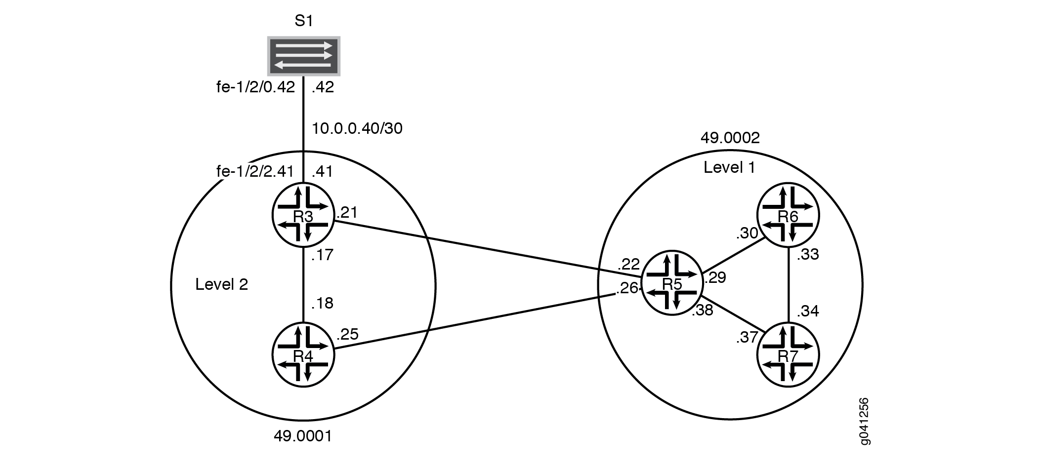
Figure 1 shows the topology used in this example.
CLI Quick Configuration shows the configuration for all of the devices in Figure 1. The section #configuration69__isis-multi-level-step-by-step describes the steps on Device R5.
This example has the following characteristics:
-
Device R5 functions as a Level 1/Level 2 router to interconnect the Level 2 backbone area 49.0001 and the Level 1 area 49.0002 containing Device R6 and Device R7.
-
The system ID is based on the devices’ IPv4 lo0 addresses.
-
Loss of any individual interface does not totally disrupt the IS-IS operation.
-
The IPv4 lo0 addresses of all routers are reachable through IS-IS.
-
The link between Device R3 and Device S1 appears in area 49.0001 as an intra-area route. No IS-IS adjacencies can be established on this interface. This is accomplished by configuring the
passivestatement on Device R3’s interface to Device S1. -
The loopback addresses of Level 2 devices do not appear in a Level 1 area.
-
There is only one adjacency for each device pairing.
Topology
Configuration
Procedure
CLI Quick Configuration
To quickly configure this example, copy the following commands, paste them
into a text file, remove any line breaks, change any details necessary to
match your network configuration, and then copy and paste the commands into
the CLI at the [edit] hierarchy level.
Device R3
set interfaces fe-1/2/0 unit 0 description to-R4
set interfaces fe-1/2/0 unit 0 family inet address 10.0.0.17/30
set interfaces fe-1/2/0 unit 0 family iso
set interfaces fe-1/2/1 unit 0 description to-R5
set interfaces fe-1/2/1 unit 0 family inet address 10.0.0.21/30
set interfaces fe-1/2/1 unit 0 family iso
set interfaces fe-1/2/2 unit 0 family inet address 10.0.0.41/30
set interfaces fe-1/2/2 unit 0 description to-S1
set interfaces lo0 unit 0 family inet address 192.168.0.3/32
set interfaces lo0 unit 0 family iso address 49.0001.1921.6800.0003.00
set protocols isis interface fe-1/2/0.0 level 1 disable
set protocols isis interface fe-1/2/1.0 level 1 disable
set protocols isis interface lo0.0 level 1 disable
set protocols isis interface fe-1/2/2.0 passive
Device R4
set interfaces fe-1/2/0 unit 0 description to-R3
set interfaces fe-1/2/0 unit 0 family inet address 10.0.0.18/30
set interfaces fe-1/2/0 unit 0 family iso
set interfaces fe-1/2/1 unit 0 description to-R5
set interfaces fe-1/2/1 unit 0 family inet address 10.0.0.25/30
set interfaces fe-1/2/1 unit 0 family iso
set interfaces lo0 unit 0 family inet address 192.168.0.4/32
set interfaces lo0 unit 0 family iso address 49.0001.0192.0168.0004.00
set protocols isis interface fe-1/2/0.0 level 1 disable
set protocols isis interface fe-1/2/1.0 level 1 disable
set protocols isis interface lo0.0 level 1 disable
Device R5
set interfaces fe-1/2/0 unit 0 description to-R3
set interfaces fe-1/2/0 unit 0 family inet address 10.0.0.22/30
set interfaces fe-1/2/0 unit 0 family iso
set interfaces fe-1/2/1 unit 0 description to-R4
set interfaces fe-1/2/1 unit 0 family inet address 10.0.0.26/30
set interfaces fe-1/2/1 unit 0 family iso
set interfaces fe-1/2/2 unit 0 description to-R6
set interfaces fe-1/2/2 unit 0 family inet address 10.0.0.29/30
set interfaces fe-1/2/2 unit 0 family iso
set interfaces fe-1/2/3 unit 0 description to-R7
set interfaces fe-1/2/3 unit 0 family inet address 10.0.0.38/30
set interfaces fe-1/2/3 unit 0 family iso
set interfaces lo0 unit 0 family inet address 192.168.0.5/32
set interfaces lo0 unit 0 family iso address 49.0002.0192.0168.0005.00
set protocols isis interface fe-1/2/0.0 level 1 disable
set protocols isis interface fe-1/2/1.0 level 1 disable
set protocols isis interface fe-1/2/2.0 level 2 disable
set protocols isis interface fe-1/2/3.0 level 2 disable
set protocols isis interface lo0.0 level 1 disable
Device R6
set interfaces fe-1/2/0 unit 0 description to-R5
set interfaces fe-1/2/0 unit 0 family inet address 10.0.0.30/30
set interfaces fe-1/2/0 unit 0 family iso
set interfaces fe-1/2/1 unit 0 description to-R7
set interfaces fe-1/2/1 unit 0 family inet address 10.0.0.33/30
set interfaces fe-1/2/1 unit 0 family iso
set interfaces lo0 unit 0 family inet address 192.168.0.6/32
set interfaces lo0 unit 0 family iso address 49.0002.0192.0168.0006.00
set protocols isis interface fe-1/2/0.0 level 2 disable
set protocols isis interface fe-1/2/1.0 level 2 disable
set protocols isis interface lo0.0 level 2 disable
Device R7
set interfaces fe-1/2/0 unit 0 description to-R6
set interfaces fe-1/2/0 unit 0 family inet address 10.0.0.34/30
set interfaces fe-1/2/0 unit 0 family iso
set interfaces fe-1/2/1 unit 0 description to-R5
set interfaces fe-1/2/1 unit 0 family inet address 10.0.0.37/30
set interfaces fe-1/2/1 unit 0 family iso
set interfaces lo0 unit 0 family inet address 192.168.0.7/32
set interfaces lo0 unit 0 family iso address 49.0002.0192.0168.0007.00
set protocols isis interface fe-1/2/0.0 level 2 disable
set protocols isis interface fe-1/2/1.0 level 2 disable
set protocols isis interface lo0.0 level 2 disable
Device S1
set interfaces fe-1/2/0 unit 0 family inet address 10.0.0.42/30
set interfaces fe-1/2/0 unit 0 description to-R3
Step-by-Step Procedure
The following example requires you to navigate various levels in the configuration hierarchy. For information about navigating the CLI, see Using the CLI Editor in Configuration Mode in the CLI User Guide.
To configure multi-level IS-IS:
-
Configure the network interfaces.
Enable IS-IS on the interfaces by Including the ISO address family on each interface.
[edit interfaces]
user@R5# set fe-1/2/0 unit 0 description to-R3
user@R5# set fe-1/2/0 unit 0 family inet address 10.0.0.22/30
user@R5# set fe-1/2/0 unit 0 family iso
user@R5# set fe-1/2/1 unit 0 description to-R4
user@R5# set fe-1/2/1 unit 0 family inet address 10.0.0.26/30
user@R5# set fe-1/2/1 unit 0 family iso
user@R5# set fe-1/2/2 unit 0 description to-R6
user@R5# set fe-1/2/2 unit 0 family inet address 10.0.0.29/30
user@R5# set fe-1/2/2 unit 0 family iso
user@R5# set fe-1/2/3 unit 0 description to-R7
user@R5# set fe-1/2/3 unit 0 family inet address 10.0.0.38/30
user@R5# set fe-1/2/3 unit 0 family iso
-
Configure two loopback interface addresses.
One address is for IPv4.
The other is for the IS-IS area 49.0002 so that Device R5 can form adjacencies with the other Level 1 devices in area 49.0002. Even though Device R5’s NET identifies itself as belonging to the Level 1 area 49.0002, its loopback interface is not configured as a Level 1 interface. Doing so would cause the route to Device R5’s loopback to be injected into the Level 1 area.
[edit interfaces lo0 unit 0]
user@R5# set family inet address 192.168.0.5/32
user@R5# set family iso address 49.0002.0192.0168.0005.00
-
Specify the IS-IS level on a per-interface basis.
Device R5 becomes adjacent to the other routing devices on the same level on each link.
By default, IS-IS is enabled for IS-IS areas on all interfaces on which the ISO protocol family is enabled (at the
[edit
                                    interfaces interface-name unit
                                        logical-unit-number]
hierarchy level). To disable IS-IS at any particular level on an interface, include thedisablestatement.Device R5’s loopback interface is configured to run Level 2 only. If Level 1 operation were enabled on lo0.0, Device R5 would include its loopback address in its Level 1 link-state PDU, which is incorrect for this example in which the loopback addresses of Level 2 devices must not appear in a Level 1 area.
Unlike OSPF, you must explicitly list the router’s lo0 interface at the
[edit protocols isis]hierarchy level, because this interface is the source of the router’s NET, and therefore must be configured as an IS-IS interface. In IS-IS, the lo0 interface operates in the passive mode by default, which is ideal because adjacency formation can never occur on a virtual interface.[edit protocols isis] user@R5# set interface fe-1/2/0.0 level 1 disable user@R5# set interface fe-1/2/1.0 level 1 disable user@R5# set interface fe-1/2/2.0 level 2 disable user@R5# set interface fe-1/2/3.0 level 2 disable user@R5# set interface lo0.0 level 1 disable
Results
From configuration mode, confirm your configuration by entering the
show interfaces and show protocols
commands. If the output does not display the intended configuration, repeat
the instructions in this example to correct the configuration.
user@R5# show interfaces
fe-1/2/0 {
    unit 0{
        description to-R3;
        family inet {
            address 10.0.0.22/30;
        }
        family iso;
    }
}
fe-1/2/1 {
    unit 0 {
        description to-R4;
        family inet {
            address 10.0.0.26/30;
        }
        family iso;
    }
}
fe-1/2/2 {
    unit 0 {
        description to-R6;
        family inet {
            address 10.0.0.29/30;
        }
        family iso;
    }
}
fe-1/2/3 {
    unit 0 {
        description to-R7;
        family inet {
            address 10.0.0.38/30;
        }
        family iso;
    }
}
lo0 {
    unit 0 {
        family inet {
            address 192.168.0.5/32;
        }
        family iso {
            address 49.0002.0192.0168.0005.00;
        }
    }
}
user@R5# show protocols
isis {
    interface fe-1/2/0.0 {
        level 1 disable;
    }
    interface fe-1/2/1.0 {
        level 1 disable;
    }
    interface fe-1/2/2.0 {
        level 2 disable;
    }
    interface fe-1/2/3.0 {
        level 2 disable;
    }
    interface lo0.0 {
        level 1 disable;
    }
}
If you are done configuring the device, enter commit from
configuration mode.
Verification
Confirm that the configuration is working properly.
Checking Interface-to-Area Associations
Purpose
Make sure that the interface-to-area associations are configured as expected.
Action
From operational mode, enter the show isis interface
command.
user@R5> show isis interface
IS-IS interface database:
Interface             L CirID Level 1 DR       Level 2 DR       L1/L2 Metric
lo0.0                 3   0x1 Disabled          Passive             0/0
fe-1/2/0.0           2   0x3 Disabled          R5.03              10/10
fe-1/2/1.0           2   0x2 Disabled          R5.02              10/10
fe-1/2/2.0           1   0x1 R6.02         Disabled               10/10
fe-1/2/3.0           1   0x4 R5.04         Disabled               10/10
Meaning
The output shows that Device R5’s interfaces have been correctly configured with the ISO family, and that the interfaces have been placed into the correct levels.
You can also see that Device R5 has elected itself as the designated intermediate system (DIS) on its broadcast-capable IS-IS interfaces.
Verifying IS-IS Adjacencies
Purpose
Verify that the expected adjacencies have formed between Device R5 and its IS-IS neighbors.
Action
From operational mode, enter the show isis adjacency detail
command.
user@R5> show isis adjacency detail
R3
  Interface: fe-1/2/0.0, Level: 2, State: Up, Expires in 25 secs
  Priority: 64, Up/Down transitions: 1, Last transition: 03:19:31 ago
  Circuit type: 2, Speaks: IP, IPv6, MAC address: 0:5:85:8f:c8:bc
  Topologies: Unicast
  Restart capable: Yes, Adjacency advertisement: Advertise
  LAN id: R5.03, IP addresses: 10.0.0.21

R4
  Interface: fe-1/2/1.0, Level: 2, State: Up, Expires in 24 secs
  Priority: 64, Up/Down transitions: 1, Last transition: 03:19:36 ago
  Circuit type: 2, Speaks: IP, IPv6, MAC address: 0:5:85:8f:c8:bc
  Topologies: Unicast
  Restart capable: Yes, Adjacency advertisement: Advertise
  LAN id: R5.02, IP addresses: 10.0.0.25

R6
  Interface: fe-1/2/2.0, Level: 1, State: Up, Expires in 6 secs
  Priority: 64, Up/Down transitions: 1, Last transition: 03:20:24 ago
  Circuit type: 1, Speaks: IP, IPv6, MAC address: 0:5:85:8f:c8:bd
  Topologies: Unicast
  Restart capable: Yes, Adjacency advertisement: Advertise
  LAN id: R6.02, IP addresses: 10.0.0.30

R7
  Interface: fe-1/2/3.0, Level: 1, State: Up, Expires in 21 secs
  Priority: 64, Up/Down transitions: 1, Last transition: 03:19:29 ago
  Circuit type: 1, Speaks: IP, IPv6, MAC address: 0:5:85:8f:c8:bc
  Topologies: Unicast
  Restart capable: Yes, Adjacency advertisement: Advertise
  LAN id: R5.04, IP addresses: 10.0.0.37
Meaning
These results confirm that Device R5 has two Level 2 adjacencies and two Level 1 adjacencies.
Examining the IS-IS Database
Purpose
Because Device R5 is a Level 1/Level 2 (L1/L2) attached router, examine the Level 1 link-state database associated with area 49.0002 to confirm that loopback addresses from backbone routers are not being advertised into the Level 1 area.
Action
From operational mode, enter the show isis database detail
command.
user@R5> show isis database detail
IS-IS level 1 link-state database:

R5.00-00 Sequence: 0x19, Checksum: 0x7488, Lifetime: 727 secs
   IS neighbor: R5.04                     Metric:       10
   IS neighbor: R6.02                     Metric:       10
   IP prefix: 10.0.0.28/30                    Metric:       10 Internal Up
   IP prefix: 10.0.0.36/30                    Metric:       10 Internal Up

R5.04-00 Sequence: 0x14, Checksum: 0x2668, Lifetime: 821 secs
   IS neighbor: R5.00                     Metric:        0
   IS neighbor: R7.00                     Metric:        0

R6.00-00 Sequence: 0x17, Checksum: 0xa65, Lifetime: 774 secs
   IS neighbor: R6.02                     Metric:       10
   IS neighbor: R7.02                     Metric:       10
   IP prefix: 10.0.0.28/30                    Metric:       10 Internal Up
   IP prefix: 10.0.0.32/30                    Metric:       10 Internal Up
   IP prefix: 192.168.0.6/32                  Metric:        0 Internal Up

R6.02-00 Sequence: 0x13, Checksum: 0xd1c0, Lifetime: 908 secs
   IS neighbor: R5.00                     Metric:        0
   IS neighbor: R6.00                     Metric:        0

R7.00-00 Sequence: 0x17, Checksum: 0xe39, Lifetime: 775 secs
   IS neighbor: R5.04                     Metric:       10
   IS neighbor: R7.02                     Metric:       10
   IP prefix: 10.0.0.32/30                    Metric:       10 Internal Up
   IP prefix: 10.0.0.36/30                    Metric:       10 Internal Up
   IP prefix: 192.168.0.7/32                  Metric:        0 Internal Up

R7.02-00 Sequence: 0x13, Checksum: 0x404d, Lifetime: 966 secs
   IS neighbor: R6.00                     Metric:        0
   IS neighbor: R7.00                     Metric:        0

IS-IS level 2 link-state database:

R3.00-00 Sequence: 0x17, Checksum: 0x5f84, Lifetime: 1085 secs
   IS neighbor: R4.02                     Metric:       10
   IS neighbor: R5.03                     Metric:       10
   IP prefix: 10.0.0.16/30                    Metric:       10 Internal Up
   IP prefix: 10.0.0.20/30                    Metric:       10 Internal Up
   IP prefix: 10.0.0.40/30                    Metric:       10 Internal Up
   IP prefix: 192.168.0.3/32                  Metric:        0 Internal Up

R4.00-00 Sequence: 0x17, Checksum: 0xab3a, Lifetime: 949 secs
   IS neighbor: R4.02                     Metric:       10
   IS neighbor: R5.02                     Metric:       10
   IP prefix: 10.0.0.16/30                    Metric:       10 Internal Up
   IP prefix: 10.0.0.24/30                    Metric:       10 Internal Up
   IP prefix: 192.168.0.4/32                  Metric:        0 Internal Up

R4.02-00 Sequence: 0x14, Checksum: 0xf2a8, Lifetime: 1022 secs
   IS neighbor: R3.00                     Metric:        0
   IS neighbor: R4.00                     Metric:        0

R5.00-00 Sequence: 0x1f, Checksum: 0x20d7, Lifetime: 821 secs
   IS neighbor: R5.02                     Metric:       10
   IS neighbor: R5.03                     Metric:       10
   IP prefix: 10.0.0.20/30                    Metric:       10 Internal Up
   IP prefix: 10.0.0.24/30                    Metric:       10 Internal Up
   IP prefix: 10.0.0.28/30                    Metric:       10 Internal Up
   IP prefix: 10.0.0.32/30                    Metric:       20 Internal Up
   IP prefix: 10.0.0.36/30                    Metric:       10 Internal Up
   IP prefix: 192.168.0.5/32                  Metric:        0 Internal Up
   IP prefix: 192.168.0.6/32                  Metric:       10 Internal Up
   IP prefix: 192.168.0.7/32                  Metric:       10 Internal Up

R5.02-00 Sequence: 0x14, Checksum: 0x6135, Lifetime: 977 secs
   IS neighbor: R4.00                     Metric:        0
   IS neighbor: R5.00                     Metric:        0

R5.03-00 Sequence: 0x14, Checksum: 0x1483, Lifetime: 1091 secs
   IS neighbor: R3.00                     Metric:        0
   IS neighbor: R5.00                     Metric:        0
Meaning
This display indicates that Device R5’s loopback interface is correctly configured to run Level 2 only. Had Level 1 operation been enabled on lo0.0, Device R5 would have then included its loopback address in its Level 1 link-state PDU.
You can also see that Device R5 has Level 2 link-state PDUs, received from its adjacent neighbors.
Like an OSPF totally stubby area, no backbone (Level 2) or external prefixes are leaked into a Level 1 area, by default. Level 1 prefixes are leaked up into the IS-IS backbone, however, as can be seen in Device R5’s Level 2 link-state PDU.