Fast Track to Rack Installation and Powering Connection
This procedure walks you through the basic steps for installing your QFX5241-64OD and QFX5241-64QD switches in a rack and connecting the switches to power. For more complex installation needs, see Unpack and Install the QFX5241-64OD and QFX5241-64QD Switches.
You can install the AC variant of the Juniper Networks® QFX5241-64OD Switch and Juniper Networks® QFX5241-64QD Switch on a four-post rack using the toolless QFX5240-2U-4PRMK rack mount kit (RMK). This RMK is the default rack mount kit available with these Juniper Networks® QFX Series Switches.
You can install the QFX5241-64OD and QFX5241-64QD DC PSU switches as follows:
-
Use the toolless QFX5240-2U-4PRMK rack mount kit (RMK) to install the switch on a four-post rack. This RMK is the default rack mount kit.
Let's walk you through the steps to install the QFX5241 switch using the QFX5240-2U-4PRMK kit.
Before you install the switch, review:
Install the Switch in a Four-Post Rack Using QFX5240-2U-4PRMK
Here, we'll walk you through the steps to install the QFX5241-64OD and QFX5241-64QD switches in a four-post rack using the default RMK.
Unpack the switch and place it on a flat stable surface.
Verify the parts received.
Ensure that you have the following tools and parts available:
An electrostatic discharge (ESD) grounding strap—not provided
QFX5240-2U-4PRMK rack mount kit (RMK)—provided
Two slide rail assemblies
One packet of screws that contains four M4 x 4 mm screws and two M5 x 13.0 mm screws.
- Prepare the Slide Rail Assembly to Install in the Rack
- Install the Slider Rail and Outer Rail Assembly in the Rack
- Mount the Switch in the Rack
Prepare the Slide Rail Assembly to Install in the Rack
The slide rail assembly consists of three parts:
-
Outer rail
-
Slider rail
-
Inner rail bracket
Remove the Inner Rail Bracket from the Slide Rail Assembly
Wrap and fasten one end of the ESD grounding strap around your bare wrist, and connect the other end to a site ESD point.
Hold the slide rail assembly and pull the inner rail bracket and the slider rail out to their fully extended position until you hear a click.
Push the white tab on the inner rail bracket forward. Pull the inner rail bracket out of the slide rail assembly and keep it aside.
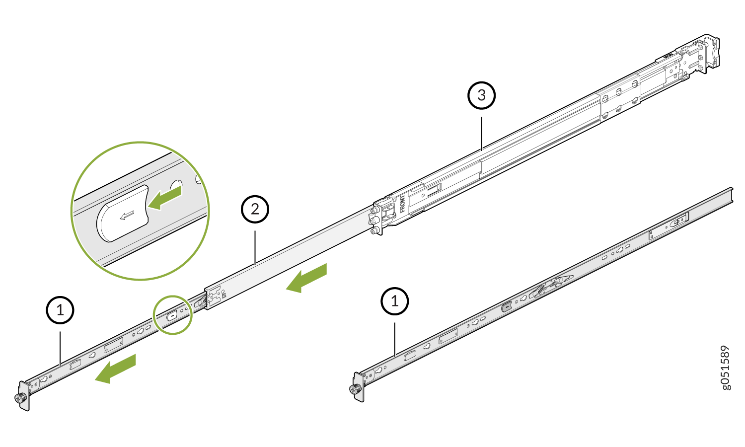
1—Inner rail bracket
2—Slider rail
3—Outer rail
Install the inner rail that you removed from the rail assembly on to the switch chassis using the M4 screws.
Press the latch on the slider rail down and retract the slider rail into the slide rail assembly.
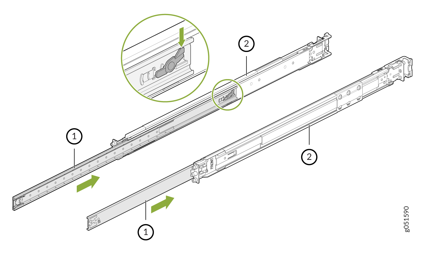
1—Slider rail
2—Outer rail
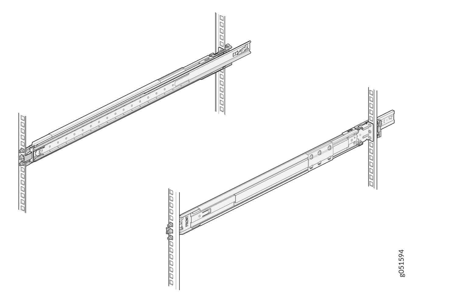
Install the Slider Rail and Outer Rail Assembly in the Rack
Move the latch on the rear end of the rail assembly to the open position.
Align the rear end of the outer rail with the rear rack-post holes that you want to use. The installation pegs on the outer rail enter the rack-post holes from the inside of the rack post.
Push the outer rail rear installation pegs into the rear rack-post holes. You will hear a click.
Move the latch to the close position. The rear bracket of the outer rail wraps around the outside of the rear rack post.
Note: The rear end of the outer rail assembly is fastened to the rear rack-post using M5x13.0L screws.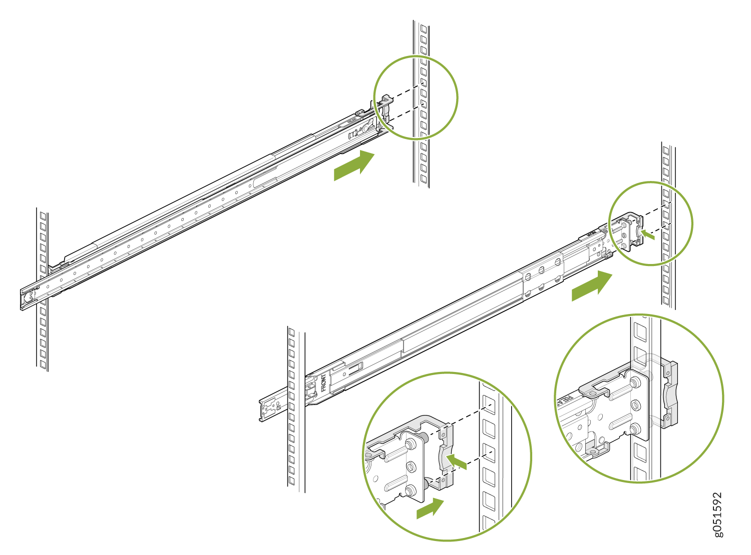
Adjust the slider rail length and push the front-mounting pegs on it into the front rack-post holes. You will hear a click.
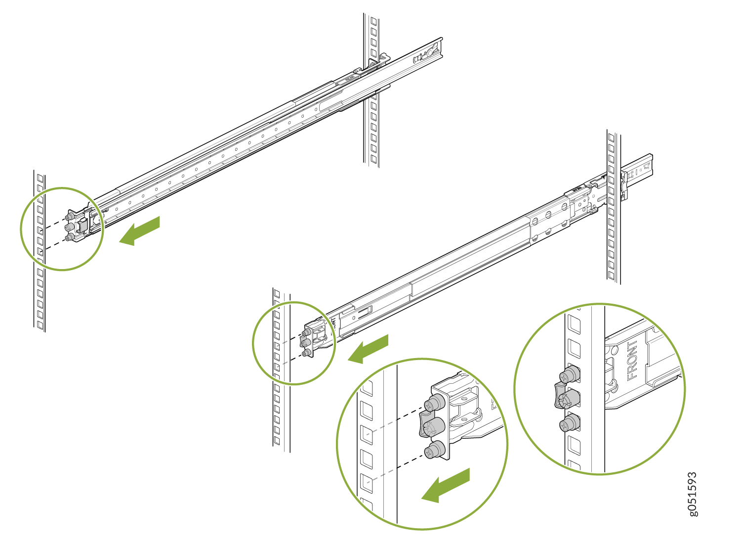
The slide rail assembly is fully installed. Verify that both the slide rail assemblies are at the same height on the rack posts and are level front-to-back.
Mount the Switch in the Rack
Pull the slider rails out to their full extended lock position. Ensure that the ball bearing retainer is located at the front of the slider rail.
Attach the inner rail brackets to the chassis. Align the keyholes of the brackets over the shoulder screws of the chassis and slide the brackets toward the rear of the chassis.
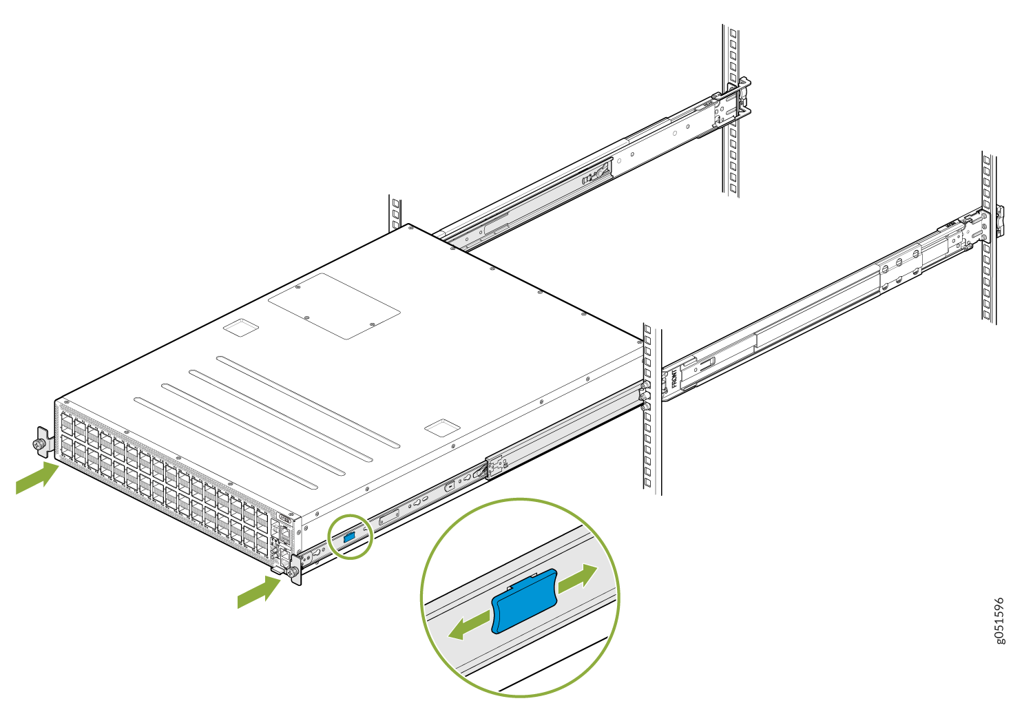
Lift the switch and align the rear of the inner rail brackets with the front ends of the slider rails on the rack.
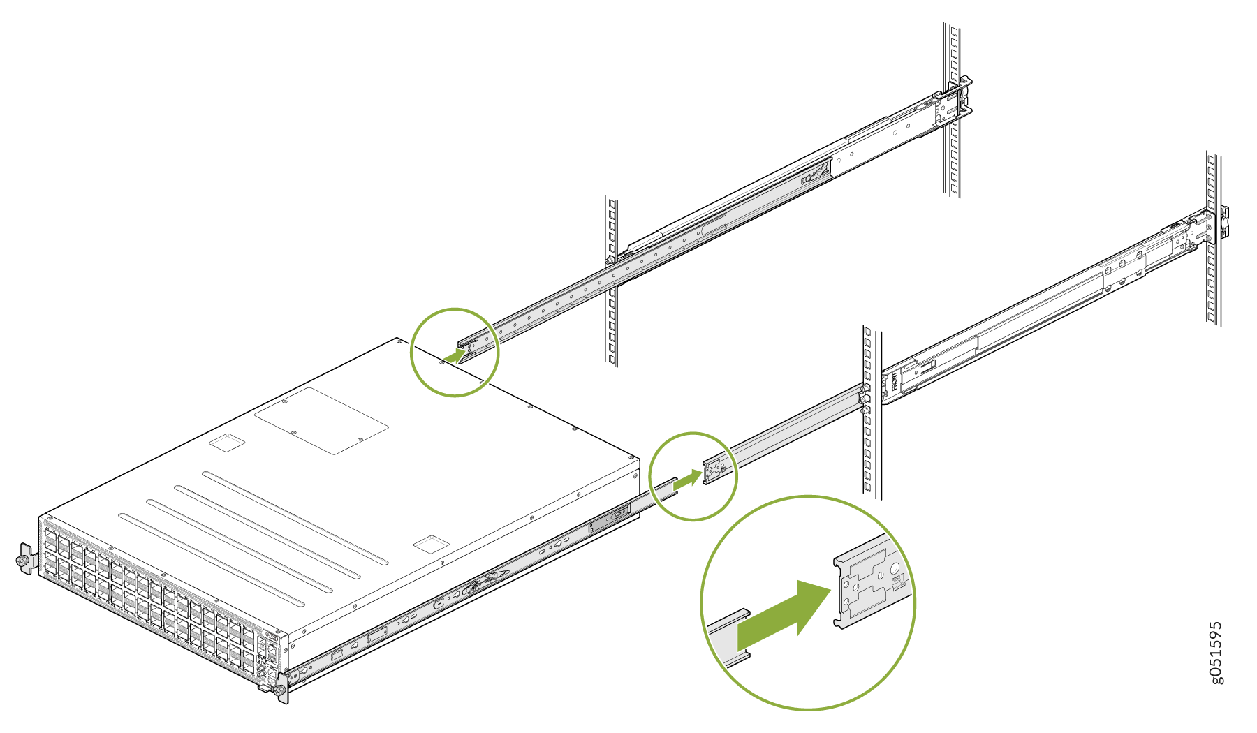
Press the blue release tab on the inner rail brackets. Slide the inner rail brackets holding the switch into the slider rail until you hit a stop.
Tighten the two thumbscrews to secure the switch.
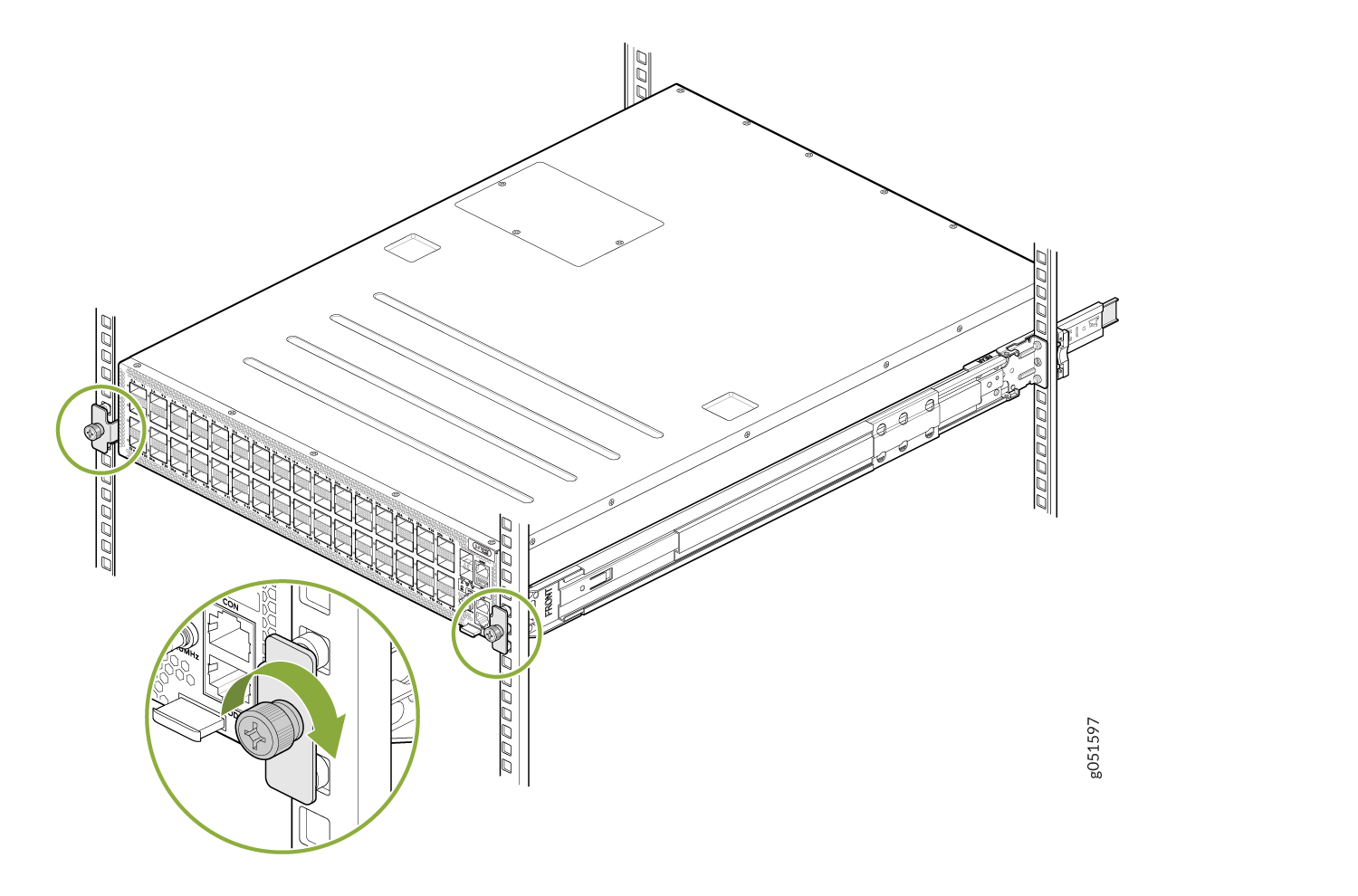
The switch is now mounted in the rack.
Connect the QFX5241-64OD and QFX5241-64QD Switches to Power
- Ground the QFX5241-64OD and QFX5241-64QD Switches
- Connect AC Power to QFX5241-64OD and QFX5241-64QD Switches
- Connect DC Power to QFX5241-64OD and QFX5241-64QD Switches
Ground the QFX5241-64OD and QFX5241-64QD Switches
You must connect QFX5241-64OD and QFX5241-64QD switches to earth ground before you connect it to power. Grounding the switches helps to:
-
Ensure proper operation
-
Meet safety and EMI requirements
To ground the QFX5241-64OD and QFX5241-64QD switches:
-
Secure the grounding lug to the protective earthing
terminal with the M6 screws and star washers.
Figure 1: Connect a Grounding Cable to the QFX5241-64OD and QFX5241-64QD Switches
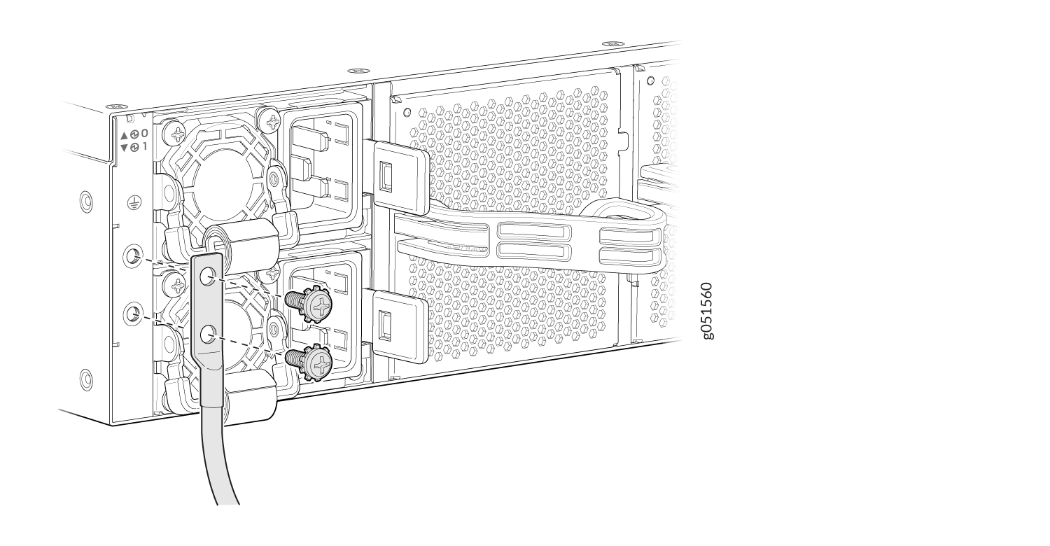
To gain additional grounding for the chassis of your QFX5241-64OD and QFX5241-64QD switches, connect the PSU in the switch into a grounded power outlet. Use a power cord appropriate for your geographical location.
Connect AC Power to QFX5241-64OD and QFX5241-64QD Switches
Ensure that you have a power cord appropriate for your geographical location available to connect AC power to the switch.
Before you begin connecting AC power to the switch:
-
Ensure that you have taken the necessary precautions to prevent electrostatic discharge (ESD) damage.
-
Ensure that you have connected the switch chassis to earth ground. See Ground the QFX5241-64OD and QFX5241-64QD Switches.
-
Install the PSUs in the chassis. For instructions on installing the PSU in the QFX5241-64OD and QFX5241-64QD switches, see Install an AC Power Supply Unit in QFX5241 Switches.
For detailed instructions, see Connect the QFX5241-64OD and QFX5241-64QD Switches to Power.
To connect AC power to the QFX5241-64OD and QFX5241-64QD switches:
-
Locate the power cords shipped with the switch; the cords have plugs
appropriate for your geographical location. See AC Power Cord Specifications.
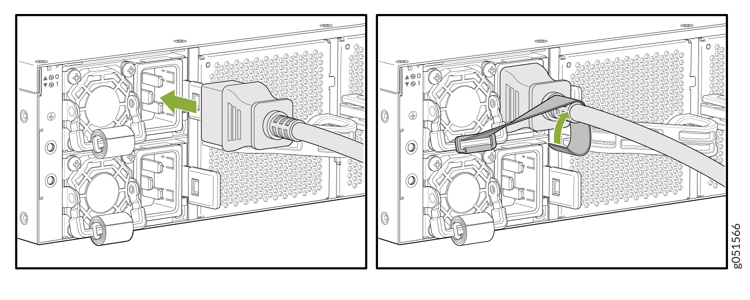
For each PSU:
-
Fasten the power cord using the strap provided on the PSU. See
Figure 2.
Figure 2: Connect the AC Power Cord
-
Fasten the power cord using the strap provided on the PSU. See
Figure 2.
Connect DC Power to QFX5241-64OD and QFX5241-64QD Switches
Ensure that you have a power cord appropriate for your geographical location available to connect DC power to the switch.
Before you begin connecting DC power to the switch:
-
Ensure that you have taken the necessary precautions to prevent electrostatic discharge (ESD) damage.
-
Ensure that you have connected the switch chassis to earth ground. See Ground the QFX5241-64OD and QFX5241-64QD Switches.
-
Install the PSUs in the chassis. For instructions on installing a DC PSU in the QFX5241-64OD and QFX5241-64QD switches, see Install a Power Supply Unit in QFX5241-64OD and QFX5241-64QD Switches.
For detailed instructions, see Connect DC Power to QFX5241-64OD and QFX5241-64QD Switches.
To connect DC power to the QFX5241-64OD and QFX5241-64QD switches:
-
Locate the power cords shipped with the switch; the cords have plugs
appropriate for your geographical location. See DC Power Cord Specifications.
To connect each PSU to a power source:
-
Insert the power cord connector firmly into the DC inlet on the
PSU faceplate. See Figure 3.
Figure 3: Connect the DC Power Cord
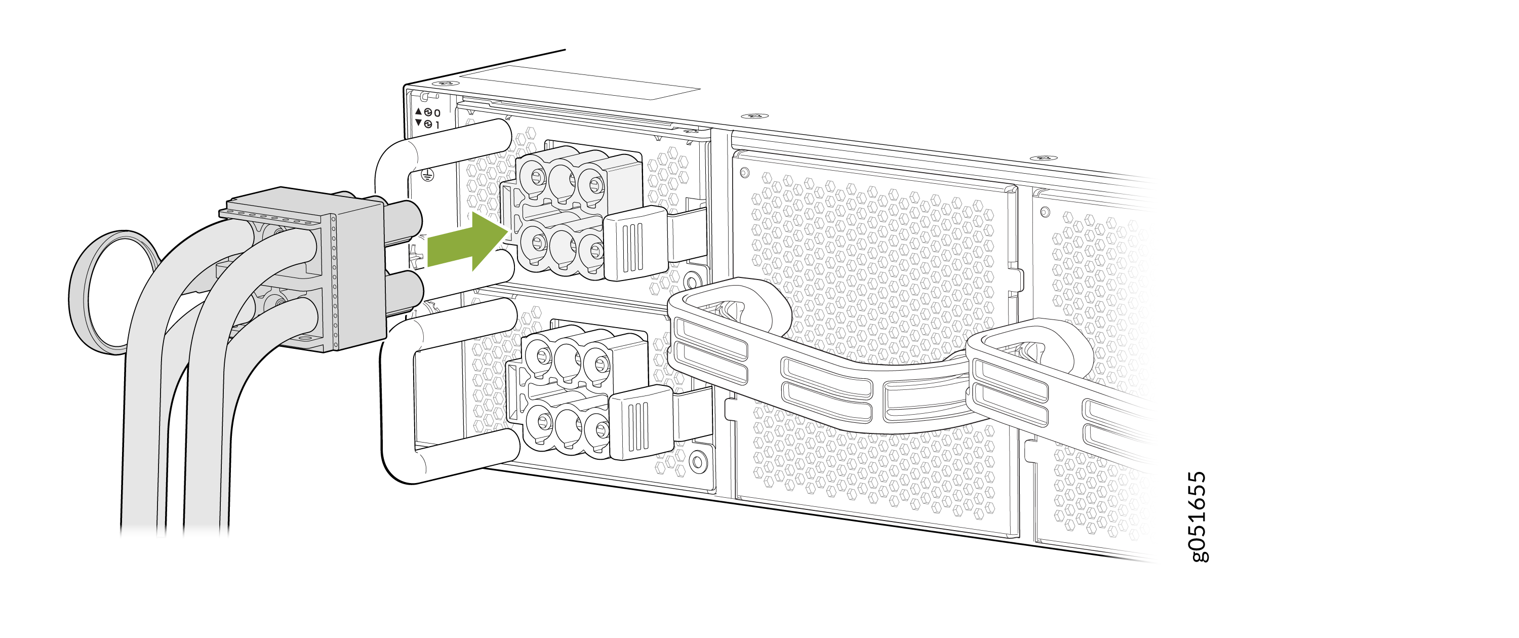
The latch on the power cord connector locks into the corresponding slot on the PSU faceplate.
-
Insert the power cord connector firmly into the DC inlet on the
PSU faceplate. See Figure 3.