Connect the QFX5241-64OD and QFX5241-64QD Switches to Power
Ground the QFX5241-64OD and QFX5241-64QD Switches
You must connect QFX5241-64OD and QFX5241-64QD switches to earth ground before you connect it to power. Grounding helps your switch meet safety and EMI requirements and ensures proper switch functioning (or operation).
You must install QFX5241-64OD and QFX5241-64QD switches in a restricted-access location and ensure that the chassis is always properly grounded. QFX5241-64OD and QFX5241-64QD switches come with a two-hole protective grounding terminal provided on the chassis. See Figure 1. Under all circumstances, use this grounding connection to ground the chassis. For AC-powered systems, you must also use the grounding wire in the AC power cord along with the two-hole grounding lug connection. The system is tested to meet or exceed all applicable EMC regulatory requirements for the two-hole protective grounding terminal.
Ensure that you have the following parts and tools available:
-
A grounding cable (not provided)—2 AWG, minimum 90° C wire, or as permitted by the local code.
-
A grounding lug (not provided)—Panduit LCDXN2-14AF-E or equivalent grounding lug. The grounding lug attaches to the device chassis through the left-front mounting bracket, providing a protective earthing terminal for the device.
-
Two M6 screws with star washers (not provided)
-
Phillips (+) screwdriver, number 2
-
ESD grounding strap (not provided)
To ground the QFX5241-64OD and QFX5241-64QD switches:
-
Secure the grounding lug to the protective earthing
terminal with the M6 screws and star washers.
Figure 1: Connect a Grounding Cable to the QFX5241-64OD and QFX5241-64QD AC Switches
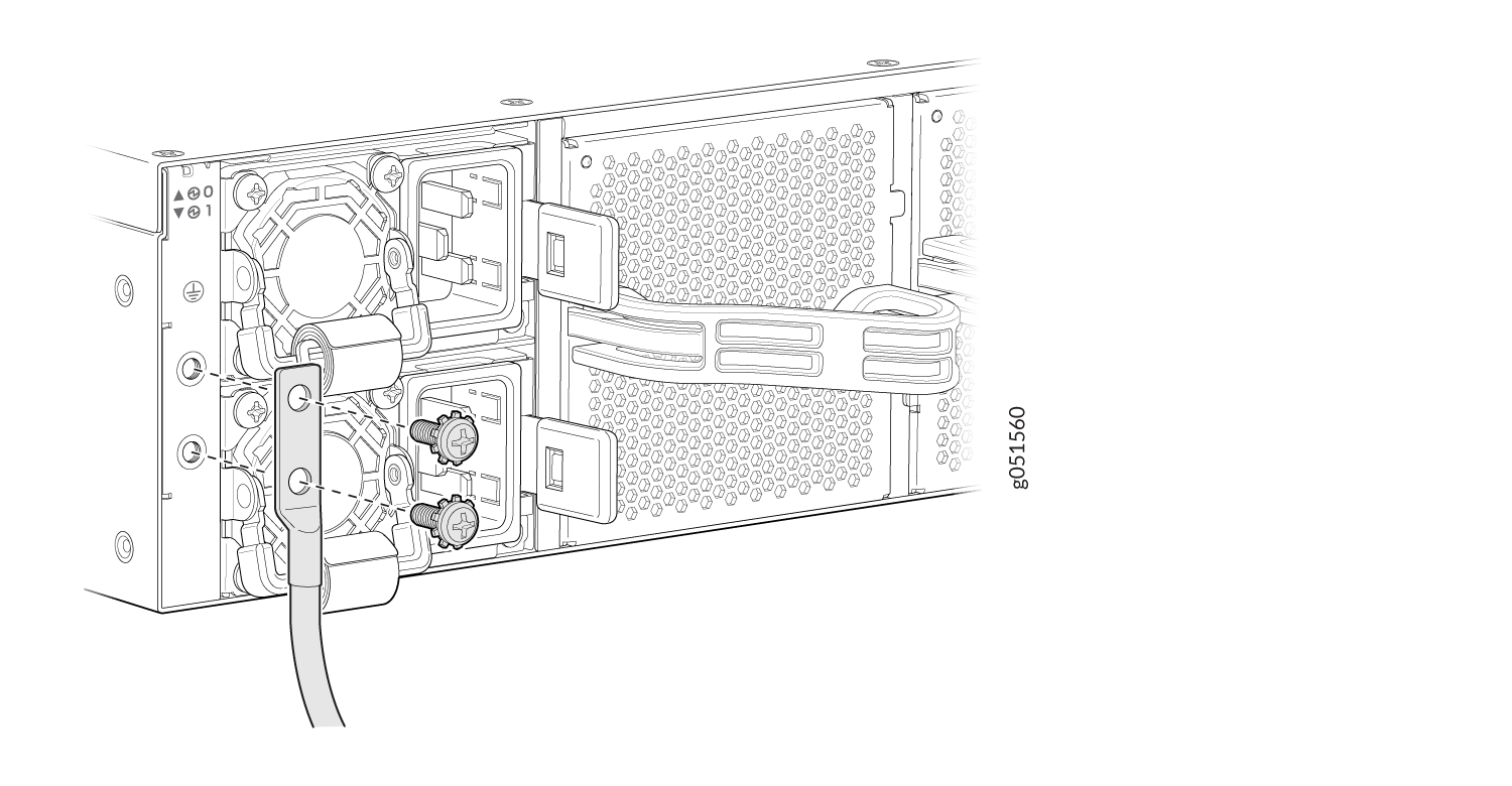 Figure 2: Connect a Grounding Cable to the QFX5241-64OD and QFX5241-64QD DC Switches
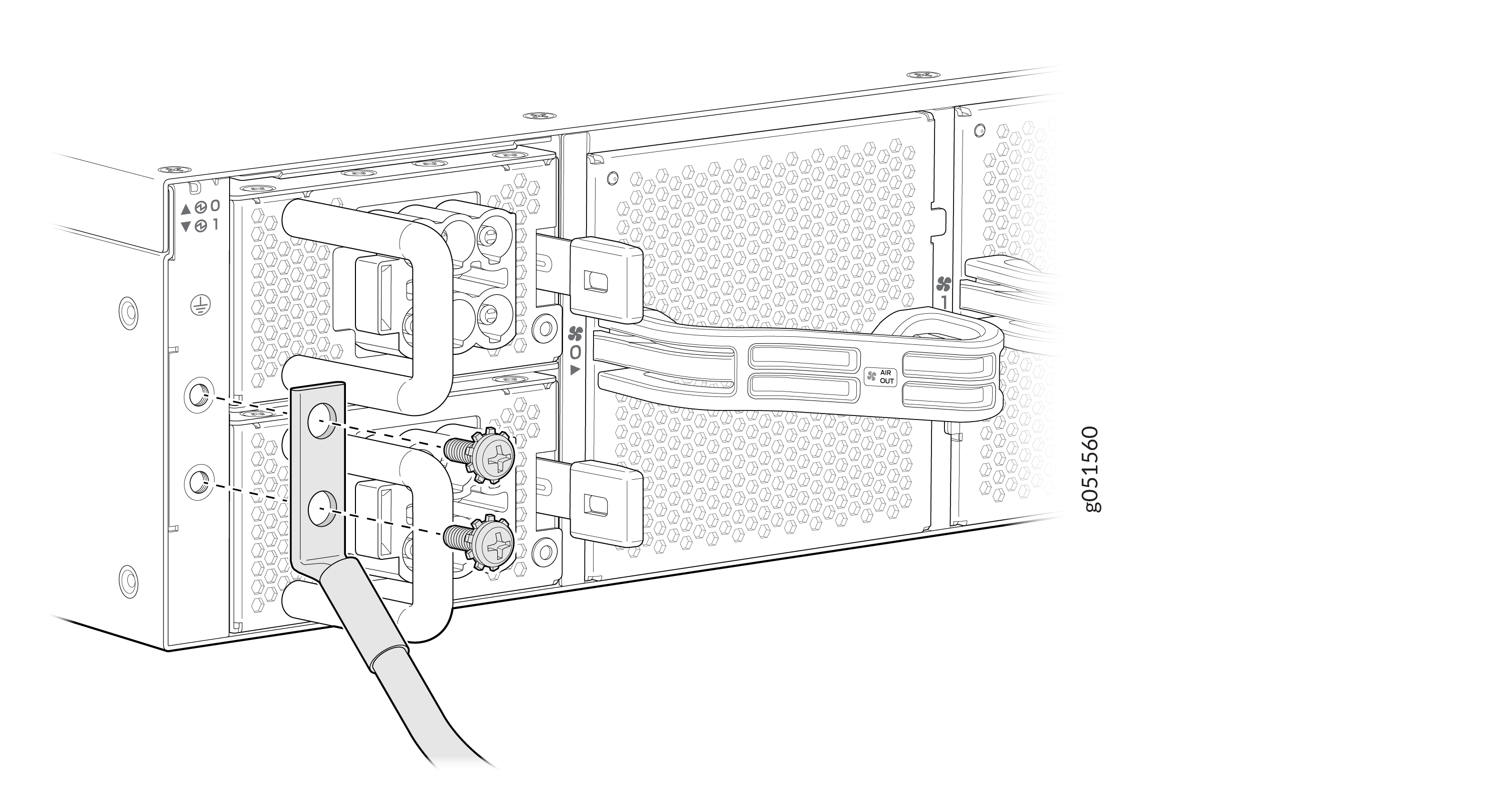
To gain additional grounding for the chassis of your QFX5241-64OD and QFX5241-64QD switches, connect the PSU in the switch into a grounded power outlet. Use a power cord appropriate for your geographical location.
Connect AC Power to QFX5241-64OD and QFX5241-64QD Switches
Ensure that you have a power cord appropriate for your geographical location available to connect AC power to the switch.
Before you begin connecting AC power to the switch:
-
Ensure that you have taken the necessary precautions to prevent electrostatic discharge (ESD) damage.
-
Ensure that you have connected the switch chassis to earth ground. See Ground the QFX5241-64OD and QFX5241-64QD Switches
CAUTION:Before you connect power to the switch, a licensed electrician must attach a cable lug to the grounding cables that you supply. A cable with an incorrectly attached lug can damage the switch (for example, by causing a short circuit).
To meet safety and electromagnetic interference (EMI) requirements and to ensure proper operation, you must connect the chassis to earth ground before you connect it to power. For installations that require a separate grounding conductor to the chassis, use the protective earthing terminal on the switch chassis to connect to the earth ground. For instructions on connecting earth ground, see Ground the QFX5241-64OD and QFX5241-64QD Switches. The switch gains additional grounding when you plug the PSU in the switch into a grounded power outlet by using the AC power cord appropriate for your geographical location.
-
Install the power supply units (PSUs) in the chassis. For instructions on installing the PSU in the QFX5241-64OD and QFX5241-64QD switches, see Install an AC Power Supply Unit in QFX5241 Switches.
Both the QFX5241-64OD and QFX5241-64QD switches ship from the factory with two preinstalled AC PSUs. The AC PSUs offer 1+1 redundancy. The PSUs are hot-removable and hot-insertable field-replaceable units (FRUs). You can replace a PSU in the slots adjacent to the fan modules without powering off the switch or disrupting its operation.
Each PSU must be connected to a dedicated power source outlet.
To connect AC power to the QFX5241-64OD and QFX5241-64QD switches:
-
Locate the power cords shipped with the switch; the cords have plugs
appropriate for your geographical location. See AC Power Cord Specifications.
For each PSU:
-
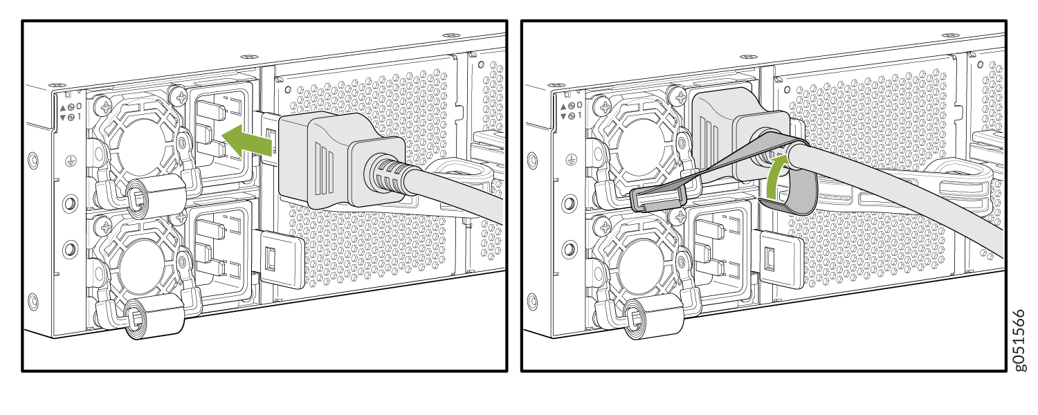
Fasten the power cord using the strap provided on the PSU. See
Figure 3.
Figure 3: Connect the AC Power Cord
-
Fasten the power cord using the strap provided on the PSU. See
Figure 3.
Connect DC Power to QFX5241-64OD and QFX5241-64QD Switches
Ensure that you have a power cord appropriate for your geographical location available to connect DC power to the switch.
Before you begin connecting DC power to the switch:
-
Ensure that you have taken the necessary precautions to prevent electrostatic discharge (ESD) damage.
-
Ensure that you have connected the switch chassis to earth ground. See Ground the QFX5241-64OD and QFX5241-64QD Switches.
CAUTION:Before you connect power to the switch, a licensed electrician must attach a cable lug to the grounding cable that you supply. A cable with an incorrectly attached lug can damage the switch (for example, by causing a short circuit).
To meet safety and electromagnetic interference (EMI) requirements and to ensure proper operation, you must connect the chassis to earth ground before you connect it to power. For installations that require a separate grounding conductor to the chassis, use the protective earthing terminal on the switch chassis to connect to the earth ground. For instructions on connecting earth ground, see Ground the QFX5241-64OD and QFX5241-64QD Switches. The switch gains additional grounding when you plug the PSU in the switch into a grounded power outlet by using the DC power cord appropriate for your geographical location.
-
Install the PSUs in the chassis. For instructions on installing DC PSUs in the QFX5241-64OD and QFX5241-64QD switches, see Install a Power Supply Unit in QFX5241-64OD and QFX5241-64QD Switches.
The QFX5241-64OD and QFX5241-64QD switches ship from the factory with two preinstalled DC PSUs. The DC PSUs offer 1+1 redundancy. One PSU powers the switch, while the other serves as a backup. If the primary PSU encounters an issue, the backup PSU powers the switch.
The PSUs are hot-removable and hot-insertable field-replaceable units (FRUs). You can replace a PSU in the slots adjacent to the fan modules without powering off the switch or disrupting its operation.
Each PSU must be connected to a dedicated power source outlet.
To connect DC power to the QFX5241-64OD and QFX5241-64QD switches:
-
Locate the power cords shipped with the switch; the cords have plugs
appropriate for your geographical location. See DC Power Cord Specifications.
To connect each PSU to a power source:
-
Insert the power cord connector firmly into the DC inlet on the PSU
faceplate. See Figure 4.
Figure 4: Connect the DC Power Cord
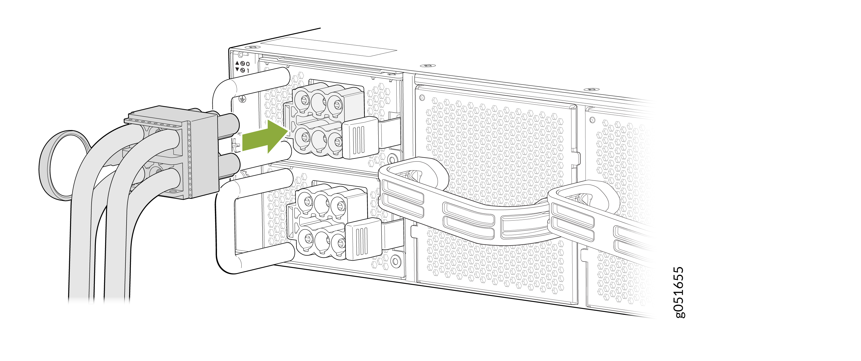
The latch on the power cord connector locks into the corresponding slot on the PSU faceplate.
-
Insert the power cord connector firmly into the DC inlet on the PSU
faceplate. See Figure 4.