ON THIS PAGE
QFX5241-64OD and QFX5241-64QD Power System
QFX5240-PWR-AC-AO—Two redundant AC power supply units (PSUs) power the AC variant of QFX5241-64OD and QFX5241-64QD switches (with 1 + 1 redundancy). Each QFX5240-PWR-AC-AO PSU provides a maximum output of 3000 W. The PSU modules support airflow out (AFO) cooling, also known as front-to-back or ports-to FRUs airflow. The PSUs are fully redundant and perform load sharing after you install and power on the second PSU. The AC PSUs are hot-removable and hot-insertable field-replaceable units (FRUs). That is, you can remove and replace the PSUs without powering off the switch or disrupting the functioning of the switch.
QFX5241-PWR-DC-AO—Two redundant DC PSUs power the DC variant of QFX5241-64OD and QFX5241-64QD switches (with 1 + 1 redundancy). Each QFX5241-PWR-DC-AO PSU provides a maximum output power of 3000 W. The PSU modules support airflow out (AFO) cooling, also known as front-to-back or ports-to FRUs airflow. The PSUs are fully redundant and perform load sharing after you install and power on the second PSU. The DC PSUs are hot-removable and hot-insertable field-replaceable units (FRUs). That is, you can remove and replace the PSUs without powering off the switch or disrupting the functioning of the switch.
The typical power consumption of the QFX5241-64OD switch is 613 W and the maximum power consumption is 2198 W. The typical power consumption of the QFX5241-64QD switch is 616 W and the maximum power consumption is 2258 W.
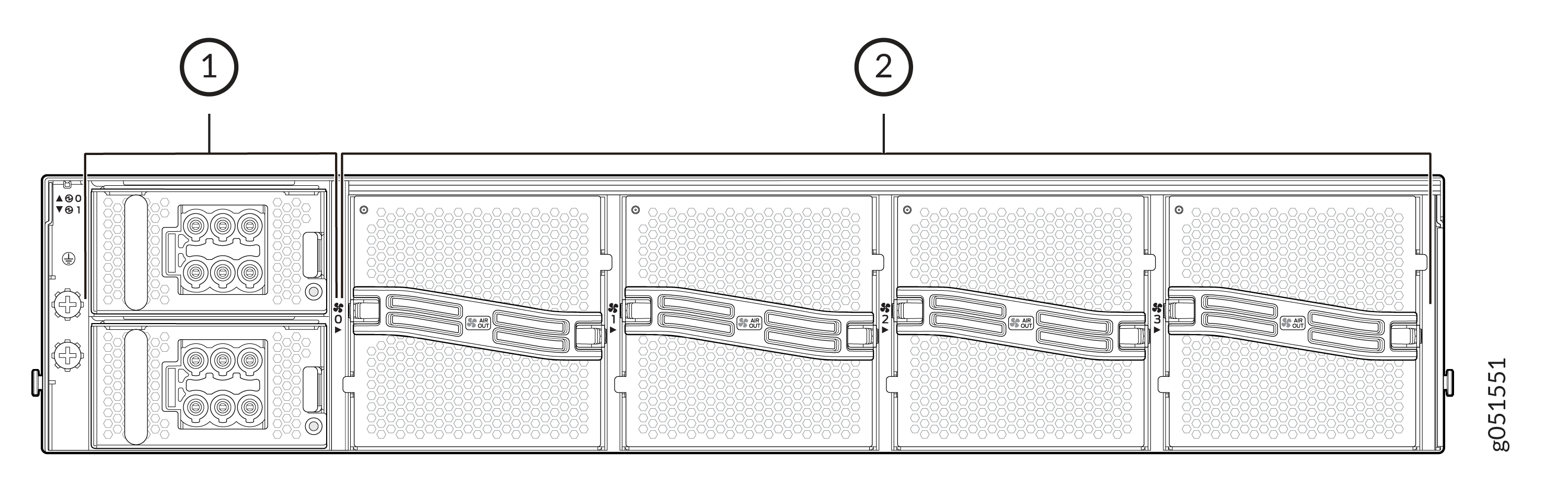
The PSUs for the QFX5241-64OD and QFX5241-64QD switches are located in the FRU panel at the rear of the chassis.
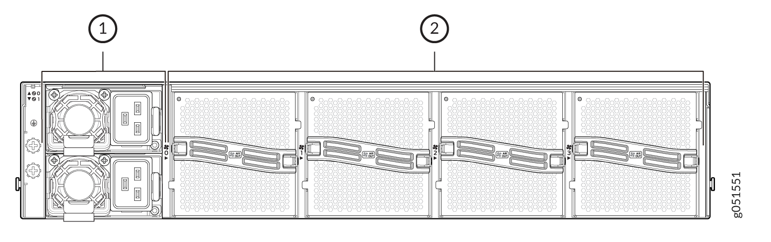
1 — Power supply units (PSUs) | 2 — Fan modules |
System Electrical Ratings for QFX5241-64OD and QFX5241-64QD Switches
Apart from the individual AC PSU and DC PSU electrical ratings, the QFX5241-64OD and QFX5241-64QD switch models are validated for a specific set of electrical ratings. The models of the QFX5250 switch are rated as follows:
QFX5241-64OD-AO and QFX5241-64QD-AO—The QFX5241-64OD and QFX5241-64QD AC model is rated for an input current of 16 A within an input voltage range of 200 through 240 volts AC (VAC) for each power supply operating within an AC input line frequency of 50 Hz through 60 Hz.
QFX5241-64OD-DO and QFX5241-64QD-DO—The QFX5241-32OD DC model is rated for an input current of 80 A within an input voltage range of -48 volts through -60 volts DC (VDC) for each power supply.
QFX5241-64OD and QFX5241-64QD AC Power Supply Unit Description
Each 3000-W AC power supply unit (PSU) has a single AC input and provides 12.2 V of output voltage for an AC input current rating of 16 A. The maximum output power of the PSU is 2.8 kilowatt (kW) for the input voltage range of 200 VAC through 215 VAC and 3 kW for the input voltage range of 215 VAC through 240 VAC.
At the output power and input voltages provided, you can maintain the input current of the switch within the rated limits.
|
Item |
Specifications |
|---|---|
|
AC input voltage |
Input voltage range: 200 V through 240 V. |
|
AC input current rating |
16 A |
| Output voltage (DC) |
12.2 V |
|
Maximum power output |
3000 W (for input voltage of 215 VAC through 240 VAC) 2800 W (for input voltage of 200 VAC through 214 VAC) |
|
Maximum power consumption |
QFX5241-64OD—2198 W QFX5241-64QD—2258 W |
|
Typical power consumption |
QFX5241-64OD—613 W QFX5241-64QD—616 W |
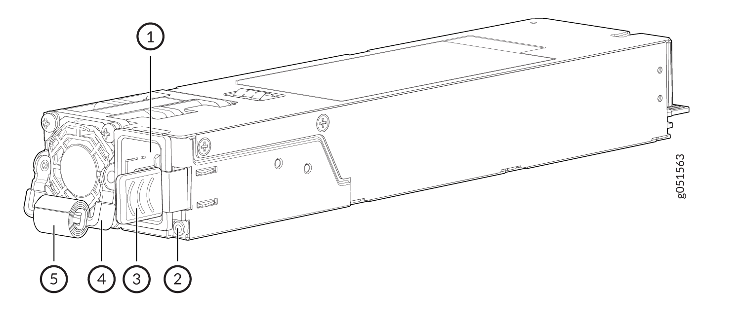
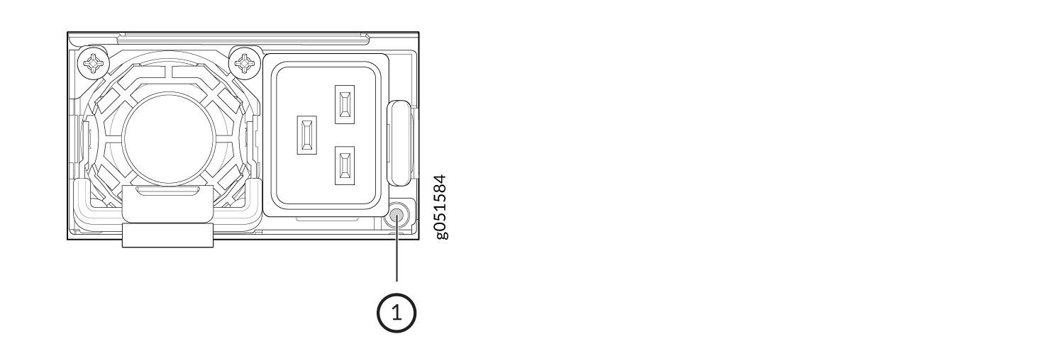
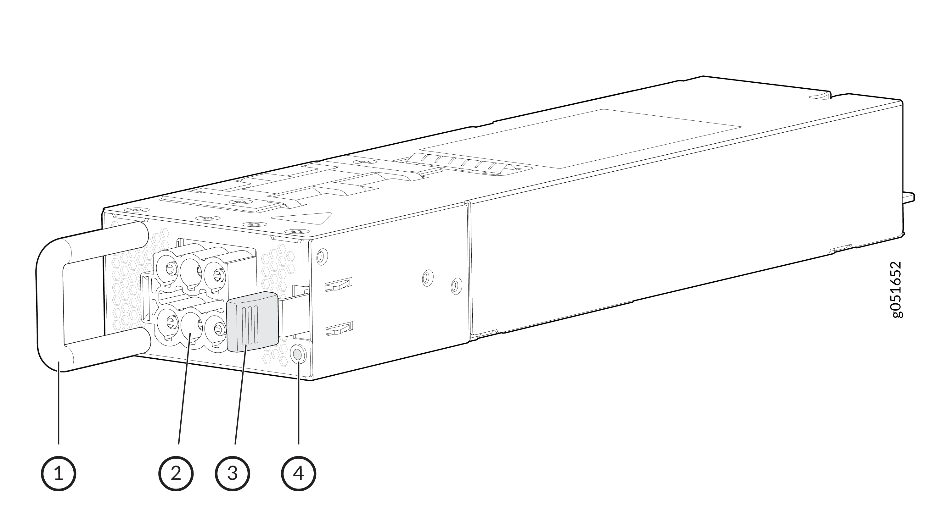
1 — Power connector | 4 — Handle |
2 — PSU LED | 5 — Velcro strap for cable management |
3 — Ejection lever |
To replace a PSU, see Maintain the QFX5241-64OD and QFX5241-64QD Power System.
AC Power Cord Specifications
We ship detachable AC power cords with the chassis.
In North America, AC power cords must not exceed 14.75 feet (approximately 4.5 meters) in length, to comply with National Electrical Code (NEC) Sections 400-8 (NFPA 75, 5-2.2) and 210-52, and Canadian Electrical Code (CEC) Section 4-010(3). The cords that can be ordered for the QFX Series switches are in compliance.
Table 2 lists AC power cord specifications provided.
|
Country/Region |
Electrical Specifications |
Plug Standards |
Juniper Model Number |
|---|---|---|---|
|
US/Europe |
250 VAC, 16 A |
Straight, C20 (EN 60320) to C19 (EN 60320)-, jumper cord |
CG_CBL-C19-C20-2M |
|
India |
250 VAC, 16 A |
Straight, C20 to C19, jumper cord |
CG_CBL-C19-C20-2M |
|
Other Countries (except US, Europe, and India) |
250 VAC, 16 A |
Straight, C20 to C19, jumper cord |
CG_CBL-C19-C20-2M |
QFX5241-64OD and QFX5241-64QD AC Power Supply Unit LED
Each QFX5241-64OD and QFX5241-64QD switch PSU has a single LED on the module faceplate to indicate the power status.
-
AC PSU LED
The AC PSU uses an amber and green bicolor LED to indicate the operating state.
|
LED Color and State |
Description |
|---|---|
|
Off |
The PSU is not receiving AC power. |
|
Solid green |
The PSU is on and functioning properly. |
|
Blinking green (1 second on, 1 second off, 0.5 Hz) |
The PSU is in standby state. |
|
Blinking green (0.25 second on, 0.25 second off, 2 Hz) |
The PSU is in redundant or offline mode. |
|
Solid amber |
Standby mode with overtemperature protection (OTP) The PSU shuts down because of a critical event such as high temperature, high power, high current, or fan failure. |
|
Any of the following faults detected at 12.2 V:
|
|
|
The PSU fan stops working for more than 15 seconds. |
QFX5241-64OD and QFX5241-64QD DC Power Supply Unit Description
The QFX5241-64OD and QFX5241-64QD DC power supply units (PSUs) are hot-removable and hot-insertable FRUs with redundancy (1 + 1). Each PSU has a single DC input and provides 12.2 V of output voltage to the system. The output power of the QFX5241-64OD and QFX5241-64QD DC PSU is 3 KW for the input voltage range of –48 V to –60 V.
|
Item |
Specifications |
|---|---|
|
DC input voltage |
Input voltage range: –48 V through –60 V. |
|
Output voltage (DC to DC) |
12.2 V |
|
Input current (for the maximum power output of 3 kW) |
80 A (maximum per PSU) |
|
Maximum power output |
3000 W |
-
Handle
-
Power connector
-
Ejection lever
-
PSU LED
DC Power Cord Specifications
We ship two detachable DC power cords (DC Power Cable) with the chassis. The DC power cords have 600 V rating, with 80 A per cord (40 A per pin), and 1.5 m of length. The DC power cords ship with the switch by default.
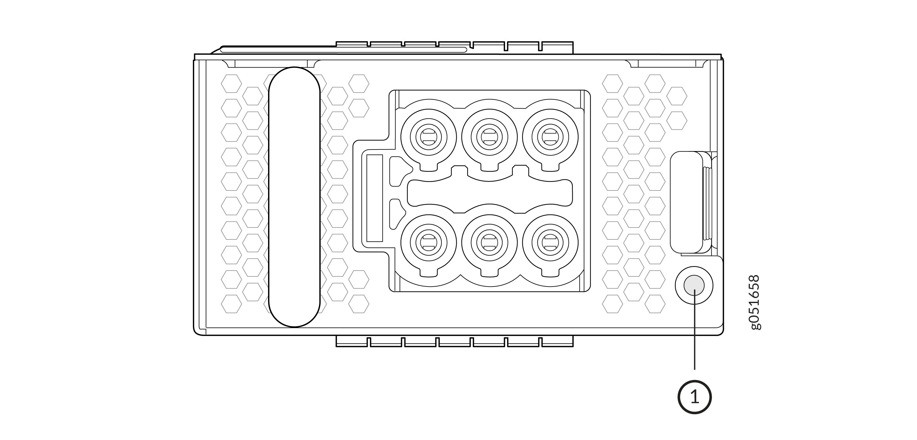
The DC power cord uses a six-wire DC power connector. This connector employs a six-pin female configuration that interfaces with DC power supply units (PSUs).
The connector pins are arranged in a 2×3 configuration (two rows of three pins). The six wires are organized into two bundles of three conductors each. One bundle (P1, P2, S1) carries negative polarity and negative sensing wire. The other bundle (S2, P3, P4) carries positive polarity and positive sensing wire. The P1, P2, and S1 wires are connected to the negative terminal of the DC source. The P3, P4, and S2 wires are connected to the positive terminal of the DC source. Depending on the installation method and power source configuration, the opposite end of the power cord terminates at the DC power source through ring terminal lugs, a mating connector, or another DC source as appropriate.
| 2x3-Pin Female Connector | Color | Wire | Description |
| P1 | 8 AWG (Blue) | W2 | Negative (-) bundle |
| P2 | 8 AWG (Brown) | W1 | Negative (-) bundle |
| S1 | 12 AWG (Black) | W3 | Negative (-) bundle (Sense Pin) |
| S2 | 12 AWG (Red) | W4 | Positive (+) bundle (Sense Pin) |
| P3 | 8 AWG (Green) | W6 | Positive (+) bundle |
| P4 | 8AWG (White) | W5 | Positive (+) bundle |
You must ensure that power connections maintain the proper polarity.
For field-wiring connections, use copper conductors only.
Make sure that DC power cables do not block access to the switch components or lie on the ground where people can trip on them.
QFX5241-64OD and QFX5241-64QD DC Power Supply Unit LED
Each QFX5241-64OD and QFX5241-64QD DC power supply unit (PSU) has a bicolor status LED on the PSU faceplate.
-
DC PSU LED
The DC PSU uses an amber and green bicolor LED to indicate the operating state.
|
LED Color and State |
Description |
|---|---|
|
Off |
The PSU is not receiving DC power. |
|
Solid green |
The PSU is on and functioning properly. |
|
Blinking green (1 second on, 1 second off, 0.5 Hz) |
The PSU is in standby state. |
|
Blinking green (0.25 second on, 0.25 second off, 2 Hz) |
The PSU is in redundant or offline mode. |
|
Yellow |
Standby mode with overtemperature protection (OTP) The PSU shuts down because of a critical event such as high temperature, high power, high current, or fan failure. |
|
Any of the following faults detected at 12.2 V:
|
|
|
The PSU fan stops working for more than 15 seconds. |