MX480 Chassis
MX480 Chassis Description
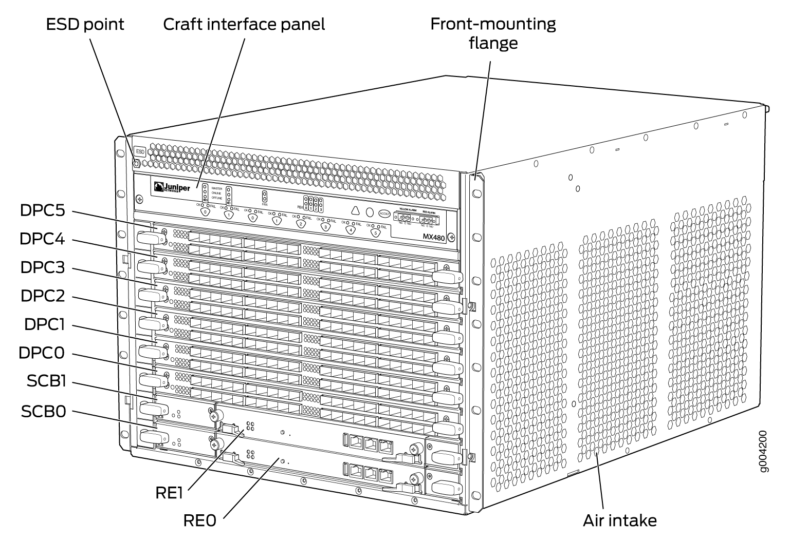
The router chassis is a rigid sheet metal structure that houses all the other router components (see Figure 1, Figure 2, and Figure 3). The chassis measures 14.0 in. (35.6 cm) high, 17.45 in. (44.3 cm) wide, and 24.5 in. (62.2 cm) deep (from the front to the rear of the chassis). The chassis installs in standard 800-mm (or larger) enclosed cabinets, 19-in. equipment racks, or telco open-frame racks. Up to five routers can be installed in one standard 48-U rack if the rack can handle their combined weight, which can be greater than 818 lb (371.0 kg).
See Also
MX480 Component Redundancy
A fully configured router is designed so that no single point of failure can cause the entire system to fail. Only a fully configured router provides complete redundancy. All other configurations provide partial redundancy. The following major hardware components are redundant:
Host subsystem—The host subsystem consists of a Routing Engine functioning together with an SCB. The router can have one or two host subsystems. If two host subsystems are installed, one functions as the primary and the other functions as the backup. If the primary host subsystem (or either of its components) fails, the backup can take over as the primary. To operate, each host subsystem requires a Routing Engine installed directly into in an SCB.
If the Routing Engines are configured for graceful switchover, the backup Routing Engine automatically synchronizes its configuration and state with the primary Routing Engine. Any update to the primary Routing Engine state is replicated on the backup Routing Engine. If the backup Routing Engine assumes primary role, packet forwarding continues through the router without interruption. For more information about graceful switchover, see the Junos OS Administration Library for Routing Devices.
Power supplies—In the low-line (110 V) AC power configuration, the router contains three or four AC power supplies, located horizontally at the rear of the chassis in slots PEM0 through PEM3 (left to right). Each AC power supply provides power to all components in the router. When three power supplies are present, they share power almost equally within a fully populated system. Four AC power supplies provide full power redundancy. If one power supply fails or is removed, the remaining power supplies instantly assume the entire electrical load without interruption. Three power supplies provide the maximum configuration with full power for as long as the router is operational.
In the high-line (220 V) AC power configuration, the router contains two or four AC power supplies located horizontally at the rear of the chassis in slots PEM0 through PEM3 (left to right). Each AC power supply provides power to all components in the router. When two or more power supplies are present, they share power almost equally within a fully populated system. Four AC power supplies provide full power redundancy. If one power supply fails or is removed, the remaining power supplies instantly assume the entire electrical load without interruption. Two power supplies provide the maximum configuration with full power for as long as the router is operational.
In the DC configuration, two power supplies are required to supply power to a fully configured router. One power supply supports approximately half of the components in the router, and the other power supply supports the remaining components. The addition of two power supplies provides full power redundancy. If one power supply fails or is removed, the remaining power supplies instantly assume the entire electrical load without interruption. Two power supplies provide the maximum configuration with full power for as long as the router is operational.
Cooling system—The cooling system has redundant components, which are controlled by the host subsystem. If one of the fans fails, the host subsystem increases the speed of the remaining fans to provide sufficient cooling for the router indefinitely.
MX480 Router Hardware and CLI Terminology Mapping
The MX480 router supports the components in Table 1.
Component |
Hardware Model Number |
CLI Name |
Description |
|---|---|---|---|
Chassis |
CHAS-BP-MX480 |
|
|
Craft Interface Panel |
CRAFT-MX480-S |
|
|
| Cooling System | |||
Fan tray |
FFANTRAY-MX480 |
|
|
High-capacity fan tray |
FFANTRAY-MX480-HC |
|
|
Filter kit |
FLTR-KIT-MX480 |
N/A |
|
| Host Subsystem | |||
Routing Engine |
|||
Switch Control Board |
SCB-MX |
|
|
SCBE-MX |
|
||
SCBE2-MX |
|
||
SCBE3-MX |
|
||
| Interface Modules | |||
DPC |
See DPCs Supported on MX240, MX480, and MX960 Routers in the MX Series Interface Module Reference. |
||
FPC |
MX-FPC2 |
|
|
MX-FPC3 |
|
||
MIC |
See MICs Supported by MX Series Routers in the MX Series Interface Module Reference. |
||
MPC |
See MPCs Supported by MX Series Routers in the MX Series Interface Module Reference. |
||
PIC |
See PICs Supported by MX240, MX480, and MX960 Routers in the MX Series Interface Module Reference. |
||
Interface module blank panel |
DPC-SCB-BLANK MIC-BLANK |
N/A |
|
Transceiver |
|
||
| Power System | |||
AC power supply |
PWR-MX480-AC |
|
|
PWR-MX480-1200-AC |
|
||
PWR-MX480-2520-AC (high-capacity) |
|
||
DC power supply |
PWR-MX480-DC |
|
|
PWR-MX480-1600-DC |
|
||
PWR-MX480-2400-DC |
|
||
Power supply blank panel |
PWR-BLANK-MX480 |
N/A |
|
See Also
MX480 Craft Interface Description
The craft interface allows you to view status and troubleshooting information at a glance and to perform many system control functions. It is hot-insertable and hot-removable. The craft interface is located on the front of the router above the card cage and contains LEDs for the router components, the alarm relay contacts, and alarm cutoff button. See Figure 4.
At least one SCB must be installed in the router for the craft interface to obtain power.
Alarm Relay Contacts on the MX480 Craft Interface
The craft interface has two alarm relay contacts for connecting the router to external alarm devices (see Figure 5). Whenever a system condition triggers either the red or yellow alarm on the craft interface, the alarm relay contacts are also activated. The alarm relay contacts are located on the upper right of the craft interface.
Alarm LEDs and Alarm Cutoff/Lamp Test Button on the MX480 Craft Interface
Two large alarm LEDs are located at the upper right of the craft interface. The circular red LED lights to indicate a critical condition that can result in a system shutdown. The triangular yellow LED lights to indicate a less severe condition that requires monitoring or maintenance. Both LEDs can be lit simultaneously.
A condition that causes an LED to light also activates the corresponding alarm relay contact on the craft interface.
To deactivate red and yellow alarms, press the button labeled ACO/LT (for “alarm cutoff/lamp test”), which is located to the right of the alarm LEDs. Deactivating an alarm turns off both LEDs and deactivates the device attached to the corresponding alarm relay contact on the craft interface.
Table 2 describes the alarm LEDs and alarm cutoff button in more detail.
Shape |
Color |
State |
Description |
|---|---|---|---|
 |
Red |
On steadily |
Critical alarm LED—Indicates a critical condition that can cause the router to stop functioning. Possible causes include component removal, failure, or overheating. |
 |
Yellow |
On steadily |
Warning alarm LED—Indicates a serious but nonfatal error condition, such as a maintenance alert or a significant increase in component temperature. |
 |
– |
– |
Alarm cutoff/lamp test button—Deactivates red and yellow alarms. Causes all LEDs on the craft interface to light (for testing) when pressed and held. |
MX480 Component LEDs on the Craft Interface
- Host Subsystem LEDs on the MX480 Craft Interface
- Power Supply LEDs on the MX480 Craft Interface
- DPC and MPC LEDs on the MX480 Craft Interface
- FPC LEDs on the MX480 Craft Interface
- SCB LEDs on the MX480 Craft Interface
- Fan LEDs on the MX480 Craft Interface
Host Subsystem LEDs on the MX480 Craft Interface
Each host subsystem has three LEDs, located on the upper left of the craft interface, that indicate its status. The LEDs labeled RE0 show the status of the Routing Engine in slot 0 and the SCB in slot 0. The LEDs labeled RE1 show the status of the Routing Engine and SCB in slot 1. Table 3 describes the functions of the host subsystem LEDs on the craft interface.
Label |
Color |
State |
Description |
|---|---|---|---|
MASTER |
Green |
On steadily |
Host is functioning as the primary. |
ONLINE |
Green |
On steadily |
Host is online and is functioning normally. |
OFFLINE |
Red |
On steadily |
Host is installed but the Routing Engine is offline. |
– |
Off |
Host is not installed. |
Power Supply LEDs on the MX480 Craft Interface
Each power supply has two LEDs on the craft interface that indicate its status. The LEDs, labeled 0 through 3, are located on the upper left of the craft interface next to the PEM label. Table 4 describes the functions of the power supply LEDs on the craft interface.
Label |
Color |
State |
Description |
|---|---|---|---|
PEM |
Green |
On steadily |
Power supply is functioning normally. |
Red |
On steadily |
Power supply has failed or power input has failed. |
DPC and MPC LEDs on the MX480 Craft Interface
Each DPC or MPC has LEDs on the craft interface that indicate its status. The LEDs, labeled 0 through 5, are located along the bottom of the craft interface. Table 5 describes the functions of the LEDs.
Label |
Color |
State |
Description |
|---|---|---|---|
OK |
Green |
On steadily |
Card is functioning normally. |
Blinking |
Card is transitioning online or offline. |
||
– |
Off |
The slot is not online. |
|
FAIL |
Red |
On steadily |
Card has failed. |
FPC LEDs on the MX480 Craft Interface
An FPC takes up two DPC slots when installed in an MX Series router. The LEDs, labeled 0 through 5, are located along the bottom of the craft interface. The LED corresponds to the lowest DPC slot number in which the FPC is installed. Table 6 describes the functions of the FPC LEDs.
Label |
Color |
State |
Description |
|---|---|---|---|
OK |
Green |
On steadily |
FPC is functioning normally. |
Blinking |
FPC is transitioning online or offline. |
||
– |
Off |
The slot is not online. |
|
FAIL |
Red |
On steadily |
FPC has failed. |
SCB LEDs on the MX480 Craft Interface
Each SCB has two LEDs on the craft interface that indicates its status. The SCB LEDs, labeled 0 and 1, are located along the bottom of the craft interface. Table 7 describes the functions of the SCB LEDs.
Label |
Color |
State |
Description |
|---|---|---|---|
OK |
Green |
On steadily |
SCB: Fabric and control board functioning normally. |
Blinking |
SCB is transitioning online or offline. |
||
– |
Off |
The slot is not online. |
|
FAIL |
Red |
On steadily |
SCB has failed. |
Fan LEDs on the MX480 Craft Interface
The fan LEDs are located on the top left of the craft interface. Table 8 describes the functions of the fan LEDs.
Label |
Color |
State |
Description |
|---|---|---|---|
FAN |
Green |
On steadily |
Fan is functioning normally. |
Red |
On steadily |
Fan has failed. |
MX480 Cable Management Brackets
The cable management brackets (see Figure 6 and Figure 7) consist of plastic dividers located on the left and right sides of each DPC, FPC, or MPC slot, and SCB slot. The cable management brackets allow you to route the cables outside the router and away from the DPCs, MPCs, MICs, PICs, and SCBs.