Maintaining MX480 Components
Routine Maintenance Procedures for the MX480 Router
Purpose
For optimum router performance, perform preventive maintenance procedures.
Action
Inspect the installation site for moisture, loose wires or cables, and excessive dust. Make sure that airflow is unobstructed around the router and into the air intake vents.
Check the status-reporting devices on the craft interface—System alarms and LEDs.
Inspect the air filter at the left rear of the router, replacing it every 6 months for optimum cooling system performance. Do not run the router for more than a few minutes without the air filter in place.
See Also
MX480 Field-Replaceable Units (FRUs)
Field-replaceable units (FRUs) are router components that can be replaced at the customer site. Replacing most FRUs requires minimal router downtime. The router uses the following types of FRUs:
Hot-removable and hot-insertable FRUs—You can remove and replace these components without powering off the router or disrupting the routing functions.
Hot-pluggable FRUs—You can remove and replace these components without powering off the router, but the routing functions of the system are interrupted when the component is removed.
Table 1 lists the FRUs for the MX960 router. Before you replace an SCB or a Routing Engine, you must take the host subsystem offline.
Hot-Removable and Hot-Insertable FRUs |
Hot-Pluggable FRUs |
|---|---|
|
|
See Also
Tools and Parts Required to Replace MX480 Hardware Components
To replace hardware components, you need the tools and parts listed in Table 2.
Tool or Part |
Components |
|---|---|
2.5-mm flat-blade (–) screwdriver |
|
7/16-in. (11 mm) nut driver or socket wrench |
|
Blank panels (if component is not reinstalled) |
|
Electrostatic bag or antistatic mat |
|
Electrostatic discharge (ESD) grounding wrist strap |
|
Flat-blade (–) screwdriver |
|
Phillips (+) screwdrivers, numbers 1 and 2 |
|
Rubber safety cap |
|
Wire cutters |
|
See Also
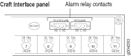
Replacing the MX480 Craft Interface
- Disconnecting the Alarm Relay Wires from the MX480 Craft Interface
- Removing the MX480 Craft Interface
- Installing the MX480 Craft Interface
- Connecting the Alarm Relay Wires to the MX480 Craft Interface
Disconnecting the Alarm Relay Wires from the MX480 Craft Interface
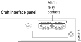
To disconnect the alarm relay wires from the router and an alarm-reporting device (see Figure 1):
- Disconnect the existing wire at the external device.
- Attach an ESD grounding strap to your bare wrist, and connect the other end of the strap to an ESD grounding point.
- Using a 2.5-mm flat-blade screwdriver, loosen the small screws on the face of the terminal block and remove the block from the relay contact.
- Using the 2.5-mm flat-blade screwdriver, loosen the small screws on the side of the terminal block. Remove existing wires from the slots in the front of the block.
See Also
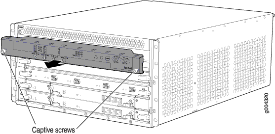
Removing the MX480 Craft Interface
To remove the craft interface (see Figure 2):
- Attach an ESD grounding strap to your bare wrist, and connect the other end of the strap to an ESD grounding point.
- Detach any external devices connected to the craft interface.
- Loosen the captive screws at the left and right corners of the craft interface faceplate.
- Grasp the craft interface faceplate and carefully tilt it toward you until it is horizontal.
- Disconnect the ribbon cable from the back of the faceplate by gently pressing on both sides of the latch with your thumb and forefinger. Remove the craft interface from the chassis.
See Also
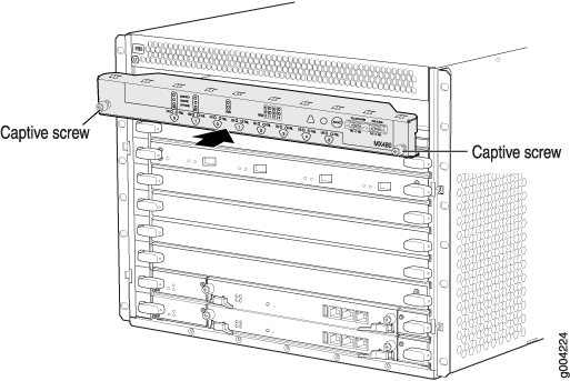
Installing the MX480 Craft Interface
To install the craft interface (see Figure 3):
- Attach an ESD grounding strap to your bare wrist, and connect the other end of the strap to an ESD grounding point.
- Grasp the craft interface with one hand, and hold the bottom edge of the craft interface with the other hand to support its weight.
- Orient the ribbon cable so that it plugs into the connector socket. The connector is keyed and can be inserted only one way.
- Align the bottom of the craft interface with the sheet metal above the card cage and press it into place.
- Tighten the screws on the left and right corners of the craft interface faceplate.
- Reattach any external devices connected to the craft interface.
Connecting the Alarm Relay Wires to the MX480 Craft Interface
To connect the alarm relay wires between a router and an alarm-reporting device (see Figure 4):
- Prepare the required length of replacement wire with gauge between 28-AWG and 14-AWG (0.08 and 2.08 mm2).
- Insert the replacement wires into the slots in the front of the block. Use a 2.5-mm flat-blade screwdriver to tighten the screws and secure the wire.
- Attach an ESD grounding strap to your bare wrist, and connect the other end of the strap to an ESD grounding point.
- Plug the terminal block into the relay contact, and use a 2.5-mm flat-blade screwdriver to tighten the screws on the face of the block.
- Attach the other end of the wires to the external device.
Replacing the MX480 Cable Management Brackets
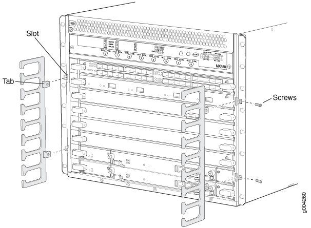
To remove the cable management brackets (see Figure 5):
- Attach an ESD grounding strap to your bare wrist, and connect the other end of the strap to an ESD grounding point.
- Loosen the captive screws on either side of the chassis.
- Remove the cable management brackets.
To install the cable management brackets (see Figure 5):
Attach an ESD grounding strap to your bare wrist, and connect the other end of the strap to an ESD grounding point.
Position the on the front sides of the chassis.
Insert the tabs into the slots.
Tighten the screws completely.
Replacing the Management Ethernet Cable on an MX Series Router
To replace the cable connected to the ETHERNET port:
- Attach an ESD grounding strap to your bare wrist, and connect the other end of the strap to an ESD grounding point.
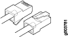
- Press the tab on the connector, and pull the connector straight out of the port. Figure 6 shows the connector.
- Disconnect the cable from the network device.
- Plug one end of the replacement cable into the ETHERNET port. Figure 7 shows the port.
- Plug the other end of the cable into the network device.

See Also
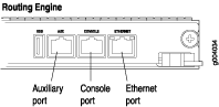
Replacing the Console or Auxiliary Cable on an MX480 Router
To use a system console to configure and manage the Routing Engine, connect it to the CONSOLE port on the Routing Engine. To use a laptop, modem, or other auxiliary device, connect it to the AUX port on the Routing Engine. Both ports accept a cable with an RJ-45 connector. If you want to connect a device to both ports, you must supply two separate cables.
We no longer include the RJ-45 console cable with the DB-9 adapter as part of the device package. If the console cable and adapter are not included in your device package, or if you need a different type of adapter, you can order the following separately:
-
RJ-45 to DB-9 adapter (JNP-CBL-RJ45-DB9)
-
RJ-45 to USB-A adapter (JNP-CBL-RJ45-USBA)
-
RJ-45 to USB-C adapter (JNP-CBL-RJ45-USBC)
If you want to use RJ-45 to USB-A or RJ-45 to USB-C adapter you must have X64 (64-Bit) Virtual COM port (VCP) driver installed on your PC. See, https://ftdichip.com/drivers/vcp-drivers/ to download the driver.
To replace a cable connected to a management console or auxiliary device:
- Attach an ESD grounding strap to your bare wrist, and connect the other end of the strap to an ESD grounding point.
- Press the tab on the connector, and pull the connector straight out of the port.
- Disconnect the cable from the console or auxiliary device.
- Plug the RJ-45 end of the replacement serial cable into the CONSOLE or AUX port. Figure 8 shows the external device ports on the Routing Engine.
- Plug the female DB-9 end into the console or auxiliary device's serial port.