MX480 AC Power System
MX480 AC Power Supply Description
Each AC power supply weighs approximately 5.0 lb (2.3 kg) and consists of one AC appliance inlet, an AC input switch, a fan, and LEDs to monitor the status of the power supply. Figure 1 shows the power supply. For existing power supplies, each inlet requires a dedicated AC power feed and a dedicated 15 A (250 VAC) circuit breaker.
For high-capacity power supplies, each inlet requires a dedicated AC power feed and a dedicated 16.0 A @ 100 VAC or 16.0 A @ 200 VAC circuit breaker, or as required by local code.
The router is pluggable type A equipment installed in a restricted-access location. It has a separate protective earthing terminal (sized for UNC 1/4-20 ground lugs) provided on the chassis in addition to the grounding pin of the power supply cord. This separate protective earthing terminal must be permanently connected to earth.
You can mix the MX480 high-capacity and normal-capacity power supplies only during the PEM upgrade process. We do not recommend using this configuration in any other cases.
AC Power Supply Configurations
The MX480 high-capacity and normal-capacity power supplies each support either of the following AC power configurations:
-
In the low-line (110 V) AC power configuration, the MX480 router contains three or four AC power supplies (see Figure 1), located horizontally at the rear of the chassis in slots PEM0 through PEM3 (left to right). Each AC power supply provides power to all components in the router. When three power supplies are present, they share power almost equally within a fully populated system. Four AC power supplies provide full power redundancy. If one power supply fails or is removed, the remaining power supplies assume the entire electrical load without interruption. Three power supplies provide the maximum configuration with full power for as long as the router is operational. The low-line configuration requires three power supplies and the fourth power supply provides redundancy. With high-capacity power supplies, you must have a minimum of three power supplies installed in the router.
-
In the high-line (220 V) AC power configuration, the MX480 router contains two or four AC power supplies (see Figure 1), located horizontally at the rear of the chassis in slots PEM0 through PEM3 (left to right). In a high-line AC power configuration, each AC power supply provides power to all components in the router. When two or more power supplies are present, they share power almost equally within a fully populated system. Four AC power supplies provide full power redundancy. If one power supply fails or is removed, the remaining power supplies assume the entire electrical load without interruption. Two power supplies provide the maximum configuration with full power for as long as the router is operational. In the two-PEM high-line configuration, either slots PEM0 and PEM1 or slots PEM2 and PEM3 are used. The high-line configuration requires two power supplies, where two PEMs are needed to fully power the system, with the third and fourth providing redundancy.
-
All supplies should have the same feed setting.
-
Correct usage of the feed setting is required for all supplies in order to get the desired power inventory management.
-
Juniper Networks strongly recommends that you install Junos OS Release 8.4R2 or later before deploying the MX480 router into service.
-
The XFP cages and optics on the MX480 router are industry standard parts that have limited tactile feedback for insertion of optics and fiber. You need to insert the optics and fiber firmly until the latch is securely in place. [PR/98055]
-
Do not mix AC and DC power supplies on an MX480 router. Mixing of AC supplies and DC supplies may damage your chassis. [PR/233340]
MX480 AC Power Supply LEDs
Each AC power supply faceplate contains three LEDs that indicate the status of the power supply (see Table 1). The power supply status is also reflected in two LEDs on the craft interface. In addition, a power supply failure triggers the red alarm LED on the craft interface.
Label |
Color |
State |
Description |
|---|---|---|---|
AC OK |
Yellow |
Off |
AC power input voltage is below 78 VAC. |
Green |
On |
AC power input voltage is within 78–264 VAC. |
|
DC OK |
Green |
Off |
DC power outputs generated by the power supply are not within the normal operating ranges. |
On |
DC power outputs generated by the power supply are within the normal operating ranges. |
||
PS FAIL |
Red |
Off |
Power supply is functioning normally. |
On |
Power supply is not functioning normally and its output voltage is out of regulation limits. Check AC OK and DC OK LEDs for more information. |
AC Electrical Specifications for the MX480 Router
Table 2 lists the AC power supply electrical specifications; Table 3 lists the AC power system specifications.
Item |
Specification |
|---|---|
| Normal-Capacity Power Supplies | |
Maximum output power |
1027 W (low line) 1590 W (high line) |
AC input voltage |
Operating range: 100 – 240 VAC (nominal) |
AC input line frequency |
50 to 60 Hz (nominal) |
AC input current rating |
11.0 A @ 200 VAC or 14.5 A @ 110 VAC maximum |
Efficiency Note:
This value is at full load and nominal voltage. |
85% (low line and high line) |
| High-Capacity Power Supplies | |
Maximum output power |
1167 W (low line) 2050 W (high line) |
AC input voltage |
Operating range: 100 – 240 VAC (nominal) |
AC input line frequency |
50 to 60 Hz (nominal) |
AC input current rating |
16 A @ 110 VAC maximum 15.1 A @ 200 VAC maximum |
Efficiency Note:
This value is at full load and nominal voltage. |
84% (low line) 89% (high line) |
Item |
Normal Capacity–Low Line |
Normal-Capacity–High Line |
High-Capacity–Low Line |
High-Capacity–High Line |
|---|---|---|---|---|
Redundancy |
3+1 |
2+2 |
3+1 |
2+2 |
Output power (maximum) per power supply |
1027 W |
1590 W |
1167 W |
2050 W |
Output power (maximum) per system |
3081 W |
6400 W |
3501 W |
4100 W |
See Also
AC Power Circuit Breaker Requirements for the MX480 Router
Each AC power supply has a single AC appliance inlet located on the power supply that requires a dedicated AC power feed. We recommend that you use a customer site circuit breaker rated for 15 A (250 VAC) minimum for each AC power supply, or as required by local code. Doing so enables you to operate the router in any configuration without upgrading the power infrastructure.
AC Power Cord Specifications for the MX480 Router
Each AC power supply has a single AC appliance inlet located on the power supply that requires a dedicated AC power feed. Most sites distribute power through a main conduit that leads to frame-mounted power distribution panels, one of which can be located at the top of the rack that houses the router. An AC power cord connects each power supply to the power distribution panel.
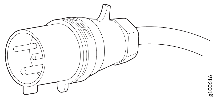
You can order detachable AC power cords, each approximately 8 ft (2.5 m) long that supply AC power to the router. The C19 appliance coupler end of the cord inserts into the AC appliance inlet coupler, type C20 (right angle) as described by International Electrotechnical Commission (IEC) standard 60320. The plug end of the power cord fits into the power source receptacle that is standard for your geographical location.
Table 4 provides specifications and AC Power Cord Specifications for the MX480 Router depicts the plug on the AC power cord provided for each country or region.
|
Country |
Model Number |
Electrical Specification |
Plug Type |
Graphic |
|---|---|---|---|---|
|
Australia |
CBL-M-PWR-RA-AU |
240 VAC, 50 Hz AC |
SAA/3/15 |
 |
|
China |
CBL-M-PWR-RA-CH |
220 VAC, 50 Hz AC |
IEC309 6h (pin and sleeve) 3-POLE |
 |
|
Europe (except Denmark, Italy, Switzerland, and United Kingdom) |
CBL-M-PWR-RA-EU |
220 or 230 VAC, 50 Hz AC |
CEE 7/7 |
 |
|
Italy |
CBL-M-PWR-RA-IT |
230 VAC, 50 Hz AC |
CEI 23-16/VII |
 |
|
Japan |
CBL-PWR-RA-JP15 |
125 VAC, 50 or 60 Hz AC |
JIS 8303 |
 |
|
CBL-M-PWR-RA-JP |
220 VAC, 50 or 60 Hz AC |
NEMA L6-20P |
 |
|
|
North America |
CBL-PWR-RA-US15 |
125 VAC, 60 Hz AC |
NEMA 5-15P |
 |
|
CBL-PWR-RA-TWLK-US15 |
125 VAC, 60 Hz AC |
NEMA L5-15P |
|
|
|
CBL-M-PWR-RA-US |
250 VAC, 60 Hz AC |
NEMA 6-20 |
 |
|
|
CBL-M-PWR-RA-TWLK-US |
250 VAC, 60 Hz AC |
NEMA L6-20P |
|
|
|
United Kingdom |
CBL-M-PWR-RA-UK |
240 VAC, 50 Hz AC |
BS89/13 |
 |
The AC power cord for the router is intended for use with the router only and not for any other use.

Translation from Japanese: The attached power cable is only for this product. Do not use the cable for another product.
In North America, AC power cords must not exceed 4.5 m (approximately 14.75 ft) in length, to comply with National Electrical Code (NEC) Sections 400-8 (NFPA 75, 5-2.2) and 210-52, and Canadian Electrical Code (CEC) Section 4-010(3). You can order AC power cords that are in compliance.
The router is pluggable type A equipment installed in a restricted-access location. It has a separate protective earthing terminal (sized for UNC 1/4-20 ground lugs) provided on the chassis in addition to the grounding pin of the power supply cord. This separate protective earthing terminal must be permanently connected to earth.
Power cords and cables must not block access to device components or drape where people could trip on them.