Help us improve your experience.

Let us know what you think.

Do you have time for a two-minute survey?


Connecting the MX480 to Power

Tools and Parts Required for MX480 Router Grounding and Power Connections

To ground and provide power to the router, you need the following tools and parts:

  • Phillips (+) screwdrivers, numbers 1 and 2

  • 2.5-mm flat-blade (–) screwdriver

  • 7/16-in. (11 mm) hexagonal-head external drive socket wrench, or nut driver, with a torque range between 23 lb-in. (2.6 Nm) and 25 lb-in. (2.8 Nm), for tightening nuts to terminal studs on each power supply on a DC-powered router.

  • Wire cutters

  • Electrostatic discharge (ESD) grounding wrist strap

CAUTION:

The maximum torque rating of the terminal studs on the DC power supply is 36 lb-in. (4.0 Nm). The terminal studs may be damaged if excessive torque is applied. Use only a torque-controlled driver or socket wrench to tighten nuts on the DC power supply terminal studs. Use an appropriately-sized driver or socket wrench, with a maximum torque capacity of 50 lb-in. or less. Ensure that the driver is undamaged and properly calibrated and that you have been trained in its use. You may wish to use a driver that is designed to prevent overtorque when the preset torque level is achieved.

Grounding the MX480 Router

You ground the router by connecting a grounding cable to earth ground and then attaching it to the chassis grounding points using UNC 1/4-20 two screws. You must provide the grounding cable (cable lugs are supplied with the router). To ground the router:

  1. Verify that a licensed electrician has attached the cable lug provided with the router to the grounding cable.
  2. Attach an ESD grounding strap to your bare wrist, and connect the other end of the strap to an approved site ESD grounding point. See the instructions for your site.
  3. Ensure that all grounding surfaces are clean and brought to a bright finish before grounding connections are made.
  4. Connect the grounding cable to a proper earth ground.
  5. Detach the ESD grounding strap from the site ESD grounding point.
  6. Attach an ESD grounding strap to your bare wrist, and connect the other end of the strap to an ESD grounding point.
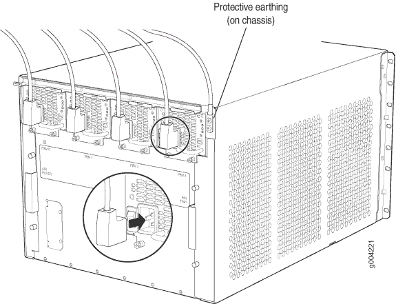
  7. Place the grounding cable lug over the grounding points on the upper rear of the chassis. The bolts are sized for UNC 1/4-20 bolts.
  8. Secure the grounding cable lug to the grounding points, first with the washers, then with the screws.
  9. Dress the grounding cable and verify that it does not touch or block access to router components, and that it does not drape where people could trip on it.

Connecting Power to an AC-Powered MX480 Router with Normal-Capacity Power Supplies

CAUTION:

Do not mix AC and DC power supply modules within the same device. Mixing currents can damage the device.

You connect AC power to the router by attaching power cords from the AC power sources to the AC appliance inlets located on the power supplies. For power cord and AC power specifications, see AC Power Cord Specifications for the MX480 Router.

To connect the AC power cords to the router (see Figure 1):

  1. Attach an ESD grounding strap to your bare wrist, and connect the other end of the strap to an ESD grounding point.
  2. Locate the power cords shipped with the router, which should have a plug appropriate for your geographical location (see AC Power Cord Specifications for the MX480 Router).
  3. Move the AC input switch next to the appliance inlet on the power supply to the off (O) position.
  4. Connect the power cord to the power supply.
  5. Insert the power cord plug into an external AC power source receptacle.
    Note:

    Each power supply must be connected to a dedicated AC power feed and a dedicated external circuit breaker.

  6. Route the power cord along the cable restraint toward the left or right corner of the chassis. If needed to hold the power cord in place, thread plastic cable ties, which you must provide, through the openings on the cable restraint.
  7. Verify that the power cord does not block the air exhaust and access to router components, or drape where people could trip on it.
  8. Repeat Step 2 through Step 6 for the remaining power supplies.
Figure 1: Connecting AC Power to the Router (110V)Connecting AC Power to the Router (110V)

Powering On an AC-Powered MX480 Router

To power on an AC-powered router:

  1. Attach an ESD grounding strap to your bare wrist, and connect the other end of the strap to an ESD grounding point.
  2. Verify that the power supplies are fully inserted in the chassis.
  3. Verify that each AC power cord is securely inserted into its appliance inlet.
  4. Verify that an external management device is connected to one of the Routing Engine ports (AUX, CONSOLE, or ETHERNET).
  5. Turn on the power to the external management device.
  6. Switch on the dedicated customer site circuit breakers for the power supplies. Follow the ESD and safety instructions for your site.
  7. Move the AC input switch on each power supply to the on (|) position and observe the status LEDs on each power supply faceplate. If an AC power supply is correctly installed and functioning normally, the AC OK and DC OK LEDs light steadily, and the PS Fail LED is not lit.

    If any of the status LEDs indicates that the power supply is not functioning normally, repeat the installation and cabling procedures.

    Note:

    After you power off a power supply, wait at least 60 seconds before you turn it back on. Likewise, after you power on a power supply, wait at least 60 seconds beforeyou turn it off.

    If the system is completely powered off when you power on the power supply, the Routing Engine (or RCB) boots as the power supply completes its startup sequence. If the Routing Engine finishes booting and you need to power off the system again, first issue the CLI request system halt command.

    After a power supply is powered on, it can take up to 60 seconds for status indicators—such as the status LEDs on the power supply and the show chassis command display—to indicate that the power supply is functioning normally. Ignore error indicators that appear during the first 60 seconds.

  8. On the external management device connected to the Routing Engine, monitor the startup process to verify that the system has booted properly.

Connecting Power to a DC-Powered MX480 Router with Normal Capacity Power Supplies

CAUTION:

Do not mix AC and DC power supply modules within the same device. Mixing currents can damage the device.

Warning:

Before you perform DC power procedures, ensure there is no power to the DC circuit. To ensure that all power is off, locate the circuit breaker on the panel board that services the DC circuit, switch the circuit breaker to the off position, and tape the switch handle of the circuit breaker in the off position.

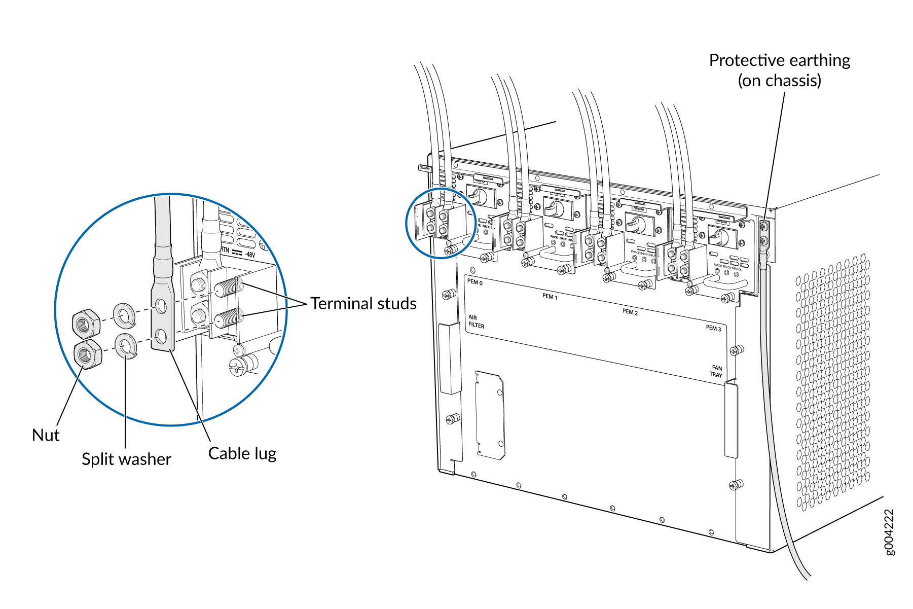
You connect DC power to the router by attaching power cables from the external DC power sources to the terminal studs on the power supply faceplates. You must provide the power cables (the cable lugs are supplied with the router).

To connect the DC source power cables to the router:

  1. Switch off the dedicated customer site circuit breakers. Ensure that the voltage across the DC power source cable leads is 0 V and that there is no chance that the cable leads might become active during installation.
  2. Attach an ESD grounding strap to your bare wrist, and connect the other end of the strap to an ESD grounding point.
  3. Move the DC circuit breaker on the power supply faceplate to the off (O) position.
  4. Remove the clear plastic cover protecting the terminal studs on the faceplate.
  5. Verify that the DC power cables are correctly labeled before making connections to the power supply. In a typical power distribution scheme where the return is connected to chassis ground at the battery plant, you can use a multimeter to verify the resistance of the –48V and RTN DC cables to chassis ground:
    • The cable with very large resistance (indicating an open circuit) to chassis ground is –48V.

    • The cable with very low resistance (indicating a closed circuit) to chassis ground is RTN.

    CAUTION:

    You must ensure that power connections maintain the proper polarity. The power source cables might be labeled (+) and (–) to indicate their polarity. There is no standard color coding for DC power cables. The color coding used by the external DC power source at your site determines the color coding for the leads on the power cables that attach to the terminal studs on each power supply.

  6. Install heat-shrink tubing insulation around the power cables.

    To install heat-shrink tubing:

    1. Slide the tubing over the portion of the cable where it is attached to the lug barrel. Ensure that tubing covers the end of the wire and the barrel of the lug attached to it.

    2. Shrink the tubing with a heat gun. Ensure that you heat all sides of the tubing evenly so that it shrinks around the cable tightly.

    Figure 1 shows the steps to install heat-shrink tubing.

    Note:

    Do not overheat the tubing.

    Figure 2: How to Install Heat-Shrink Tubing How to Install Heat-Shrink Tubing
  7. Remove the nut and washer from each of the terminal studs. (Use a 7/16-in. [11 mm] nut driver or socket wrench.)
  8. Secure each power cable lug to the terminal studs, first with the flat washer, then with the nut (see Connecting an MX480 DC Power Supply Cable). Apply between 23 lb-in. (2.6 Nm) and 25 lb-in. (2.8 Nm) of torque to each nut. Do not overtighten the nut. (Use a 7/16-in. [11 mm] torque-controlled driver or socket wrench.)
    1. Secure each positive (+) DC source power cable lug to the RTN (return) terminal.

    2. Secure each negative (–) DC source power cable lug to the –48V (input) terminal.

    CAUTION:

    Ensure that each power cable lug seats flush against the surface of the terminal block as you are tightening the nuts. Ensure that each nut is properly threaded onto the terminal stud. The nut should be able to spin freely with your fingers when it is first placed onto the terminal stud. Applying installation torque to the nut when improperly threaded may result in damage to the terminal stud.

    CAUTION:

    The maximum torque rating of the terminal studs on the DC power supply is 36 lb-in. (4.0 Nm). The terminal studs may be damaged if excessive torque is applied. Use only a torque-controlled driver or socket wrench to tighten nuts on the DC power supply terminal studs.

    The DC power supplies in slots PEM0 and PEM1 must be powered by dedicated power feeds derived from feed A, and the DC power supplies in slots PEM2 and PEM3 must be powered by dedicated power feeds derived from feed B. This configuration provides the commonly deployed A/B feed redundancy for the system.

  9. Route the power cables along the cable restraint toward the left or right corner of the chassis. If needed, thread plastic cable ties, which you must provide, through the openings on the cable restraint to hold the power cables in place.
  10. Replace the clear plastic cover over the terminal studs on the faceplate.
  11. Verify that the power cables are connected correctly, that they are not touching or blocking access to router components, and that they do not drape where people could trip on them.
  12. Repeat Steps 3 through 11 for the remaining power supplies.
Figure 3: Connecting Power Cables to the DC Power Supply Connecting Power Cables to the DC Power Supply

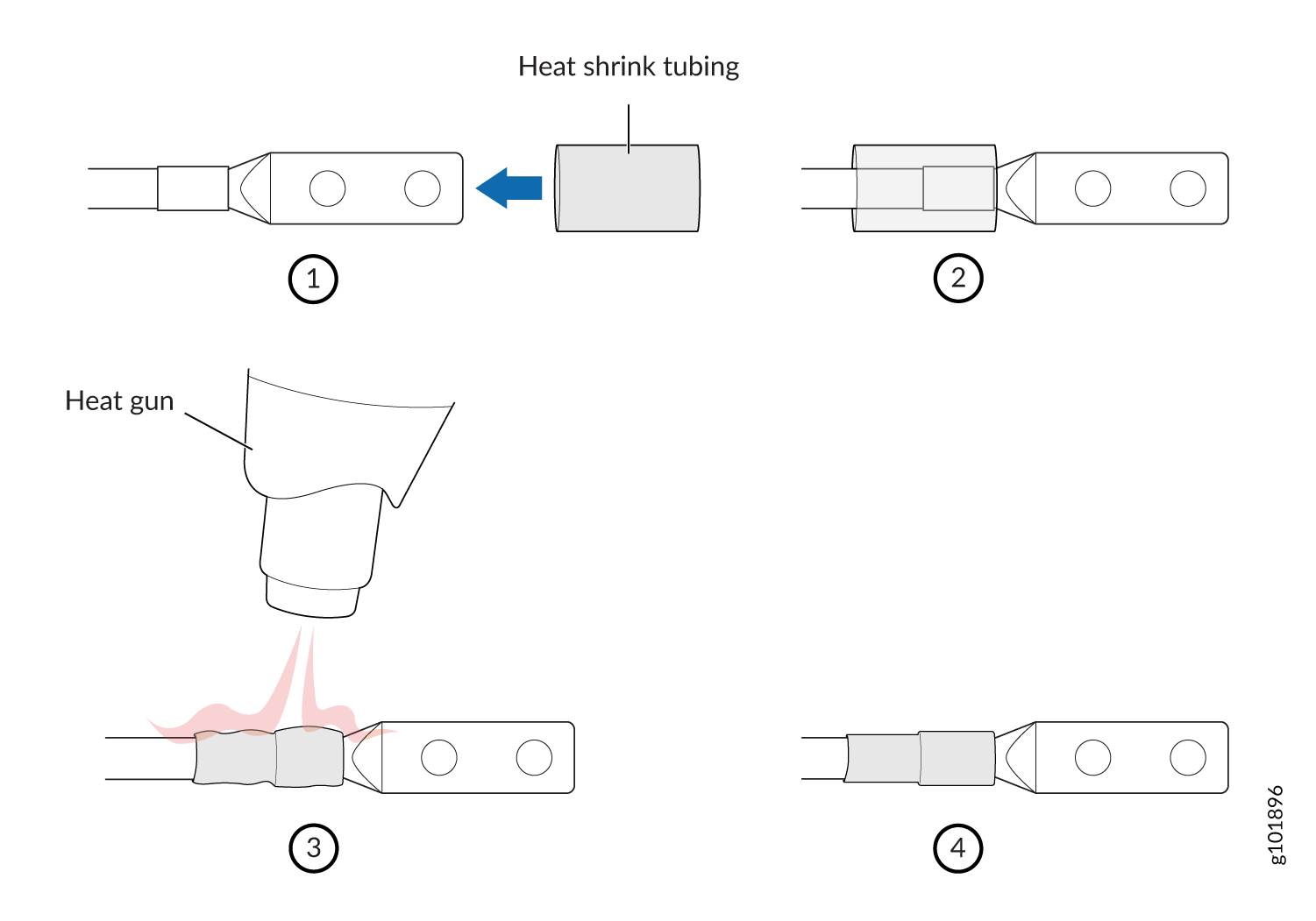
Powering On a DC-Powered MX480 Router with Normal Capacity Power Supplies

To power on a DC-powered router:

  1. Verify that an external management device is connected to one of the Routing Engine ports (CONSOLE, AUX, or ETHERNET).
  2. Turn on the power to the external management device.
  3. Attach an ESD grounding strap to your bare wrist, and connect the other end of the strap to an ESD grounding point.
  4. Verify that the power supplies are fully inserted in the chassis.
  5. Verify that the source power cables are connected to the appropriate terminal: the positive (+) source cable to the return terminal (labeled RETURN) and the negative (–) source cable to the input terminal (labeled -48V).
  6. Switch on the dedicated customer site circuit breakers to provide power to the DC power cables.
  7. Check the INPUT OK LED is lit steadily green to verify that power is present.
  8. If power is not present:
    • Verify that the fuse is installed correctly and turn on the breaker at the battery distribution fuse board or fuse bay.

    • Check the voltage with a meter at the terminals of the power supply for correct voltage level and polarity.

  9. On each of the DC power supplies, switch the DC circuit breaker to the center position before moving it to the on () position.
    Note:

    The circuit breaker may bounce back to the off (O) position if you move the breaker too quickly.

    If any of the status LEDs indicates that the power supply is not functioning normally, repeat the installation and cabling procedures described in Replacing an MX480 DC Power Supply.

  10. Verify that the BREAKER ON LED is lit green steadily.
  11. Verify that the PWR OK LED is lit green steadily, indicating the power supply is correctly installed and functioning normally.

    If the power supply is not functioning normally, repeat the installation and cabling procedures described in Replacing an MX480 DC Power Supply.

    Note:

    After you power off a power supply, wait at least 60 seconds before you turn it back on. Likewise, after you power on a power supply, wait at least 60 seconds beforeyou turn it off.

    If the system is completely powered off when you power on the power supply, the Routing Engine (or RCB) boots as the power supply completes its startup sequence. If the Routing Engine finishes booting and you need to power off the system again, first issue the CLI request system halt command.

    After a power supply is powered on, it can take up to 60 seconds for status indicators—such as the status LEDs on the power supply and the show chassis command display—to indicate that the power supply is functioning normally. Ignore error indicators that appear during the first 60 seconds.

  12. On the external management device connected to the Routing Engine, monitor the startup process to verify that the system has booted properly.

Powering Off the MX480 Router

Note:

After powering off a power supply, wait at least 60 seconds before turning it back on.

To power off the router:

  1. On the external management device connected to the Routing Engine, issue the request system halt both-routing-engines operational mode command. The command shuts down the Routing Engines cleanly, so their state information is preserved. (If the router contains only one Routing Engine, issue the request system halt command.)
  2. Wait until a message appears on the console confirming that the operating system has halted. For more information about the command, see the CLI Explorer.
  3. Attach an ESD grounding strap to your bare wrist, and connect the other end of the strap to an ESD grounding point.
  4. Move the AC input switch on the chassis above the AC power supply or the DC circuit breaker on each DC power supply faceplate to the off  (0) position.

Connecting an MX480 AC Power Supply Cord

To connect the AC power cord:

  1. Locate a replacement power cord with the type of plug appropriate for your geographical location (see AC Power Cord Specifications for the MX480 Router).
  2. Connect the power cord to the power supply.
  3. Route the power cord along the cable restraint toward the left or right corner of the chassis. If needed to hold the power cord in place, thread plastic cable ties, which you must provide, through the openings on the cable restraint.
  4. Verify that the power cord does not block the air exhaust and access to router components, or drape where people could trip on it.
  5. Attach the power cord to the AC power source, and switch on the dedicated customer site circuit breaker for the power supply. Follow the ESD and connection instructions for your site.
  6. Switch the AC input switch on the each power supply to the on () position and observe the status LEDs on the power supply faceplate. If the power supply is correctly installed and functioning normally, the AC OK and DC OK LEDs light steadily, and the PS FAIL LED is not lit.

Connecting an MX480 DC Power Supply Cable

Warning:

Before you perform DC power procedures, ensure there is no power to the DC circuit. To ensure that all power is off, locate the circuit breaker on the panel board that services the DC circuit, switch the circuit breaker to the off position, and tape the switch handle of the circuit breaker in the off position.

To connect a power cable for a DC power supply:

  1. Locate a replacement power cable that meets the specifications defined in DC Power Cable Specifications for the MX480 Router.
  2. Verify that a licensed electrician has attached a cable lug to the replacement power cable.
  3. Install heat-shrink tubing insulation around the power cables.

    To install heat-shrink tubing:

    1. Slide the tubing over the portion of the cable where it is attached to the lug barrel. Ensure that tubing covers the end of the wire and the barrel of the lug attached to it.

    2. Shrink the tubing with a heat gun. Ensure that you heat all sides of the tubing evenly so that it shrinks around the cable tightly.

    Figure 4 shows the steps to install heat-shrink tubing.

    Note:

    Do not overheat the tubing.

    Figure 4: How to Install Heat-Shrink Tubing How to Install Heat-Shrink Tubing
  4. Verify that the INPUT OK LED is off.
  5. Secure the power cable lug to the terminal studs, first with the flat washer, then with the nut. Apply between 23 lb-in. (2.6 Nm) and 25 lb-in. (2.8 Nm) of torque to each nut (see Figure 5 ). Do not overtighten the nut. (Use a 7/16-in. [11 mm] torque-controlled driver or socket wrench.)
    CAUTION:

    Ensure that each power cable lug seats flush against the surface of the terminal block as you are tightening the nuts. Ensure that each nut is properly threaded onto the terminal stud. The nut should be able to spin freely with your fingers when it is first placed onto the terminal stud. Applying installation torque to the nut when improperly threaded may result in damage to the terminal stud.

    CAUTION:

    The maximum torque rating of the terminal studs on the DC power supply is 36 lb-in. (4.0 Nm). The terminal studs may be damaged if excessive torque is applied. Use only a torque-controlled driver or socket wrench to tighten nuts on the DC power supply terminal studs.

    Figure 5: Connecting Power Cables to the DC Power Supply Connecting Power Cables to the DC Power Supply
  6. Route the power cable along the cable restraint toward the left or right corner of the chassis. If needed, thread plastic cable ties, which you must provide, through the openings on the cable restraint to hold the power cable in place.
  7. Verify that the DC power cable is connected correctly, that it does not touch or block access to router components, and that it does not drape where people could trip on it.
  8. Replace the clear plastic cover over the terminal studs on the faceplate.
  9. Attach the power cable to the DC power source.
  10. Turn on the dedicated customer site circuit breaker to the power supply.
  11. On each of the DC power supplies, switch the DC circuit breaker to the center position before moving it to the on () position.
    Note:

    The circuit breaker may bounce back to the off (O) position if you move the breaker too quickly.

    Observe the status LEDs on the power supply faceplate. If the power supply is correctly installed and functioning normally, the PWR OK, BRKR ON, and INPUT OK LEDs light green steadily.