MX480 DC Power System
MX480 DC Power Supply Description
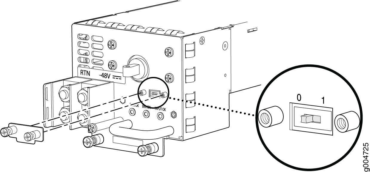
Each DC power supply weighs approximately 3.8 lb (1.7 kg) and consists of one DC input (–48 VDC and return), one 40 A (–48 VDC) circuit breaker, a fan, and LEDs to monitor the status of the power supply. Figure 1 shows the power supply. Each DC power supply has a single DC input (–48 VDC and return) that requires a dedicated circuit breaker.
For high capacity power supplies, we recommend that you provision 60 A or 70 A per feed, depending on the selected DIP switch setting.
You can mix the MX480 high-capacity and normal-capacity power supplies only during the PEM upgrade process. We do not recommend using this configuration in any other cases.
DC Power Supply Configurations
In the DC power configuration, the MX480 router contains either two or four DC power supplies (see Figure 1) located at the rear of the chassis in slots PEM0 through PEM3 (left to right). You can upgrade your DC power system from two to four power supplies.
Four power supplies provide full redundancy. If a DC power supply in a redundant configuration is removed or fails, its redundant power supply takes over without interruption. The DC power supply in PEM2 serves as redundant to the DC power supply in slot PEM0, and the DC power supply in PEM3 serves as redundant to the DC power supply in slot PEM1. If only two DC power supplies are installed, they must be installed in slots PEM0 and PEM1 or in slots PEM2 and PEM3.
Table 1 shows the components that are powered by each DC power supply slot. It applies to existing and high-capacity power supplies.
DC Power Supply Slot |
Power Supply Provides Power to the Following Components |
|---|---|
PEM0 |
Fan tray, DPC slots 0 and 1, and SCB slots 0 and 1 |
PEM1 |
Fan tray and DPC slots 2 through 5 |
PEM2 |
Fan tray, DPC slots 0 and 1, and SCB slots 0 and 1 |
PEM3 |
Fan tray and DPC slots 2 through 5 |
MX480 DC Power Supply LEDs
Each DC power supply faceplate contains three LEDs that indicate the status of the power supply (see Table 2). The power supply status is also reflected in two LEDs on the craft interface.In addition, a power supply failure triggers the red alarm LED on the craft interface.
An SCB must be present for the PWR OK LED to go on.
Label |
Color |
State |
Description |
|---|---|---|---|
PWR OK |
Green |
Off |
Power supply is not functioning normally. Check the INPUT OK LED for more information. |
On |
Power supply is functioning normally. |
||
Yellow |
On |
The main output voltage is out of range (lower limit: 37.5 V to 39.5 V; upper limit: 72.5 V to 76 V). |
|
BRKR ON |
Green |
Off |
DC power supply circuit breaker is turned off. |
On |
DC power input is present and the DC power supply circuit breaker is turned on. |
||
INPUT OK |
Green |
Off |
DC input to the PEM is not present. |
On |
DC input is present and is connected in correct polarity. |
||
Yellow |
On |
DC input is present, but not in valid operating range or connected in reverse polarity. |
DC Power Supply Electrical Specifications for MX240 and MX480
Table 3 lists the DC power supply electrical specifications. Table 4 lists the DC power system specifications.
Item |
Specification |
|
|---|---|---|
| Normal-Capacity Power Supplies | ||
|
Maximum output power |
1600 W |
|
|
DC input current rating |
33.3 A @ –48 V nominal operating voltage |
|
|
Maximum Input Current |
40 A |
|
|
DC input voltage |
Operating Range: –40.5 VDC to –72 VDC Nominal: –48 VDC |
|
|
Efficiency Note:
This value is at full load and nominal voltage. |
~98% |
|
| Maximum Inrush |
The peak of inrush current caused by X-capacitors across input of the PEM shall not exceed 200A for less than 10mSecond. Measurement has to be done with Tektronix current probe and a scope with bandwidth 250MHz. The PEM also shall limit the I²t transient to 5A2S maximum at cold start. No damage shall occur to the PEM from repeated on/off/on cycles under hot or cold conditions. |
|
|
Internal Circuit Breaker |
40 A |
|
| High-Capacity Power Supplies | ||
|
Maximum Input Current |
60 A (DIP=0) |
70 A (DIP=1) |
|
Maximum output power |
2240 W |
2440 W |
|
DC input current rating |
50 A @ -48 VDC normal operating voltage |
54.2 A @ -48 VDC normal operating voltage |
|
DC input voltage |
Operating Range: –40.5 VDC to –72 VDC Nominal: –48 VDC |
|
|
Efficiency Note:
This value is at full load and nominal voltage. |
~98% |
|
| Maximum Inrush |
The peak of inrush current caused by X-capacitors across input of the PEM shall not exceed 200A for less than 10mSecond. Measurement has to be done with Tektronix current probe and a scope with bandwidth 250MHz. The PEM also shall limit the I²t transient to 5A2S maximum at cold start. No damage shall occur to the PEM from repeated on/off/on cycles under hot or cold conditions. |
|
Item |
Normal-Capacity |
High-Capacity |
|
|---|---|---|---|
Redundancy |
2+2 |
1+1 |
|
Output power (maximum) per supply |
1600 W |
60 A (DIP=0) |
70 A (DIP=1) |
2240 W |
2440 W |
||
Output power (maximum) per system |
3200 W |
2240 W |
2240 W |
See Also
DC Power Circuit Breaker Requirements for the MX480 Router
Each DC power supply has a single DC input (–48 VDC and return) that requires a dedicated circuit breaker. If you plan to operate a maximally configured DC-powered router with normal-capacity power supplies, we recommend that you use a dedicated customer site circuit breaker rated for 40 A (–48 VDC) minimum, or as required by local code. If you plan to operate a maximally configured DC-powered router with high-capacity power supplies, we recommend that you use a circuit breaker rated for 70 A (–48 VDC), or as required by local code.
If you plan to operate a DC-powered router at less than the maximum configuration, we recommend that you provision a circuit breaker according to respective National Electrical Code and customer site internal standards to maintain proper level of protection for the current specified above or each DC power supply rated for at least 125% of the continuous current that the system draws at –48 VDC.
DC Power Source Cabling for the MX480 Router
Figure 3 shows a typical DC source cabling arrangement.
The DC power supplies in PEM0 and PEM1 must be powered by dedicated power feeds derived from feed A, and the DC power supplies in PEM2 and PEM3 must be powered by dedicated power feeds derived from feed B. This configuration provides the commonly deployed A/B feed redundancy for the system.
You must ensure that power connections maintain the proper polarity. The power source cables might be labeled (+) and (–) to indicate their polarity. There is no standard color coding for DC power cables. The color coding used by the external DC power source at your site determines the color coding for the leads on the power cables that attach to the terminal studs on each power supply.
For field-wiring connections, use copper conductors only.
Power cords and cables must not block access to device components or drape where people could trip on them.
See Also
DC Power Cable Specifications for the MX480 Router
DC Power Cable Lug Specifications—The accessory box shipped with the router includes the cable lugs that attach to the terminal studs of each power supply (see Figure 4).
Before you install the router, a licensed electrician must attach a cable lug to the grounding and power cables that you supply. A cable with an incorrectly attached lug can damage the router.
The same cable lug is used for the grounding cable.
DC Power Cable Specifications—Table 5 summarizes the specifications for the power cables, which you must supply.
Cable Type |
Quantity and Specification |
|---|---|
Power |
Eight 6-AWG (13.3 mm2), minimum 60°C wire, or as required by the local code |