이 페이지 내용
액티브/패시브 섀시 클러스터 구축
Active/Passive Chassis 클러스터 구축 이해
이 경우 클러스터의 단일 디바이스는 모든 트래픽을 라우팅하는 데 사용되고 다른 디바이스는 장애가 발생한 경우에만 사용됩니다( 그림 1 참조). 장애가 발생하면 백업 디바이스가 기본 디바이스가 되어 모든 전송을 제어합니다.
액티브/패시브 섀시 클러스터 는 동일한 중복 그룹에 모두 할당된 중복 이더넷 인터페이스(reth)를 사용하여 달성할 수 있습니다. 노드의 활성 그룹에 있는 인터페이스 중 하나에 장애가 발생하면 그룹은 비활성으로 선언되고 그룹의 모든 인터페이스가 다른 노드로 장애 조치됩니다.
이 구성은 클러스터의 한 노드만 주어진 시간에 트래픽을 전달하기 때문에 패브릭 링크를 통한 트래픽을 최소화합니다.
참조
예: SRX5800 방화벽에서 액티브/패시브 섀시 클러스터 구성
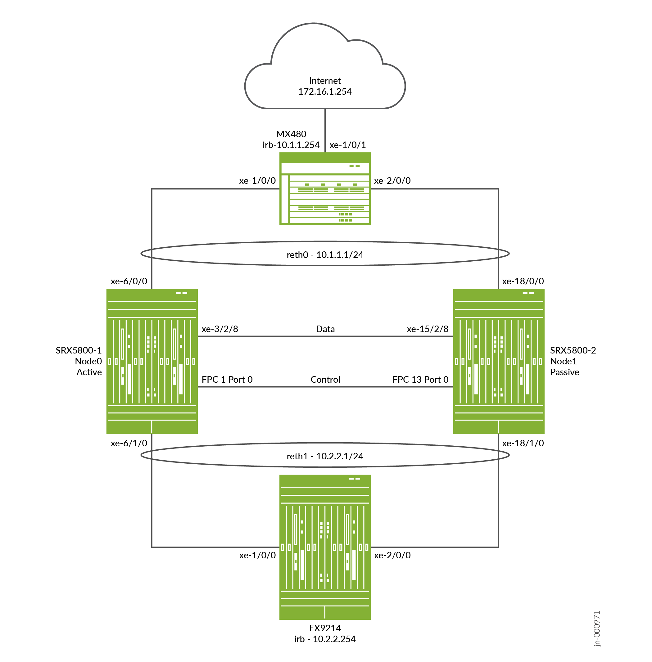
이 예는 SRX5800 방화벽에서 기본 액티브/패시브 섀시 클러스터링을 설정하는 방법을 보여줍니다.
요구 사항
시작하기 전에:
-
하드웨어 구성이 동일한 SRX5800 방화벽 2개가 필요하며, 선택적으로 종단 간 데이터 트래픽을 전송하기 위한 MX480 에지 라우터 1개와 EX9214 이더넷 스위치 1개가 필요합니다.
-
두 디바이스를 물리적으로 연결하고(패브릭 및 제어 포트에 대해 백투백) 동일한 모델인지 확인합니다.
-
클러스터가 형성되기 전에 각 디바이스에 대한 제어 포트를 구성하고 각 디바이스에 클러스터 ID와 노드 ID를 할당한 다음 재부팅해야 합니다. 시스템이 부팅되면 두 노드가 모두 클러스터로 나타납니다.
제어 포트 구성은 SRX5400, SRX5600 및 SRX5800 방화벽에 필요합니다.
이제 장치가 한 쌍입니다. 이 시점부터 클러스터 구성이 노드 구성원 간에 동기화되고 두 개의 개별 장치가 하나의 장치로 작동합니다.
개요
이 예시는 SRX 시리즈 방화벽에서 기본 액티브/패시브 섀시 클러스터링을 설정하는 방법을 보여줍니다. 기본 액티브/패시브 예는 가장 일반적인 유형의 섀시 클러스터입니다.
기본 액티브/패시브 섀시 클러스터는 두 개의 디바이스로 구성됩니다.
-
하나의 디바이스로 라우팅, 방화벽, 네트워크 주소 변환(NAT), VPN 및 보안 서비스를 능동적으로 제공할 뿐만 아니라 섀시 클러스터에 대한 제어를 유지할 수 있습니다.
-
다른 장치는 활성 장치가 비활성 상태가 될 경우 클러스터 장애 조치 기능에 대한 상태를 수동적으로 유지합니다.
SRX5800 방화벽에 대한 이 액티브/패시브 모드 예에서는 네트워크 주소 변환(NAT), 보안 정책 또는 VPN을 구성하는 방법과 같은 기타 구성에 대해 자세히 설명하지 않습니다. 기본적으로 독립 실행형 구성의 경우와 동일합니다. 그러나 섀시 클러스터 구성에서 프록시 ARP를 수행하는 경우, 멤버 인터페이스가 아닌 RETH 인터페이스에 프록시 ARP 구성을 적용해야 합니다. NAT용 프록시 ARP 구성(CLI 절차)을 참조하십시오. 또한 SRX5800 방화벽에서 VLAN 및 트렁크 인터페이스를 사용하여 별도의 논리적 인터페이스 구성을 구성할 수도 있습니다. 이러한 구성은 VLAN 및 트렁크 인터페이스를 사용하는 독립형 구현과 유사합니다.
그림 2 는 이 예에서 사용되는 토폴로지를 보여줍니다.
구성
제어 포트 구성 및 클러스터 모드 활성화
CLI 빠른 구성
이 예를 빠르게 구성하려면, 아래 명령을 복사하여 텍스트 파일로 붙여 넣은 다음 모든 라인브레이크를 제거하고, 네트워크 구성을 일치하는 데 필요한 세부 사항을 바꾸고 계층 수준에서 명령을 CLI [edit] 로 복사해 붙여 넣은 다음, 구성 모드에서 을(를) 입력합니다 commit .
{primary:node0}에서
[edit]
set groups node0 system host-name hostA


                  set groups node0 system backup-router 10.52.63.254


                  set groups node0 system backup-router destination 10.0.0.0/8


                  set groups node0 interfaces fxp0 unit 0 family inet address 10.52.43.57/19


                  set groups node1 system host-name hostB


                  set groups node1 system backup-router 10.52.63.254


                  set groups node1 system backup-router destination 10.0.0.0/8


                  set groups node1 interfaces fxp0 unit 0 family inet address 10.52.52.27/19


                  set apply-groups “${node}”


                  set chassis cluster control-ports fpc 1 port 0


                  set chassis cluster control-ports fpc 13 port 0


                  set chassis cluster control-link-recovery


                  set chassis cluster reth-count 2


                  set chassis cluster redundancy-group 0 node 0 priority 254


                  set chassis cluster redundancy-group 0 node 1 priority 1


                  set chassis cluster redundancy-group 1 node 0 priority 254


                  set chassis cluster redundancy-group 1 node 1 priority 1


                  set chassis cluster redundancy-group 1 interface-monitor xe-6/0/0 weight 255


                  set chassis cluster redundancy-group 1 interface-monitor xe-18/0/0 weight 255


                  set chassis cluster redundancy-group 1 interface-monitor xe-6/1/0 weight 255


                  set chassis cluster redundancy-group 1 interface-monitor xe-18/1/0 weight 255


                  set security policies from-zone trust to-zone untrust policy allow match source-address any


                  set security policies from-zone trust to-zone untrust policy allow match destination-address any


                  set security policies from-zone trust to-zone untrust policy allow match application any


                  set security policies from-zone trust to-zone untrust policy allow then permit


                  set security policies from-zone untrust to-zone trust policy allow match source-address any


                  set security policies from-zone untrust to-zone trust policy allow match destination-address any


                  set security policies from-zone untrust to-zone trust policy allow match application any


                  set security policies from-zone untrust to-zone trust policy allow then permit


                  set security zones security-zone trust host-inbound-traffic system-services ping


                  set security zones security-zone trust interfaces reth1.50


                  set security zones security-zone untrust host-inbound-traffic system-services ping


                  set security zones security-zone untrust interfaces reth0.51


                  set interfaces xe-6/1/0 gigether-options redundant-parent reth1


                  set interfaces xe-6/0/0 gigether-options redundant-parent reth0


                  set interfaces xe-18/1/0 gigether-options redundant-parent reth1


                  set interfaces xe-18/0/0 gigether-options redundant-parent reth0


                  set interfaces fab0 fabric-options member-interfaces xe-3/2/8


                  set interfaces fab1 fabric-options member-interfaces xe-15/2/8


                  set interfaces reth0 vlan-tagging


                  set interfaces reth0 redundant-ether-options redundancy-group 1


                  set interfaces reth0 unit 51 vlan-id 51


                  set interfaces reth0 unit 51 family inet address 10.1.1.1/24


                  set interfaces reth1 vlan-tagging


                  set interfaces reth1 redundant-ether-options redundancy-group 1


                  set interfaces reth1 unit 50 vlan-id 50


                  set interfaces reth1 unit 50 family inet address 10.2.2.1/24


                  set routing-options static route 10.0.0.0/8 next-hop 10.52.63.254


                  set routing-options static route 172.16.1.0/24 next-hop 10.1.1.254
(선택 사항) EX9214 코어 스위치를 빠르게 구성하려면, 아래 명령을 복사하여 텍스트 파일로 붙여 넣은 다음 모든 라인브레이크를 제거하고, 네트워크 구성과 일치시키는 데 필요한 세부 사항을 변경하고 계층 수준에서 명령을 복사하여 CLI [edit] 로 붙여 넣은 다음, 구성 모드의 을(를) 입력합니다 commit .
EX 디바이스에서
[edit]
set interfaces xe-1/0/0 unit 0 family ethernet-switching interface-mode trunk


                  set interfaces xe-1/0/0 unit 0 family ethernet-switching vlan members v50


                  set interfaces xe-2/0/0 unit 0 family ethernet-switching interface-mode trunk


                  set interfaces xe-2/0/0 unit 0 family ethernet-switching vlan members v50


                  set interfaces irb unit 50 family inet address 10.2.2.254/24


                  set routing-options static route 10.1.1.0/24 next-hop 10.2.2.1


                  set routing-options static route 172.16.1.0/24 next-hop 10.2.2.1


                  set vlans v50 vlan-id 50


                  set vlans v50 l3-interface irb.50
(선택 사항)MX480 에지 라우터를 빠르게 구성하려면, 아래 명령을 복사하여 텍스트 파일로 붙여 넣은 다음 모든 라인브레이크를 제거하고, 네트워크 구성과 일치시키는 데 필요한 세부 사항을 변경하고 계층 수준에서 명령을 복사하여 CLI [edit] 로 붙여 넣은 다음, 구성 모드의 을(를) 입력합니다 commit .
MX 디바이스에서
[edit]
set interfaces xe-1/0/0 encapsulation ethernet-bridge


                  set interfaces xe-1/0/0 unit 0 family bridge interface-mode trunk


                  set interfaces xe-1/0/0 unit 0 family bridge vlan-id 51


                  set interfaces xe-1/0/1 unit 0 family inet address 172.16.1.1/24


                  set interfaces xe-2/0/0 encapsulation ethernet-bridge


                  set interfaces xe-2/0/0 unit 0 family bridge interface-mode trunk


                  set interfaces xe-2/0/0 unit 0 family bridge vlan-id 51


                  set interfaces irb unit 0 family inet address 10.1.1.254/24


                  set routing-options static route 10.2.2.0/24 next-hop 10.1.1.1


                  set bridge-domains v51 domain-type bridge


                  set bridge-domains v51 vlan-id 51


                  set bridge-domains v51 routing-interface irb.0
단계별 절차
다음 예제에서는 구성 계층에서 다양한 수준의 탐색이 필요합니다.
SRX 시리즈 방화벽에서 섀시 클러스터를 구성하려면 다음을 수행합니다.
클러스터 모드에서는 명령을 실행할 때 노드 간의 제어 링크를 통해 구성이 동기화됩니다 commit . 모든 명령은 명령이 구성된 디바이스에 관계없이 두 노드에 모두 적용됩니다.
-
SRX5000 방화벽 섀시 클러스터 구성이 하나의 공통된 구성 내에 포함되어 있기 때문에 구성의 일부 요소를 특정 멤버에게만 할당하려면 groups라고 하는 Junos OS 노드별 구성 방법을 사용해야 합니다.
set apply-groups ${node}명령은 노드 변수를 사용하여 그룹이 노드에 적용되는 방법을 정의합니다. 각 노드는 해당 번호를 인식하고 그에 따라 구성을 수락합니다. 또한 클러스터의 개별 컨트롤 플레인에 대해 별도의 IP 주소를 사용하여 SRX5000 방화벽의 fxp0 인터페이스에서 대역 외 관리를 구성해야 합니다.백업 라우터 대상 주소를 x.x.x.0/0으로 구성하는 것은 허용되지 않습니다.
user@hostA# set groups node0 system host-name hostA user@hostA# set groups node0 system backup-router 10.52.63.254 user@hostA# set groups node0 system backup-router destination 10.0.0.0/8 user@hostA# set groups node0 interfaces fxp0 unit 0 family inet address 10.52.43.57/19user@hostB# set groups node1 system host-name hostB user@hostB# set groups node1 system backup-router 10.52.63.254 user@hostB# set groups node1 system backup-router destination 10.0.0.0/8 user@hostB# set groups node1 interfaces fxp0 unit 0 family inet address 10.52.52.27/19위의 그룹 node0 및 node1 구성이 커밋되지만 적용되지 않습니다. 디바이스가 클러스터에 있으면 이러한 명령은 을(를) 사용하여
set apply-groups “${node}”적용됩니다. -
다음 명령을 사용하여 기본인 노드 0을 구성합니다. 노드 구성이 커밋될 때까지 노드 1에 연결할 수 없습니다. 노드 0은 제어 포트를 통해 구성을 노드 1에 자동으로 동기화하며 노드 1을 명시적으로 구성할 필요가 없습니다.
user@hostA# set apply-groups “${node}” -
각 디바이스에 대한 제어 포트를 구성하고 구성을 커밋합니다.
구성에 따라 두 노드의 SPC 카드 간에 물리적 제어 링크 연결이 있는지 확인합니다.
제어 포트는 섀시 내 SPC 위치를 기반으로 파생되며 오프셋 값은 플랫폼을 기반으로 합니다. 아래 예에서 SPC는 수익 슬롯 1에 있으며 SRX5800의 오프셋이 12이므로 제어 포트는 1, 13입니다. 셸 모드에서 명령을 사용하여
“jwhoami -c”특정 플랫폼에 대한 오프셋 값을 볼 수 있습니다. 두 디바이스 모두에 다음 명령을 입력해야 합니다. 예를 들어:-
노드 0에서:
user@hostA# set chassis cluster control-ports fpc 1 port 0 user@hostA# set chassis cluster control-ports fpc 13 port 0 user@hostA# commit -
노드 1에서:
user@hostB# set chassis cluster control-ports fpc 1 port 0
user@hostB# set chassis cluster control-ports fpc 13 port 0
user@hostB# commit
-
-
두 장치를 클러스터 모드로 설정합니다. cluster ID와 노드 ID를 설정한 후 클러스터 모드로 들어가려면 재부팅해야 합니다. CLI 명령줄에서 매개 변수를 포함하여
reboot시스템이 자동으로 부팅되도록 할 수 있습니다. 두 디바이스 모두에서 작동 모드 명령을 입력해야 합니다. 예를 들어:-
노드 0에서:
user@hostA> set chassis cluster cluster-id 1 node 0 reboot -
노드 1에서:
user@hostB> set chassis cluster cluster-id 1 node 1 reboot
클러스터 ID는 클러스터의 두 디바이스에서 동일해야 하지만, 한 디바이스는 노드 0이고 다른 디바이스는 노드 1이므로 노드 ID는 달라야 합니다. 클러스터 ID의 범위는 1에서 255까지입니다. cluster ID를 0으로 설정하는 것은 클러스터를 비활성화하는 것과 같습니다. 그러나 클러스터에서 노드를 분리하는 데 사용하는
set chassis cluster disable것이 좋습니다. -
-
섀시 클러스터링을 위한 중복 그룹을 구성합니다. 각 노드는 인터페이스가 활성 중복 그룹에서 활성화되는 중복 그룹의 인터페이스를 가지고 있습니다(여러 활성 인터페이스가 하나의 중복 그룹에 존재할 수 있음). 중복 그룹 0은 컨트롤 플레인을 제어하고 중복 그룹 1+는 데이터 플레인을 제어하며 데이터 플레인 포트를 포함합니다. 이 액티브/패시브 모드 예에서는 한 번에 하나의 섀시 클러스터 멤버만 활성화되므로 중복 그룹 0과 1만 정의해야 합니다. 중복 그룹 외에도 다음을 정의해야 합니다.
-
중복 이더넷 그룹 - 시스템이 적절한 리소스를 할당할 수 있도록 디바이스에서 활성화될 중복 이더넷 인터페이스(멤버 링크)의 수를 구성합니다.
-
컨트롤 플레인 및 데이터 플레인 우선 순위—컨트롤 플레인에 대한 우선 순위(섀시 클러스터의 경우 높은 우선 순위가 선호됨)를 가진 디바이스와 데이터 플레인에 대해 활성화를 선호하는 디바이스를 정의합니다.
-
액티브/패시브 또는 액티브/액티브 모드에서 컨트롤 플레인(중복 그룹 0)은 데이터 플레인(중복 그룹 1+ 및 그룹) 섀시와 다른 섀시에서 활성화될 수 있습니다. 그러나 이 예에서는 컨트롤 플레인과 데이터 플레인을 모두 동일한 섀시 멤버에서 활성화하는 것이 좋습니다. 트래픽이 다른 멤버 노드로 이동하기 위해 패브릭 링크를 통과하면 지연이 발생합니다(z 라인 모드 트래픽).
-
SRX 시리즈 방화벽(SRX5000 라인)에서 IPsec VPN은 Z 모드의 active/active 섀시 클러스터 구성(즉, 여러 RG1+ 이중화 그룹이 있는 경우)에서 지원되지 않습니다.
-
user@hostA# set chassis cluster reth-count 2 user@hostA# set chassis cluster redundancy-group 1 node 0 priority 254 user@hostA# set chassis cluster redundancy-group 1 node 1 priority 1 user@hostA# set chassis cluster redundancy-group 0 node 0 priority 254 user@hostA# set chassis cluster redundancy-group 0 node 1 priority 1 -
-
액티브/패시브 모드에서 RTO를 전달하는 데 사용되는 클러스터의 패브릭(데이터) 포트를 구성합니다. 이 예에서는 수익 포트 중 하나를 사용합니다. 함께 연결할 두 개의 패브릭 인터페이스를 각 섀시에 하나씩 정의합니다.
데이터 플레인 페일오버 발생 시 다른 섀시 클러스터 멤버가 연결을 원활하게 이어받을 수 있도록 플랫폼에 데이터 인터페이스를 구성합니다. 새로운 액티브 노드로의 원활한 전환은 데이터 플레인 페일오버를 통해 발생합니다. 컨트롤 플레인 페일오버의 경우 모든 데몬이 새 노드에서 다시 시작되므로 피어(ospf, bgp)와의 인접 연결이 손실되지 않도록 그레이스풀 재시작이 가능합니다. 이는 패킷 손실 없이 새로운 노드로 원활하게 전환할 수 있도록 도와줍니다.
다음 항목을 정의해야 합니다.
-
reth 인터페이스에 대한 멤버 인터페이스의 멤버십 정보를 정의합니다.
-
reth 인터페이스가 어떤 중복 그룹의 구성원인지 정의합니다. 이 액티브/패시브 예제의 경우 항상 1입니다.
-
인터페이스의 IP 주소와 같은 reth 인터페이스 정보를 정의합니다.
{primary:node0}[edit]user@hostA# set interfaces xe-6/1/0 gigether-options redundant-parent reth1 user@hostA# set interfaces xe-6/0/0 gigether-options redundant-parent reth0 user@hostA# set interfaces xe-18/1/0 gigether-options redundant-parent reth1 user@hostA# set interfaces xe-18/0/0 gigether-options redundant-parent reth0 user@hostA# set interfaces reth0 vlan-tagging user@hostA# set interfaces reth0 redundant-ether-options redundancy-group 1 user@hostA# set interfaces reth0 unit 51 vlan-id 51 user@hostA# set interfaces reth0 unit 51 family inet address 10.1.1.1/24 user@hostA# set interfaces reth1 vlan-tagging user@hostA# set interfaces reth1 redundant-ether-options redundancy-group 1 user@hostA# set interfaces reth1 unit 50 vlan-id 50 user@hostA# set interfaces reth1 unit 50 family inet address 10.2.2.1/24 user@hostA# set interfaces fab0 fabric-options member-interfaces xe-3/2/8 user@hostA# set interfaces fab1 fabric-options member-interfaces xe-15/2/8 -
-
(선택 사항) 장애 발생 시 섀시 클러스터 동작을 구성합니다. SRX5800 방화벽의 경우 장애 조치 임계값은 255로 설정됩니다. 가중치를 변경하여 섀시 페일오버에 미치는 영향을 확인할 수 있습니다. 또한 제어 링크 복구도 구성해야 합니다. 복구 시 제어 링크가 실패할 경우 보조 노드가 자동으로 재부팅된 다음 다시 온라인으로 전환됩니다. 노드 0에서 다음 명령을 입력합니다.
{primary:node0}[edit]user@hostA# set chassis cluster redundancy-group 1 interface-monitor xe-6/0/0 weight 255 user@hostA# set chassis cluster redundancy-group 1 interface-monitor xe-6/1/0 weight 255 user@hostA# set chassis cluster redundancy-group 1 interface-monitor xe-18/0/0 weight 255 user@hostA# set chassis cluster redundancy-group 1 interface-monitor xe-18/1/0 weight 255 user@hostA# set chassis cluster control-link-recovery이 단계는 SRX5800 방화벽에 대한 액티브/패시브 모드 예시의 섀시 클러스터 구성 부분을 완료합니다. 이 절차의 나머지 부분에서는 구축 시나리오를 완료하기 위해 영역, 가상 라우터, 라우팅, EX9214 코어 스위치 및 MX480 에지 라우터를 구성하는 방법에 대해 설명합니다.
-
(선택 사항) reth 인터페이스를 구성하고 적절한 영역 및 가상 라우터에 연결합니다. 이 예시에서는 추가 구성이 필요 없는 기본 가상 라우터 inet.0에 reth0 및 reth1 인터페이스를 그대로 둡니다.
{primary:node0}[edit]user@hostA# set security zones security-zone trust host-inbound-traffic system-services ping user@hostA# set security zones security-zone trust interfaces reth1.50 user@hostA# set security zones security-zone untrust host-inbound-traffic system-services ping user@hostA# set security zones security-zone untrust interfaces reth0.51 -
트러스트 영역에서 언트러스트(untrust) 영역으로 트래픽을 허용하는 보안 정책을 구축합니다.
user@hostA# set security policies from-zone trust to-zone untrust policy allow match source-address any user@hostA# set security policies from-zone trust to-zone untrust policy allow match destination-address any user@hostA# set security policies from-zone trust to-zone untrust policy allow match application any user@hostA# set security policies from-zone trust to-zone untrust policy allow then permit user@hostA# set security policies from-zone untrust to-zone trust policy allow match source-address any user@hostA# set security policies from-zone untrust to-zone trust policy allow match destination-address any user@hostA# set security policies from-zone untrust to-zone trust policy allow match application any user@hostA# set security policies from-zone untrust to-zone trust policy allow then permit -
(선택 사항) EX9214 이더넷 스위치의 경우 다음 명령은 SRX5800 방화벽에 대한 이 액티브/패시브 모드 예와 관련된 적용 가능한 구성의 개요만 제공합니다. 가장 주목할 만한 것은 VLAN, 라우팅 및 인터페이스 구성입니다.
[edit]user@switch# set interfaces xe-1/0/0 unit 0 family ethernet-switching interface-mode trunk user@switch# set interfaces xe-1/0/0 unit 0 family ethernet-switching vlan members v50 user@switch# set interfaces xe-2/0/0 unit 0 family ethernet-switching interface-mode trunk user@switch# set interfaces xe-2/0/0 unit 0 family ethernet-switching vlan members v50 user@switch# set interfaces irb unit 50 family inet address 10.2.2.254/24 user@switch# set routing-options static route 10.1.1.0/24 next-hop 10.2.2.1 user@switch# set routing-options static route 172.16.1.0/24 next-hop 10.2.2.1 user@switch# set vlans v50 vlan-id 50 user@switch# set vlans v50 l3-interface irb.50 -
(선택 사항) MX480 에지 라우터의 경우, 다음 명령은 SRX5800 방화벽에 대한 이 액티브/패시브 모드 예와 관련된 적용 가능한 구성의 개요만 제공합니다. 특히 스위치의 가상 스위치 인스턴스 내에서 IRB 인터페이스를 사용해야 합니다.
[edit]user@router# set interfaces xe-1/0/0 encapsulation ethernet-bridge user@router# set interfaces xe-1/0/0 unit 0 family bridge interface-mode trunk user@router# set interfaces xe-1/0/0 unit 0 family bridge vlan-id 51 user@router# set interfaces xe-1/0/1 unit 0 family inet address 172.16.1.1/24 user@router# set interfaces xe-2/0/0 encapsulation ethernet-bridge user@router# set interfaces xe-2/0/0 unit 0 family bridge interface-mode trunk user@router# set interfaces xe-2/0/0 unit 0 family bridge vlan-id 51 user@router# set interfaces irb unit 0 family inet address 10.1.1.254/24 user@router# set routing-options static route 10.2.2.0/24 next-hop 10.1.1.1 user@router# set bridge-domains v51 domain-type bridge user@router# set bridge-domains v51 vlan-id 51 user@router# set bridge-domains v51 routing-interface irb.0
확인
구성이 올바르게 작동하고 있는지 확인합니다.
- 섀시 클러스터 상태 확인
- 섀시 클러스터 인터페이스 확인
- 섀시 클러스터 통계 확인
- 섀시 클러스터 컨트롤 플레인 통계 확인
- 섀시 클러스터 데이터 플레인 통계 확인
- EX 디바이스에서 Ping 확인
- 섀시 클러스터 이중화 그룹 상태 확인
- 로그를 통한 문제 해결
섀시 클러스터 상태 확인
목적
섀시 클러스터 상태, 장애 조치 상태 및 중복 그룹 정보를 확인합니다.
행동
운영 모드에서 명령을 입력합니다 show chassis cluster status .
{primary:node0}
user@hostA> show chassis cluster status
Monitor Failure codes:
    CS  Cold Sync monitoring        FL  Fabric Connection monitoring
    GR  GRES monitoring             HW  Hardware monitoring
    IF  Interface monitoring        IP  IP monitoring
    LB  Loopback monitoring         MB  Mbuf monitoring
    NH  Nexthop monitoring          NP  NPC monitoring
    SP  SPU monitoring              SM  Schedule monitoring
    CF  Config Sync monitoring      RE  Relinquish monitoring
    IS  IRQ storm

Cluster ID: 1
Node   Priority Status               Preempt Manual   Monitor-failures

Redundancy group: 0 , Failover count: 1
node0  254      primary              no      no       None
node1  1        secondary            no      no       None

Redundancy group: 1 , Failover count: 1
node0  254      primary              no      no       None
node1  1        secondary            no      no       None
섀시 클러스터 인터페이스 확인
목적
섀시 클러스터 인터페이스에 대한 정보를 확인합니다.
행동
운영 모드에서 명령을 입력합니다 show chassis cluster interfaces .
{primary:node0}
user@hostA> show chassis cluster interfaces
Control link status: Up

Control interfaces:
    Index   Interface   Monitored-Status   Internal-SA   Security
    0       em0         Up                 Disabled      Disabled

Fabric link status: Up

Fabric interfaces:
    Name    Child-interface    Status                    Security
                               (Physical/Monitored)
    fab0    xe-3/2/8           Up   / Up                 Disabled
    fab0
    fab1    xe-15/2/8           Up   / Up                 Disabled
    fab1

Redundant-ethernet Information:
    Name         Status      Redundancy-group
    reth0        Up          1
    reth1        Up          1

Redundant-pseudo-interface Information:
    Name         Status      Redundancy-group
    lo0          Up          0

Interface Monitoring:
    Interface         Weight    Status                    Redundancy-group
                                (Physical/Monitored)
    xe-18/1/0          255       Up  /  Up                 1
    xe-6/1/0          255       Up  /  Up                 1
    xe-18/0/0          255       Up  /  Up                 1
    xe-6/0/0          255       Up  /  Up                 1
섀시 클러스터 통계 확인
목적
섀시 클러스터 서비스 및 제어 링크 통계(전송 및 수신된 하트비트), 패브릭 링크 통계(전송 및 수신된 프로브) 및 서비스에 대해 전송 및 수신된 RTO 수에 대한 정보를 확인합니다.
행동
운영 모드에서 명령을 입력합니다 show chassis cluster statistics .
{primary:node0}
user@hostA> show chassis cluster statistics

Control link statistics:
    Control link 0:
        Heartbeat packets sent: 229414
        Heartbeat packets received: 229385
        Heartbeat packet errors: 0
Fabric link statistics:
    Child link 0
        Probes sent: 459691
        Probes received: 459679
    Child link 1
        Probes sent: 0
        Probes received: 0
Services Synchronized:
    Service name                              RTOs sent    RTOs received
    Translation context                       0            0
    Incoming NAT                              0            0
    Resource manager                          0            0
    DS-LITE create                            0            0
    Session create                            0            0
    IPv6 session create                       0            0
    IPv4/6 session RTO ACK                    0            0
    Session close                             0            0
    IPv6 session close                        0            0
    Session change                            0            0
    IPv6 session change                       0            0
    ALG Support Library                       0            0
    Gate create                               0            0
    Session ageout refresh requests           0            0
    IPv6 session ageout refresh requests      0            0
    Session ageout refresh replies            0            0
    IPv6 session ageout refresh replies       0            0
    IPSec VPN                                 0            0
    Firewall user authentication              0            0
    MGCP ALG                                  0            0
    H323 ALG                                  0            0
    SIP ALG                                   0            0
    SCCP ALG                                  0            0
    PPTP ALG                                  0            0
    JSF PPTP ALG                              0            0
    RPC ALG                                   0            0
    RTSP ALG                                  0            0
    RAS ALG                                   0            0
    MAC address learning                      0            0
    GPRS GTP                                  0            0
    GPRS SCTP                                 0            0
    GPRS FRAMEWORK                            0            0
    JSF RTSP ALG                              0            0
    JSF SUNRPC MAP                            0            0
    JSF MSRPC MAP                             0            0
    DS-LITE delete                            0            0
    JSF SLB                                   0            0
    APPID                                     0            0
    JSF MGCP MAP                              0            0
    JSF H323 ALG                              0            0
    JSF RAS ALG                               0            0
    JSF SCCP MAP                              0            0
    JSF SIP MAP                               0            0
    PST_NAT_CREATE                            0            0
    PST_NAT_CLOSE                             0            0
    PST_NAT_UPDATE                            0            0
    JSF TCP STACK                             0            0
    JSF IKE ALG                               0            0

Packet stats                              Pkts sent    Pkts received
    ICD Data                                  0            0
섀시 클러스터 컨트롤 플레인 통계 확인
목적
섀시 클러스터 컨트롤 플레인 통계(송수신된 하트비트) 및 패브릭 링크 통계(송수신된 프로브)에 대한 정보를 확인합니다.
행동
운영 모드에서 명령을 입력합니다 show chassis cluster control-plane statistics .
{primary:node0}
user@hostA> show chassis cluster control-plane statistics
Control link statistics:
    Control link 0:
        Heartbeat packets sent: 229474
        Heartbeat packets received: 229445
        Heartbeat packet errors: 0
Fabric link statistics:
    Child link 0
        Probes sent: 459809
        Probes received: 459797
    Child link 1
        Probes sent: 0
        Probes received: 0
섀시 클러스터 데이터 플레인 통계 확인
목적
서비스에 대해 보내고 받은 RTO 수에 대한 정보를 확인합니다.
행동
운영 모드에서 명령을 입력합니다 show chassis cluster data-plane statistics .
{primary:node0}
user@hostA> show chassis cluster data-plane statistics
Services Synchronized:
    Service name                              RTOs sent    RTOs received
    Translation context                       0            0
    Incoming NAT                              0            0
    Resource manager                          0            0
    DS-LITE create                            0            0
    Session create                            0            0
    IPv6 session create                       0            0
    Session close                             0            0
    IPv6 session close                        0            0
    Session change                            0            0
    IPv6 session change                       0            0
    ALG Support Library                       0            0
    Gate create                               0            0
    Session ageout refresh requests           0            0
    IPv6 session ageout refresh requests      0            0
    Session ageout refresh replies            0            0
    IPv6 session ageout refresh replies       0            0
    IPSec VPN                                 0            0
    Firewall user authentication              0            0
    MGCP ALG                                  0            0
    H323 ALG                                  0            0
    SIP ALG                                   0            0
    SCCP ALG                                  0            0
    PPTP ALG                                  0            0
    JSF PPTP ALG                              0            0
    RPC ALG                                   0            0
    RTSP ALG                                  0            0
    RAS ALG                                   0            0
    MAC address learning                      0            0
    GPRS GTP                                  0            0
    GPRS SCTP                                 0            0
    GPRS FRAMEWORK                            0            0
    JSF RTSP ALG                              0            0
    JSF SUNRPC MAP                            0            0
    JSF MSRPC MAP                             0            0
    DS-LITE delete                            0            0
    JSF SLB                                   0            0
    APPID                                     0            0
    JSF MGCP MAP                              0            0
    JSF H323 ALG                              0            0
    JSF RAS ALG                               0            0
    JSF SCCP MAP                              0            0
    JSF SIP MAP                               0            0
    PST_NAT_CREATE                            0            0
    PST_NAT_CLOSE                             0            0
    PST_NAT_UPDATE                            0            0
    JSF TCP STACK                             0            0
    JSF IKE ALG                               0            0
EX 디바이스에서 Ping 확인
목적
EX 디바이스에서 연결 상태를 확인합니다.
행동
운영 모드에서 명령을 입력합니다 ping 172.16.1.254 count 2 .
user@EX9214> ping 172.16.1.254 count 2
PING 172.16.1.254 (172.16.1.254): 56 data bytes
64 bytes from 172.16.1.254: icmp_seq=0 ttl=62 time=4.599 ms
64 bytes from 172.16.1.254: icmp_seq=1 ttl=62 time=3.192 ms

--- 172.16.1.254 ping statistics ---
2 packets transmitted, 2 packets received, 0% packet loss
round-trip min/avg/max/stddev = 3.192/3.896/4.599/0.704 ms
섀시 클러스터 이중화 그룹 상태 확인
목적
클러스터에 있는 두 노드의 상태 및 우선 순위를 확인하고 기본 노드가 선점되었는지 또는 수동 장애 조치(failover)가 있었는지 여부에 대한 정보를 확인합니다.
행동
운영 모드에서 명령을 입력합니다 chassis cluster status redundancy-group .
{primary:node0}
user@hostA> show chassis cluster status redundancy-group 1
Monitor Failure codes:
    CS  Cold Sync monitoring        FL  Fabric Connection monitoring
    GR  GRES monitoring             HW  Hardware monitoring
    IF  Interface monitoring        IP  IP monitoring
    LB  Loopback monitoring         MB  Mbuf monitoring
    NH  Nexthop monitoring          NP  NPC monitoring
    SP  SPU monitoring              SM  Schedule monitoring
    CF  Config Sync monitoring      RE  Relinquish monitoring

Cluster ID: 1
Node   Priority Status         Preempt Manual   Monitor-failures

Redundancy group: 1 , Failover count: 1
node0  254      primary        no      no       None
node1  1        secondary      no      no       None
예: 액티브/패시브 섀시 클러스터 페어 구성(SRX1500 또는 SRX1600)
이 예는 SRX1500 또는 SRX1600 디바이스에 대한 액티브/패시브 섀시 클러스터링을 구성하는 방법을 보여줍니다.
요구 사항
시작하기 전에:
한 쌍의 디바이스를 물리적으로 연결하여 동일한 모델인지 확인합니다.
한 디바이스의 기가비트 이더넷 인터페이스를 다른 디바이스의 다른 기가비트 이더넷 인터페이스에 연결하여 패브릭 링크를 생성합니다.
두 SRX1500 디바이스의 제어 포트를 연결하여 제어 링크를 생성합니다.
콘솔 포트를 사용하여 디바이스 중 하나에 연결합니다. (클러스터를 형성하는 노드입니다.) 을 클릭하고 클러스터 ID와 노드 번호를 설정합니다.
user@host> set chassis cluster cluster-id 1 node 0 reboot
콘솔 포트를 사용하여 다른 디바이스에 연결하고 클러스터 ID와 노드 번호를 설정합니다.
user@host> set chassis cluster cluster-id 1 node 1 reboot
개요
이 예에서는 클러스터의 단일 디바이스를 사용하여 모든 트래픽을 라우팅하고 다른 디바이스는 장애 발생 시에만 사용합니다. ( 그림 3 참조) 장애가 발생하면 백업 디바이스가 기본 디바이스가 되어 모든 전송을 제어합니다.
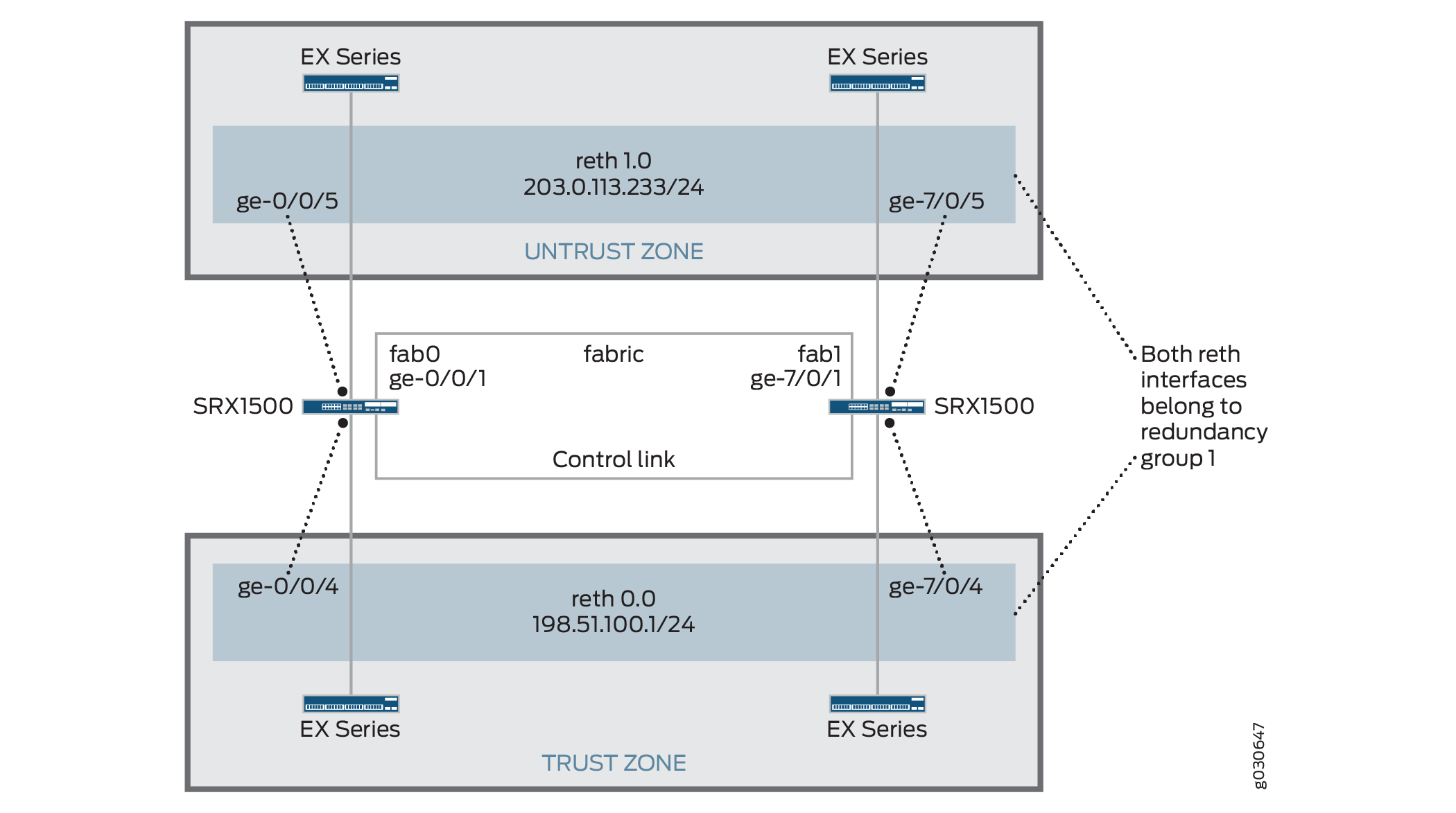
동일한 중복 그룹에 모두 할당된 중복 이더넷 인터페이스(RETH)를 구성하여 액티브/패시브 섀시 클러스터를 생성할 수 있습니다. 이 구성은 클러스터의 한 노드만 주어진 시간에 트래픽을 전달하기 때문에 패브릭 링크를 통한 트래픽을 최소화합니다.
이 예에서는 그룹(명령으로 apply-groups 구성 적용) 및 섀시 클러스터 정보를 구성합니다. 그런 다음 보안 영역과 보안 정책을 구성합니다. 표 1 - 표 4를 참조하십시오.
특징 |
이름 |
구성 매개 변수 |
|---|---|---|
그룹 |
노드 0 |
|
노드 1 |
|
특징 |
이름 |
구성 매개 변수 |
|---|---|---|
패브릭 링크 |
팹0 |
인터페이스: ge-0/0/1 |
팹1 |
인터페이스: ge-7/0/1 |
|
하트비트 간격 |
– |
1000 |
하트비트 임계값 |
– |
3 |
이중화 그룹 |
0 |
|
1 |
|
|
인터페이스 모니터링
|
||
중복 이더넷 인터페이스 수 |
– |
2 |
인터페이스 |
ge-0/0/4 |
중복 상위: reth0 |
ge-7/0/4 |
중복 상위: reth0 |
|
ge-0/0/5 |
중복 상위: reth1 |
|
ge-7/0/5 |
중복 상위: reth1 |
|
reth0 |
이중화 그룹: 1 |
|
|
||
reth1 |
이중화 그룹: 1 |
|
|
이름 |
구성 매개 변수 |
|---|---|
트러스트 |
reth1.0 인터페이스는 이 영역에 결합됩니다. |
불신(untrust) |
reth0.0 인터페이스는 이 영역에 결합됩니다. |
목적 |
이름 |
구성 매개 변수 |
|---|---|---|
이 보안 정책은 트러스트 영역에서 언트러스트(untrust) 영역으로 트래픽을 허용합니다. |
어떤 |
|
구성
절차
CLI 빠른 구성
이 예를 빠르게 구성하려면, 아래 명령을 복사하여 텍스트 파일로 붙여 넣은 다음 모든 라인브레이크를 제거하고, 네트워크 구성을 일치하는 데 필요한 세부 사항을 바꾸고 계층 수준에서 명령을 CLI [edit] 로 복사해 붙여 넣은 다음, 구성 모드에서 을(를) 입력합니다 commit .
[edit]
set groups node0 system host-name srx1500-A
set groups node0 interfaces fxp0 unit 0 family inet address 192.0.2.110/24
set groups node1 system host-name srx1500-B
set groups node1 interfaces fxp0 unit 0 family inet address 192.0.2.111/24
set apply-groups “${node}”
set interfaces fab0 fabric-options member-interfaces ge-0/0/1
set interfaces fab1 fabric-options member-interfaces ge-7/0/1
set chassis cluster heartbeat-interval 1000
set chassis cluster heartbeat-threshold 3
set chassis cluster redundancy-group 0 node 0 priority 100
set chassis cluster redundancy-group 0 node 1 priority 1
set chassis cluster redundancy-group 1 node 0 priority 100
set chassis cluster redundancy-group 1 node 1 priority 1
set chassis cluster redundancy-group 1 interface-monitor ge-0/0/4 weight 255
set chassis cluster redundancy-group 1 interface-monitor ge-7/0/4 weight 255
set chassis cluster redundancy-group 1 interface-monitor ge-0/0/5 weight 255
set chassis cluster redundancy-group 1 interface-monitor ge-7/0/5 weight 255
set chassis cluster reth-count 2
set interfaces ge-0/0/5 gigether-options redundant-parent reth1
set interfaces ge-7/0/5 gigether-options redundant-parent reth1
set interfaces ge-0/0/4 gigether-options redundant-parent reth0
set interfaces ge-7/0/4 gigether-options redundant-parent reth0
set interfaces reth0 redundant-ether-options redundancy-group 1
set interfaces reth0 unit 0 family inet address 198.51.100.1/24
set interfaces reth1 redundant-ether-options redundancy-group 1
set interfaces reth1 unit 0 family inet address 203.0.113.233/24
set security zones security-zone untrust interfaces reth1.0
set security zones security-zone trust interfaces reth0.0
set security policies from-zone trust to-zone untrust policy ANY match source-address any
set security policies from-zone trust to-zone untrust policy ANY match destination-address any
set security policies from-zone trust to-zone untrust policy ANY match application any
set security policies from-zone trust to-zone untrust policy ANY then permit
단계별 절차
액티브/패시브 섀시 클러스터 구성:
관리 인터페이스를 구성합니다.
{primary:node0}[edit]
user@host# set groups node0 system host-name srx1500-A
user@host# set groups node0 interfaces fxp0 unit 0 family inet address 192.0.2.110/24
user@host# set groups node1 system host-name srx1500-B
user@host# set groups node1 interfaces fxp0 unit 0 family inet address 192.0.2.111/24
user@host# set apply-groups “${node}”
패브릭 인터페이스를 구성합니다.
{primary:node0}[edit]
user@host# set interfaces fab0 fabric-options member-interfaces ge-0/0/1
user@host# set interfaces fab1 fabric-options member-interfaces ge-7/0/1
하트비트 설정을 구성합니다.
{primary:node0}[edit]
user@host# set chassis cluster heartbeat-interval 1000
user@host# set chassis cluster heartbeat-threshold 3
중복 그룹을 구성합니다.
{primary:node0}[edit]
user@host# set chassis cluster redundancy-group 0 node 0 priority 100
user@host# set chassis cluster redundancy-group 0 node 1 priority 1
user@host# set chassis cluster redundancy-group 1 node 0 priority 100
user@host# set chassis cluster redundancy-group 1 node 1 priority 1
user@host# set chassis cluster redundancy-group 1 interface-monitor ge-0/0/4 weight 255
user@host# set chassis cluster redundancy-group 1 interface-monitor ge-7/0/4 weight 255
user@host# set chassis cluster redundancy-group 1 interface-monitor ge-0/0/5 weight 255
user@host# set chassis cluster redundancy-group 1 interface-monitor ge-7/0/5 weight 255
중복 이더넷 인터페이스를 구성합니다.
{primary:node0}[edit]
user@host# set chassis cluster reth-count 2
user@host# set interfaces ge-0/0/5 gigether-options redundant-parent reth1
user@host# set interfaces ge-7/0/5 gigether-options redundant-parent reth1
user@host# set interfaces ge-0/0/4 gigether-options redundant-parent reth0
user@host# set interfaces ge-7/0/4 gigether-options redundant-parent reth0
user@host# set interfaces reth0 redundant-ether-options redundancy-group 1
user@host# set interfaces reth0 unit 0 family inet address 198.51.100.1/24
user@host# set interfaces reth1 redundant-ether-options redundancy-group 1
user@host# set interfaces reth1 unit 0 family inet address 203.0.113.233/24
보안 영역을 구성합니다.
{primary:node0}[edit]
user@host# set security zones security-zone untrust interfaces reth1.0
user@host# set security zones security-zone trust interfaces reth0.0
보안 정책을 구성합니다.
{primary:node0}[edit]
user@host# set security policies from-zone trust to-zone untrust policy ANY match source-address any
user@host# set security policies from-zone trust to-zone untrust policy ANY match destination-address any
user@host# set security policies from-zone trust to-zone untrust policy ANY match application any
user@host# set security policies from-zone trust to-zone untrust policy ANY then permit
결과
구성 모드에서 명령을 입력하여 show configuration 구성을 확인합니다. 출력이 의도된 구성을 표시하지 않으면, 이 예의 구성 지침을 반복하여 수정합니다.
간결성을 위해 이 show 명령 출력은 이 예와 관련된 구성만 포함합니다. 시스템의 다른 구성은 생략 부호(...)로 대체되었습니다.
user@host> show configuration
version x.xx.x;
groups {
    node0 {
        system {
            host-name srx1500-A;
        }
        interfaces {
            fxp0 {
                unit 0 {
                    family inet {
                        address 192.0.2.110/24;
                    }
                }
            }
        }
    }
    node1 {
        system {
            host-name srx1500-B;
            interfaces {
                fxp0 {
                    unit 0 {
                        family inet {
                            address 192.0.2.110/24;
                        }
                    }
                }
            }
        }
    }
    apply-groups "${node}";
    chassis {
        cluster {
            reth-count 2;
            heartbeat-interval 1000;
            heartbeat-threshold 3;
            redundancy-group 0 {
                node 0 priority 100;
                node 1 priority 1;
            }
            redundancy-group 1 {
                node 0 priority 100;
                node 1 priority 1;
                interface-monitor {
                    ge–0/0/4 weight 255;
                    ge–7/0/4 weight 255;
                    ge–0/0/5 weight 255;
                    ge–7/0/5 weight 255;
                }
            }
        }
    }
    interfaces {
        ge–0/0/4 {
            gigether–options {
                redundant–parent reth0;
            }
        }
        ge–7/0/4{
            gigether–options {
                redundant–parent reth0;
            }
        }
        ge–0/0/5 {
            gigether–options {
                redundant–parent reth1;
            }
        }
        ge–7/0/5 {
            gigether–options {
                redundant–parent reth1;
            }
        }
        fab0 {
            fabric–options {
                member–interfaces {
                    ge–0/0/1;
                }
            }
        }
        fab1 {
            fabric–options {
                member–interfaces {
                    ge–7/0/1;
                }
            }
        }
        reth0 {
            redundant–ether–options {
                redundancy–group 1;
            }
            unit 0 {
                family inet {
                    address 198.51.100.1/24;
                }
            }
        }
        reth1 {
            redundant–ether–options {
                redundancy–group 1;
            }
            unit 0 {
                family inet {
                    address 203.0.113.233/24;
                }
            }
        }
    }
...
security {
    zones {
        security–zone untrust {
            interfaces {
                reth1.0;
            }
        }
        security–zone trust {
            interfaces {
                reth0.0;
            }
        }
    }
    policies {
        from-zone trust to-zone untrust {
            policy ANY {
                match {
                    source-address any;
                    destination-address any;
                    application any;
                }
                then {
                    permit;
                }
            }
        }
    }
}
디바이스 구성을 마쳤으면 구성 모드에서 을(를) 입력합니다 commit .
확인
구성이 올바르게 작동하고 있는지 확인합니다.
- 섀시 클러스터 상태 확인
- 섀시 클러스터 인터페이스 확인
- 섀시 클러스터 통계 확인
- 섀시 클러스터 컨트롤 플레인 통계 확인
- 섀시 클러스터 데이터 플레인 통계 확인
- 섀시 클러스터 이중화 그룹 상태 확인
- 로그를 통한 문제 해결
섀시 클러스터 상태 확인
목적
섀시 클러스터 상태, 장애 조치 상태 및 중복 그룹 정보를 확인합니다.
행동
운영 모드에서 명령을 입력합니다 show chassis cluster status .
{primary:node0}
user@host> show chassis cluster status
Cluster ID: 1
Node                       Priority     Status    Preempt  Manual failover

Redundancy group: 0 , Failover count: 1
    node0                   100         primary   no       no
    node1                   1           secondary no       no

Redundancy group: 1 , Failover count: 1
    node0                   100         primary   no       no
    node1                   1           secondary no       no
섀시 클러스터 인터페이스 확인
목적
섀시 클러스터 인터페이스에 대한 정보를 확인합니다.
행동
운영 모드에서 명령을 입력합니다 show chassis cluster interfaces .
{primary:node0}
user@host> show chassis cluster interfaces

Control link status: Up

Control interfaces:
    Index   Interface   Monitored-Status   Security
    0       em0         Up                 Disabled
    1       em1         Down               Disabled

Fabric link status: Up

Fabric interfaces:
    Name    Child-interface    Status   Security
    fab0    ge-0/0/1           Up       Disabled
    fab0
    fab1    ge-7/0/1           Up       Disabled
    fab1

Redundant-ethernet Information:
    Name         Status      Redundancy-group
    reth0        Up          1
    reth1        Up          1

Redundant-pseudo-interface Information:
    Name        Status       Redundancy-group
     lo0          Up               1

Interface Monitoring:
    Interface         Weight    Status    Redundancy-group
    ge-0/0/4          255       Up        1
    ge-7/0/4          255       Up        1
    ge-0/0/5          255       Up        1
    ge-7/0/5          255       Up        1
섀시 클러스터 통계 확인
목적
동기화되는 다양한 개체의 통계, 패브릭 및 제어 인터페이스 Hello, 클러스터에서 모니터링되는 인터페이스의 상태에 대한 정보를 확인합니다.
행동
운영 모드에서 명령을 입력합니다 show chassis cluster statistics .
{primary:node0}
user@host> show chassis cluster statistics

Control link statistics:
    Control link 0:
        Heartbeat packets sent: 2276
        Heartbeat packets received: 2280
        Heartbeat packets errors: 0
Fabric link statistics:
    Child link 0
        Probes sent: 2272
        Probes received: 597
Services Synchronized:
    Service name                              RTOs sent    RTOs received
    Translation context                       0            0
    Incoming NAT                              0            0
    Resource manager                          6            0
    Session create                            161          0
    Session close                             148          0
    Session change                            0            0
    Gate create                               0            0
    Session ageout refresh requests           0            0
    Session ageout refresh replies            0            0
    IPSec VPN                                 0            0
    Firewall user authentication              0            0
    MGCP ALG                                  0            0
    H323 ALG                                  0            0
    SIP ALG                                   0            0
    SCCP ALG                                  0            0
    PPTP ALG                                  0            0
    RPC ALG                                   0            0
    RTSP ALG                                  0            0
    RAS ALG                                   0            0
    MAC address learning                      0            0
    GPRS GTP                                  0            0
섀시 클러스터 컨트롤 플레인 통계 확인
목적
섀시 클러스터 컨트롤 플레인 통계(송수신된 하트비트) 및 패브릭 링크 통계(송수신된 프로브)에 대한 정보를 확인합니다.
행동
운영 모드에서 명령을 입력합니다 show chassis cluster control-plane statistics .
{primary:node0}
user@host> show chassis cluster control-plane statistics

Control link statistics:
    Control link 0:
        Heartbeat packets sent: 258689
        Heartbeat packets received: 258684
        Heartbeat packets errors: 0
Fabric link statistics:
    Child link 0
        Probes sent: 258681
        Probes received: 258681
섀시 클러스터 데이터 플레인 통계 확인
목적
서비스에 대해 보내고 받은 RTO 수에 대한 정보를 확인합니다.
행동
운영 모드에서 명령을 입력합니다 show chassis cluster data-plane statistics .
{primary:node0}
user@host> show chassis cluster data-plane statistics

Services Synchronized:
    Service name                              RTOs sent    RTOs received
    Translation context                       0            0
    Incoming NAT                              0            0
    Resource manager                          6            0
    Session create                            161          0
    Session close                             148          0
    Session change                            0            0
    Gate create                               0            0
    Session ageout refresh requests           0            0
    Session ageout refresh replies            0            0
    IPSec VPN                                 0            0
    Firewall user authentication              0            0
    MGCP ALG                                  0            0
    H323 ALG                                  0            0
    SIP ALG                                   0            0
    SCCP ALG                                  0            0
    PPTP ALG                                  0            0
    RPC ALG                                   0            0
    RTSP ALG                                  0            0
    RAS ALG                                   0            0
    MAC address learning                      0            0
    GPRS GTP                                  0            0
섀시 클러스터 이중화 그룹 상태 확인
목적
클러스터에 있는 두 노드의 상태 및 우선 순위를 확인하고 기본 노드가 선점되었는지 또는 수동 장애 조치(failover)가 있었는지 여부에 대한 정보를 확인합니다.
행동
운영 모드에서 명령을 입력합니다 chassis cluster status redundancy-group .
{primary:node0}
user@host> show chassis cluster status redundancy-group 1
Cluster ID: 1
    Node               Priority    Status    Preempt  Manual failover

	Redundancy-Group: 1, Failover count: 1
    node0              100          primary   no       no
    node1              1            secondary no       no
예: J-Web(Active/Passive Chassis Cluster Pair) 구성
클러스터링을 활성화합니다. 예: 액티브/패시브 섀시 클러스터 페어(CLI) 구성의 1단계를 참조하십시오.
관리 인터페이스를 구성합니다. 예제: 액티브/패시브 섀시 클러스터 페어(CLI) 구성의 2단계를 참조하십시오.
패브릭 인터페이스를 구성합니다. 예제: 액티브/패시브 섀시 클러스터 페어(CLI) 구성의 3단계를 참조하십시오.
중복 그룹을 구성합니다.
을 선택합니다
Configure>Chassis Cluster.다음 정보를 입력하고 을 클릭합니다.
Apply중복 ether-interface 수:
2하트비트 간격:
1000하트비트 임계값:
3노드:
0그룹 번호:
0우선 순위:
100
다음 정보를 입력하고 을 클릭합니다.
Apply노드:
0그룹 번호:
1우선 순위:
1
다음 정보를 입력하고 을 클릭합니다.
Apply노드:
1그룹 번호:
0우선 순위:
100
중복 이더넷 인터페이스를 구성합니다.
을 선택합니다
Configure>Chassis Cluster.을 선택합니다
ge-0/0/4.Redundant Parent(중복 부모) 상자에 을 입력합니다
reth1.을 누르십시오
Apply.을 선택합니다
ge-7/0/4.Redundant Parent(중복 부모) 상자에 을 입력합니다
reth1.을 누르십시오
Apply.을 선택합니다
ge-0/0/5.Redundant Parent(중복 부모) 상자에 을 입력합니다
reth0.을 누르십시오
Apply.을 선택합니다
ge-7/0/5.Redundant Parent(중복 부모) 상자에 을 입력합니다
reth0.을 누르십시오
Apply.마지막 4개의 구성 설정은 예: 액티브/패시브 섀시 클러스터 페어(CLI) 구성 의 5단계를 참조하십시오.
보안 영역을 구성합니다. 예제: 액티브/패시브 섀시 클러스터 페어(CLI) 구성의 6단계를 참조하십시오.
보안 정책을 구성합니다. 예제: 액티브/패시브 섀시 클러스터 페어(CLI) 구성의 7단계를 참조하십시오.
을(를) 클릭하여
OK구성을 확인하고 후보 구성으로 저장한 다음 >Commit를 클릭합니다Commit Options.
참조
IPsec 터널을 사용한 액티브/패시브 섀시 클러스터 구축 이해
이 경우 클러스터의 단일 디바이스는 IPsec 터널에서 종료되어 모든 트래픽을 처리하는 데 사용되는 반면 다른 디바이스는 장애가 발생한 경우에만 사용됩니다( 그림 4 참조). 장애가 발생하면 백업 디바이스가 기본 디바이스가 되어 모든 전송을 제어합니다.
액티브/패시브 섀시 클러스터 는 동일한 중복 그룹에 모두 할당된 중복 이더넷 인터페이스(reth)를 사용하여 달성할 수 있습니다. 노드의 활성 그룹에 있는 인터페이스 중 하나에 장애가 발생하면 그룹은 비활성으로 선언되고 그룹의 모든 인터페이스가 다른 노드로 장애 조치됩니다.
이 구성은 중복 이더넷 인터페이스가 터널 엔드포인트로 사용되는 액티브/패시브 클러스터에서 사이트 간 IPsec 터널이 종료되는 방법을 제공합니다. 장애가 발생하면 백업 SRX 시리즈 방화벽의 중복 이더넷 인터페이스가 활성화되어 터널이 엔드포인트를 변경하여 새로운 활성 SRX 시리즈 방화벽에서 종료되도록 합니다. 터널 키와 세션 정보가 섀시 클러스터의 구성원 간에 동기화되기 때문에 페일오버 시 터널을 재협상할 필요가 없으며 설정된 모든 세션이 유지됩니다.
RG0(라우팅 엔진) 실패의 경우 라우팅 프로토콜은 새로운 기본 노드에서 다시 설정해야 합니다. VPN 모니터링 또는 Dead-peer-detection이 구성되고 라우팅이 새 RG0 Primary로 다시 통합되기 전에 타이머가 만료되면 VPN 터널이 중단되고 재협상됩니다.
동적 터널은 서로 다른 SPC 간에 로드 밸런싱을 수행할 수 없습니다.
참조
예: IPsec 터널을 사용하여 Active/Passive Chassis 클러스터 쌍 구성
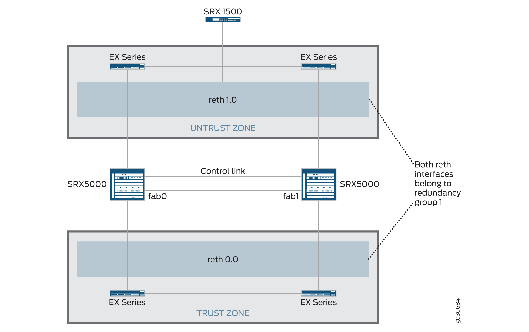
이 예에서는 SRX 시리즈 방화벽에서 IPsec 터널을 사용하여 액티브/패시브 섀시 클러스터링을 구성하는 방법을 보여 줍니다.
요구 사항
시작하기 전에:
-
하드웨어 구성이 동일한 SRX5000 모델 2개, SRX1500 또는 SRX1600 디바이스 1개, EX 시리즈 이더넷 스위치 4개가 제공됩니다.
-
두 디바이스를 물리적으로 연결하고(패브릭 및 제어 포트에 대해 백투백) 동일한 모델인지 확인합니다. SRX5000 라인에서 패브릭 및 컨트롤 포트를 모두 구성할 수 있습니다.
-
두 디바이스를 클러스터 모드로 설정하고 디바이스를 재부팅합니다. 두 디바이스 모두에 다음 운영 모드 명령을 입력해야 합니다. 예를 들면 다음과 같습니다.
-
노드 0에서:
user@host> set chassis cluster cluster-id 1 node 0 reboot -
노드 1에서:
user@host> set chassis cluster cluster-id 1 node 1 reboot
클러스터 ID는 두 디바이스에서 동일하지만, 한 디바이스는 노드 0이고 다른 디바이스는 노드 1이므로 노드 ID가 달라야 합니다. 클러스터 ID의 범위는 1에서 255까지입니다. cluster ID를 0으로 설정하는 것은 클러스터를 비활성화하는 것과 같습니다.
15보다 큰 클러스터 ID는 패브릭 및 제어 링크 인터페이스가 백투백으로 연결된 경우에만 설정할 수 있습니다.
-
-
하드웨어 구성이 동일한 SRX5000 모델 2개, SRX1500 에지 라우터 1개, EX 시리즈 이더넷 스위치 4개가 제공됩니다.
-
두 디바이스를 물리적으로 연결하고(패브릭 및 제어 포트에 대해 백투백) 동일한 모델인지 확인합니다. SRX5000 라인에서 패브릭 및 컨트롤 포트를 모두 구성할 수 있습니다.
이 시점부터 노드 구성원 간에 클러스터 구성이 동기화되고 두 개의 개별 장치가 하나의 장치로 작동합니다. 구성원별 구성(예: 각 구성원의 관리 포트의 IP 주소)은 구성 그룹을 사용하여 입력됩니다.
개요
이 예에서 클러스터의 단일 디바이스는 IPsec 터널에서 종료되어 모든 트래픽을 처리하는 데 사용되며, 다른 디바이스는 장애 시에만 사용됩니다. ( 그림 5 참조) 장애가 발생하면 백업 디바이스가 기본 디바이스가 되어 모든 전송을 제어합니다.
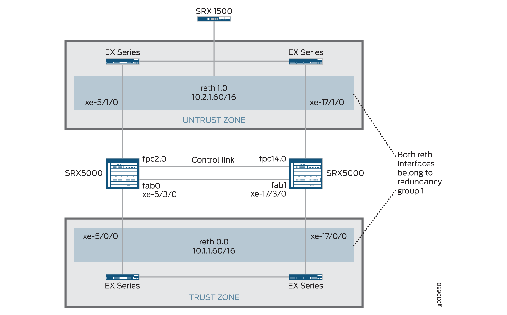
이 예에서는 그룹(명령으로 apply-groups 구성 적용) 및 섀시 클러스터 정보를 구성합니다. 그런 다음 IKE(Internet Key Exchange), IPSec, 정적 경로, 보안 영역 및 보안 정책 매개 변수를 구성합니다. 표 5 - 표 11을 참조하십시오.
| 특징 |
이름 |
구성 매개 변수 |
|---|---|---|
| 그룹 |
노드 0 |
|
| 노드 1 |
|
| 특징 |
이름 |
구성 매개 변수 |
|---|---|---|
| 패브릭 링크 |
팹0 |
인터페이스: xe-5/3/0 |
| 팹1 |
인터페이스: xe-17/3/0 |
|
| 중복 이더넷 인터페이스 수 |
– |
2 |
| 하트비트 간격 |
– |
1000 |
| 하트비트 임계값 |
– |
3 |
| 이중화 그룹 |
0 |
|
| 1 |
|
|
| 인터페이스 모니터링
|
||
| 인터페이스 |
xe-5/1/0 |
중복 상위: reth1 |
| xe-5/1/0 |
중복 상위: reth1 |
|
| xe-5/0/0 |
중복 상위: reth0 |
|
| xe-17/0/0 |
중복 상위: reth0 |
|
| reth0 |
이중화 그룹: 1 |
|
|
||
| reth1 |
이중화 그룹: 1 |
|
|
||
| st0 (영문) |
||
|
| 특징 |
이름 |
구성 매개 변수 |
|---|---|---|
| 제안 |
제안 세트 표준 |
- |
| 정책 |
미리 공유한 |
|
| 게이트웨이 |
SRX1500-1 |
메모:
SRX 섀시 클러스터링에서는 IKE 외부 인터페이스 구성에 대해 reth 및 lo0 인터페이스만 지원됩니다. 다른 인터페이스 유형을 구성할 수 있지만 IPSec VPN이 작동하지 않을 수 있습니다. lo0 논리 인터페이스가 IKE 게이트웨이 외부 인터페이스로 사용되는 경우 RG0으로 구성할 수 없습니다. |
| 특징 |
이름 |
구성 매개 변수 |
|---|---|---|
| 제안 |
제안 세트 표준 |
– |
| 정책 |
성병 |
– |
| VPN |
SRX1500-1 |
메모:
수동 VPN 이름과 사이트 간 게이트웨이 이름은 같을 수 없습니다. |
st0.16000에서 st0.16385까지의 보안 터널 인터페이스(st0)는 멀티노드 고가용성(HA) 및 섀시 클러스터에서의 고가용성(HA) 제어 링크 암호화를 위해 예약되어 있습니다. 이러한 인터페이스는 사용자가 구성할 수 없습니다. st0.0에서 st0.15999까지의 인터페이스만 사용할 수 있습니다.
| 이름 |
구성 매개 변수 |
|---|---|
| 0.0.0.0/0 |
다음 홉: 10.2.1.1 |
| 10.3.0.0/16 |
다음 홉: 10.10.1.2 |
| 이름 |
구성 매개 변수 |
|---|---|
| 트러스트 |
|
| 불신(untrust) |
|
| VPN |
|
| 목적 |
이름 |
구성 매개 변수 |
|---|---|---|
| 이 보안 정책은 트러스트 영역에서 언트러스트(untrust) 영역으로 트래픽을 허용합니다. |
어떤 |
|
| 이 보안 정책은 트러스트 영역에서 VPN 영역으로 트래픽을 허용합니다. |
vpn-any |
|
구성
절차
CLI 빠른 구성
이 예를 빠르게 구성하려면, 아래 명령을 복사하여 텍스트 파일로 붙여 넣은 다음 모든 라인브레이크를 제거하고, 네트워크 구성을 일치하는 데 필요한 세부 사항을 바꾸고 계층 수준에서 명령을 CLI [edit] 로 복사해 붙여 넣은 다음, 구성 모드에서 을(를) 입력합니다 commit .
{primary:node0}[edit]
set chassis cluster control-ports fpc 2 port 0


                  set chassis cluster control-ports fpc 14 port 0


                  set groups node0 system host-name SRX5800-1


                  set groups node0 interfaces fxp0 unit 0 family inet address 172.19.100.50/24


                  set groups node1 system host-name SRX5800-2


                  set groups node1 interfaces fxp0 unit 0 family inet address 172.19.100.51/24


                  set apply-groups “${node}”


                  set interfaces fab0 fabric-options member-interfaces xe-5/3/0


                  set interfaces fab1 fabric-options member-interfaces xe-17/3/0


                  set chassis cluster reth-count 2


                  set chassis cluster heartbeat-interval 1000


                  set chassis cluster heartbeat-threshold 3


                  set chassis cluster node 0


                  set chassis cluster node 1


                  set chassis cluster redundancy-group 0 node 0 priority 254


                  set chassis cluster redundancy-group 0 node 1 priority 1


                  set chassis cluster redundancy-group 1 node 0 priority 254


                  set chassis cluster redundancy-group 1 node 1 priority 1


                  set chassis cluster redundancy-group 1 preempt


                  set chassis cluster redundancy-group 1 interface-monitor xe-5/0/0 weight 255


                  set chassis cluster redundancy-group 1 interface-monitor xe-5/1/0 weight 255


                  set chassis cluster redundancy-group 1 interface-monitor xe-17/0/0 weight 255


                  set chassis cluster redundancy-group 1 interface-monitor xe-17/1/0 weight 255


                  set interfaces xe-5/1/0 gigether-options redundant-parent reth1


                  set interfaces xe-17/1/0 gigether-options redundant-parent reth1


                  set interfaces xe-5/0/0 gigether-options redundant-parent reth0


                  set interfaces xe-17/0/0 gigether-options redundant-parent reth0


                  set interfaces reth0 redundant-ether-options redundancy-group 1


                  set interfaces reth0 unit 0 family inet address 10.1.1.60/16


                  set interfaces reth1 redundant-ether-options redundancy-group 1


                  set interfaces reth1 unit 0 family inet address 10.2.1.60/16


                  set interfaces st0 unit 0 multipoint family inet address 10.10.1.1/30


                  set security ike policy preShared mode main


                  set security ike policy preShared proposal-set standard


                  set security ike policy preShared pre-shared-key ascii-text "$ABC123"## Encrypted password


                  set security ike gateway SRX1500-1 ike-policy preShared


                  set security ike gateway SRX1500-1 address 10.1.1.90


                  set security ike gateway SRX1500-1 external-interface reth0.0


                  set security ipsec policy std proposal-set standard


                  set security ipsec vpn SRX1500-1 bind-interface st0.0


                  set security ipsec vpn SRX1500-1 vpn-monitor optimized


                  set security ipsec vpn SRX1500-1 ike gateway SRX1500-1


                  set security ipsec vpn SRX1500-1 ike ipsec-policy std


                  set security ipsec vpn SRX1500-1 establish-tunnels immediately


                  set routing-options static route 0.0.0.0/0 next-hop 10.2.1.1


                  set routing-options static route 10.3.0.0/16 next-hop 10.10.1.2


                  set security zones security-zone untrust host-inbound-traffic system-services all


                  set security zones security-zone untrust host-inbound-traffic protocols all


                  set security zones security-zone untrust interfaces reth1.0


                  set security zones security-zone trust host-inbound-traffic system-services all


                  set security zones security-zone trust host-inbound-traffic protocols all


                  set security zones security-zone trust interfaces reth0.0


                  set security zones security-zone vpn host-inbound-traffic system-services all 144


                  set security zones security-zone vpn host-inbound-traffic protocols all


                  set security zones security-zone vpn interfaces st0.0


                  set security policies from-zone trust to-zone untrust policy ANY match source-address any


                  set security policies from-zone trust to-zone untrust policy ANY match destination-address any


                  set security policies from-zone trust to-zone untrust policy ANY match application any


                  set security policies from-zone trust to-zone vpn policy vpn-any then permit
단계별 절차
IPsec 터널이 있는 액티브/패시브 섀시 클러스터 페어를 구성하려면,
-
제어 포트를 구성합니다.
{primary:node0}[edit] user@host# set chassis cluster control-ports fpc 2 port 0 user@host# set chassis cluster control-ports fpc 14 port 0 -
관리 인터페이스를 구성합니다.
{primary:node0}[edit] user@host# set groups node0 system host-name SRX5800-1 user@host# set groups node0 interfaces fxp0 unit 0 family inet address 172.19.100.50/24 user@host#set groups node1 system host-name SRX5800-2 user@host# set groups node1 interfaces fxp0 unit 0 family inet address 172.19.100.51/24 user@host# set apply-groups “${node}” -
패브릭 인터페이스를 구성합니다.
{primary:node0}[edit] user@host# set interfaces fab0 fabric-options member-interfaces xe-5/3/0 user@host# set interfaces fab1 fabric-options member-interfaces xe-17/3/0 -
중복 그룹을 구성합니다.
{primary:node0}[edit] user@host# set chassis cluster reth-count 2 user@host# set chassis cluster heartbeat-interval 1000 user@host# set chassis cluster heartbeat-threshold 3 user@host# set chassis cluster node 0 user@host# set chassis cluster node 1 user@host# set chassis cluster redundancy-group 0 node 0 priority 254 user@host# set chassis cluster redundancy-group 0 node 1 priority 1 user@host# set chassis cluster redundancy-group 1 node 0 priority 254 user@host# set chassis cluster redundancy-group 1 node 1 priority 1 user@host# set chassis cluster redundancy-group 1 preempt user@host# set chassis cluster redundancy-group 1 interface-monitor xe-5/0/0 weight 255 user@host# set chassis cluster redundancy-group 1 interface-monitor xe-5/1/0 weight 255 user@host# set chassis cluster redundancy-group 1 interface-monitor xe-17/0/0 weight 255 user@host# set chassis cluster redundancy-group 1 interface-monitor xe-17/1/0 weight 255 -
중복 이더넷 인터페이스를 구성합니다.
{primary:node0}[edit] user@host# set interfaces xe-5/1/0 gigether-options redundant-parent reth1 user@host# set interfaces xe-17/1/0 gigether-options redundant-parent reth1 user@host# set interfaces xe-5/0/0 gigether-options redundant-parent reth0 user@host# set interfaces xe-17/0/0 gigether-options redundant-parent reth0 user@host# set interfaces reth0 redundant-ether-options redundancy-group 1 user@host# set interfaces reth0 unit 0 family inet address 10.1.1.60/16 user@host# set interfaces reth1 redundant-ether-options redundancy-group 1 user@host# set interfaces reth1 unit 0 family inet address 10.2.1.60/16 -
IPsec 매개 변수를 구성합니다.
{primary:node0}[edit] user@host# set interfaces st0 unit 0 multipoint family inet address 10.10.1.1/30 user@host# set security ike policy preShared mode main user@host# set security ike policy preShared proposal-set standard user@host# set security ike policy preShared pre-shared-key ascii-text "$ABC123"## Encrypted password user@host# set security ike gateway SRX1500-1 ike-policy preShared user@host# set security ike gateway SRX1500-1 address 10.1.1.90 user@host# set security ike gateway SRX1500-1 external-interface reth0.0 user@host# set security ipsec policy std proposal-set standard user@host# set security ipsec vpn SRX1500-1 bind-interface st0.0 user@host# set security ipsec vpn SRX1500-1 vpn-monitor optimized user@host# set security ipsec vpn SRX1500-1 ike gateway SRX1500-1 user@host# set security ipsec vpn SRX1500-1 ike ipsec-policy std user@host# set security ipsec vpn SRX1500-1 establish-tunnels immediately -
정적 경로를 구성합니다.
{primary:node0}[edit] user@host# set routing-options static route 0.0.0.0/0 next-hop 10.2.1.1 user@host# set routing-options static route 10.3.0.0/16 next-hop 10.10.1.2 -
보안 영역을 구성합니다.
{primary:node0}[edit] user@host# set security zones security-zone untrust host-inbound-traffic system-services all user@host# set security zones security-zone untrust host-inbound-traffic protocols all user@host# set security zones security-zone untrust interfaces reth1.0 user@host# set security zones security-zone trust host-inbound-traffic system-services all user@host# set security zones security-zone trust host-inbound-traffic protocols all user@host# set security zones security-zone trust interfaces reth0.0 user@host# set security zones security-zone vpn host-inbound-traffic system-services all user@host# set security zones security-zone vpn host-inbound-traffic protocols all user@host# set security zones security-zone vpn interfaces st0.0 -
보안 정책을 구성합니다.
{primary:node0}[edit]
user@host# set security policies from-zone trust to-zone untrust policy ANY match source-address any
user@host# set security policies from-zone trust to-zone untrust policy ANY match destination-address any
user@host# set security policies from-zone trust to-zone untrust policy ANY match application any
user@host# set security policies from-zone trust to-zone vpn policy vpn-any then permit
결과
운영 모드에서 명령을 입력하여 show configuration 구성을 확인합니다. 출력이 의도된 구성을 표시하지 않으면, 이 예의 구성 지침을 반복하여 수정합니다.
간결성을 위해 이 show 명령 출력은 이 예와 관련된 구성만 포함합니다. 시스템의 다른 구성은 생략 부호(...)로 대체되었습니다.
user@host> show configuration
version x.xx.x;
groups {
node0 {
system {
host-name SRX58001;
}
interfaces {
fxp0 {
unit 0 {
family inet {
address 172.19.100.50/24;
}
}
}
}
}
node1 {
system {
host-name SRX58002;
}
interfaces {
fxp0 {
unit 0 {
family inet {
address 172.19.100.51/24;
}
}
}
}
}
}
apply-groups "${node}";
system {
root-authentication {
encrypted-password "$ABC123";
}
}
chassis {
cluster {
reth-count 2;
heartbeat-interval 1000;
heartbeat-threshold 3;
control-ports {
fpc 2 port 0;
fpc 14 port 0;
}
redundancy-group 0 {
node 0 priority 254;
node 1 priority 1;
}
redundancy-group 1 {
node 0 priority 254;
node 1 priority 1;
preempt;
interface-monitor {
xe–6/0/0 weight 255;
xe–6/1/0 weight 255;
xe–18/0/0 weight 255;
xe–18/1/0 weight 255;
}
}
}
}
interfaces {
xe–5/0/0 {
gigether–options {
redundant–parent reth0;
}
}
xe–5/1/0 {
gigether–options {
redundant–parent reth1;
}
}
xe–17/0/0 {
gigether–options {
redundant–parent reth0;
}
}
xe–17/1/0 {
gigether–options {
redundant–parent reth1;
}
}
fab0 {
fabric–options {
member–interfaces {
xe–5/3/0;
}
}
}
fab1 {
fabric–options {
member–interfaces {
xe–17/3/0;
}
}
}
reth0 {
redundant–ether–options {
redundancy–group 1;
}
unit 0 {
family inet {
address 10.1.1.60/16;
}
}
}
reth1 {
redundant–ether–options {
redundancy–group 1;
}
unit 0 {
family inet {
address 10.2.1.60/16;
}
}
}
st0 {
unit 0 {
multipoint;
family inet {
address 5.4.3.2/32;
}
}
}
}
routing–options {
static {
route 0.0.0.0/0 {
next–hop 10.2.1.1;
}
route 10.3.0.0/16 {
next–hop 10.10.1.2;
}
}
}
security {
zones {
security–zone trust {
host–inbound–traffic {
system–services {
all;
}
}
interfaces {
reth0.0;
}
}
security–zone untrust
host-inbound-traffic {
system-services {
all;
}
}
protocols {
all;
}
interfaces {
reth1.0;
}
}
security-zone vpn {
host-inbound-traffic {
system-services {
all;
}
}
protocols {
all;
}
interfaces {
st0.0;
}
}
}
policies {
from–zone trust to–zone untrust {
policy ANY {
match {
source–address any;
destination–address any;
application any;
}
then {
permit;
}
}
}
from–zone trust to–zone vpn {
policy vpn {
match {
source–address any;
destination–address any;
application any;
}
then {
permit;
}
}
}
}
}
디바이스 구성을 마쳤으면 구성 모드에서 을(를) 입력합니다 commit .
확인
구성이 올바르게 작동하고 있는지 확인합니다.
- 섀시 클러스터 상태 확인
- 섀시 클러스터 인터페이스 확인
- 섀시 클러스터 통계 확인
- 섀시 클러스터 컨트롤 플레인 통계 확인
- 섀시 클러스터 데이터 플레인 통계 확인
- 섀시 클러스터 이중화 그룹 상태 확인
- 로그를 통한 문제 해결
섀시 클러스터 상태 확인
목적
섀시 클러스터 상태, 장애 조치 상태 및 중복 그룹 정보를 확인합니다.
행동
운영 모드에서 명령을 입력합니다 show chassis cluster status .
{primary:node0}
show chassis cluster status
Cluster ID: 1
Node                      Priority     Status    Preempt  Manual failover

Redundancy group: 0 , Failover count: 1
    node0                   1          primary   no       no
    node1                   254        secondary no       no

Redundancy group: 1 , Failover count: 1
    node0                   1          primary   yes      no
    node1                   254        secondary yes      no
섀시 클러스터 인터페이스 확인
목적
섀시 클러스터 인터페이스를 확인합니다.
행동
운영 모드에서 명령을 입력합니다 show chassis cluster interfaces .
{primary:node0}
user@host> show chassis cluster interfaces
Control link name: fxp1

Redundant-ethernet Information:
    Name         Status      Redundancy-group
    reth0        Up          1
    reth1        Up          1

Interface Monitoring:
    Interface         Weight    Status    Redundancy-group
    xe-5/0/0          255       Up        1
    xe-5/1/0          255       Up        1
    xe-17/0/0         255       Up        1
    xe-17/1/0         255       Up        1
섀시 클러스터 통계 확인
목적
섀시 클러스터 서비스 및 제어 링크 통계(전송 및 수신된 하트비트), 패브릭 링크 통계(전송 및 수신된 프로브) 및 서비스에 대해 전송 및 수신된 RTO 수에 대한 정보를 확인합니다.
행동
운영 모드에서 명령을 입력합니다 show chassis cluster statistics .
{primary:node0}
user@host> show chassis cluster statistics

Control link statistics:
    Control link 0:
        Heartbeat packets sent: 258689
        Heartbeat packets received: 258684
        Heartbeat packets errors: 0
Fabric link statistics:
    Child link 0
        Probes sent: 258681
        Probes received: 258681
Services Synchronized:
    Service name                              RTOs sent    RTOs received
    Translation context                       0            0
    Incoming NAT                              0            0
    Resource manager                          6            0
    Session create                            161          0
    Session close                             148          0
    Session change                            0            0
    Gate create                               0            0
    Session ageout refresh requests           0            0
    Session ageout refresh replies            0            0
    IPSec VPN                                 0            0
    Firewall user authentication              0            0
    MGCP ALG                                  0            0
    H323 ALG                                  0            0
    SIP ALG                                   0            0
    SCCP ALG                                  0            0
    PPTP ALG                                  0            0
    RPC ALG                                   0            0
    RTSP ALG                                  0            0
    RAS ALG                                   0            0
    MAC address learning                      0            0
    GPRS GTP                                  0            0
섀시 클러스터 컨트롤 플레인 통계 확인
목적
섀시 클러스터 컨트롤 플레인 통계(송수신된 하트비트) 및 패브릭 링크 통계(송수신된 프로브)에 대한 정보를 확인합니다.
행동
운영 모드에서 명령을 입력합니다 show chassis cluster control-panel statistics .
{primary:node0}
user@host> show chassis cluster control-plane statistics

Control link statistics:
    Control link 0:
        Heartbeat packets sent: 258689
        Heartbeat packets received: 258684
        Heartbeat packets errors: 0
Fabric link statistics:
    Child link 0
        Probes sent: 258681
        Probes received: 258681
섀시 클러스터 데이터 플레인 통계 확인
목적
서비스에 대해 보내고 받은 RTO 수에 대한 정보를 확인합니다.
행동
운영 모드에서 명령을 입력합니다 show chassis cluster data-plane statistics .
{primary:node0}
user@host> show chassis cluster data-plane statistics

Services Synchronized:
    Service name                              RTOs sent    RTOs received
    Translation context                       0            0
    Incoming NAT                              0            0
    Resource manager                          6            0
    Session create                            161          0
    Session close                             148          0
    Session change                            0            0
    Gate create                               0            0
    Session ageout refresh requests           0            0
    Session ageout refresh replies            0            0
    IPSec VPN                                 0            0
    Firewall user authentication              0            0
    MGCP ALG                                  0            0
    H323 ALG                                  0            0
    SIP ALG                                   0            0
    SCCP ALG                                  0            0
    PPTP ALG                                  0            0
    RPC ALG                                   0            0
    RTSP ALG                                  0            0
    RAS ALG                                   0            0
    MAC address learning                      0            0
    GPRS GTP                                  0            0
섀시 클러스터 이중화 그룹 상태 확인
목적
클러스터에 있는 두 노드의 상태 및 우선 순위를 확인하고 기본 노드가 선점되었는지 또는 수동 장애 조치(failover)가 있었는지 여부에 대한 정보를 확인합니다.
행동
운영 모드에서 명령을 입력합니다 chassis cluster status redundancy-group .
{primary:node0}
user@host> show chassis cluster status redundancy-group 1
Cluster ID: 1
    Node               Priority    Status    Preempt  Manual failover

	Redundancy-Group: 1, Failover count: 1
    node0              0           primary   yes      no
    node1              254         secondary yes      no
예: IPsec 터널(J-Web)을 사용하여 Active/Passive 섀시 클러스터 쌍 구성
클러스터를 활성화합니다. 예: IPsec 터널을 사용하여 Active/Passive Chassis 클러스터 쌍 구성의 1단계를 참조하십시오.
관리 인터페이스를 구성합니다. 예제의 2단계: IPsec 터널을 사용하여 Active/Passive Chassis 클러스터 쌍 구성을 참조하십시오.
패브릭 인터페이스를 구성합니다. 예제: IPsec 터널을 사용하여 Active/Passive Chassis 클러스터 쌍 구성의 3단계를 참조하십시오.
중복 그룹을 구성합니다.
을 선택합니다
Configure>System Properties>Chassis Cluster.다음 정보를 입력하고 을 클릭합니다.
Apply중복 ether-interfaces 수:
2하트비트 간격:
1000하트비트 임계값:
3노드:
0그룹 번호:
0우선 순위:
254
다음 정보를 입력하고 을 클릭합니다.
Apply노드:
0그룹 번호:
1우선 순위:
254
다음 정보를 입력하고 을 클릭합니다.
Apply노드:
1그룹 번호:
0우선 순위:
1
다음 정보를 입력하고 을 클릭합니다.
Apply노드:
1그룹 번호:
1우선 순위:
1선점: 확인란을 선택합니다.
인터페이스 모니터 - 인터페이스:
xe-5/0/0인터페이스 모니터 - 무게:
255인터페이스 모니터 - 인터페이스:
xe-5/1/0인터페이스 모니터 - 무게:
255인터페이스 모니터 - 인터페이스:
xe-17/0/0인터페이스 모니터 - 무게:
255인터페이스 모니터 - 인터페이스:
xe-17/1/0인터페이스 모니터 - 무게:
255
중복 이더넷 인터페이스를 구성합니다.
을 선택합니다
Configure>System Properties>Chassis Cluster.을 선택합니다
xe-5/1/0.Redundant Parent(중복 부모) 상자에 을 입력합니다
reth1.을 누르십시오
Apply.을 선택합니다
xe-17/1/0.Redundant Parent(중복 부모) 상자에 을 입력합니다
reth1.을 누르십시오
Apply.을 선택합니다
xe-5/0/0.Redundant Parent(중복 부모) 상자에 을 입력합니다
reth0.을 누르십시오
Apply.을 선택합니다
xe-17/0/0.Redundant Parent(중복 부모) 상자에 을 입력합니다
reth0.을 누르십시오
Apply.예제: IPsec 터널을 사용하여 Active/Passive Chassis 클러스터 쌍 구성의 5단계를 참조하십시오.
IPsec 구성을 구성합니다. 예: IPsec 터널을 사용하여 Active/Passive 섀시 클러스터 쌍 구성의 6단계를 참조하십시오.
정적 경로를 구성합니다.
을 선택합니다
Configure>Routing>Static Routing.을 누르십시오
Add.다음 정보를 입력하고 을 클릭합니다.
Apply고정 경로 주소:
0.0.0.0/0다음 홉 주소:
10.2.1.1
다음 정보를 입력하고 을 클릭합니다.
Apply고정 경로 주소:
10.3.0.0/16다음 홉 주소:
10.10.1.2
보안 영역을 구성합니다. 예: IPsec 터널을 사용하여 Active/Passive Chassis 클러스터 쌍 구성의 8단계를 참조하십시오.
보안 정책을 구성합니다. 예제: IPsec 터널을 사용하여 Active/Passive Chassis 클러스터 쌍 구성의 9단계를 참조하십시오.
을(를) 클릭하여
OK구성을 확인하고 후보 구성으로 저장한 다음 >Commit를 클릭합니다Commit Options.