アクティブ/パッシブ シャーシ クラスタ展開
アクティブ/パッシブ シャーシ クラスタの導入について
この場合、クラスタ内の 1 つのデバイスがすべてのトラフィックのルーティングに使用され、もう 1 つのデバイスは障害発生時にのみ使用されます( 図 1 を参照)。障害が発生すると、バックアップ デバイスがプライマリになり、すべての転送を制御します。
アクティブ/パッシブ シャーシクラスター は、すべて同じ冗長グループに割り当てられた冗長イーサネットインターフェイス(reth)を使用することで実現できます。ノード内のアクティブなグループのインターフェイスのいずれかに障害が発生した場合、そのグループは非アクティブと宣言され、グループ内のすべてのインターフェイスが他のノードにフェイルオーバーします。
この構成では、常にクラスタ内の 1 つのノードのみがトラフィックを転送するため、ファブリック リンク上のトラフィックが最小限に抑えられます。
参照
例:SRX5800 ファイアウォールでのアクティブ/パッシブ シャーシ クラスタの設定
この例では、SRX5800ファイアウォールで基本的なアクティブ/パッシブ シャーシ クラスタリングを設定する方法を示しています。
必要条件
開始する前に、以下を実行します。
-
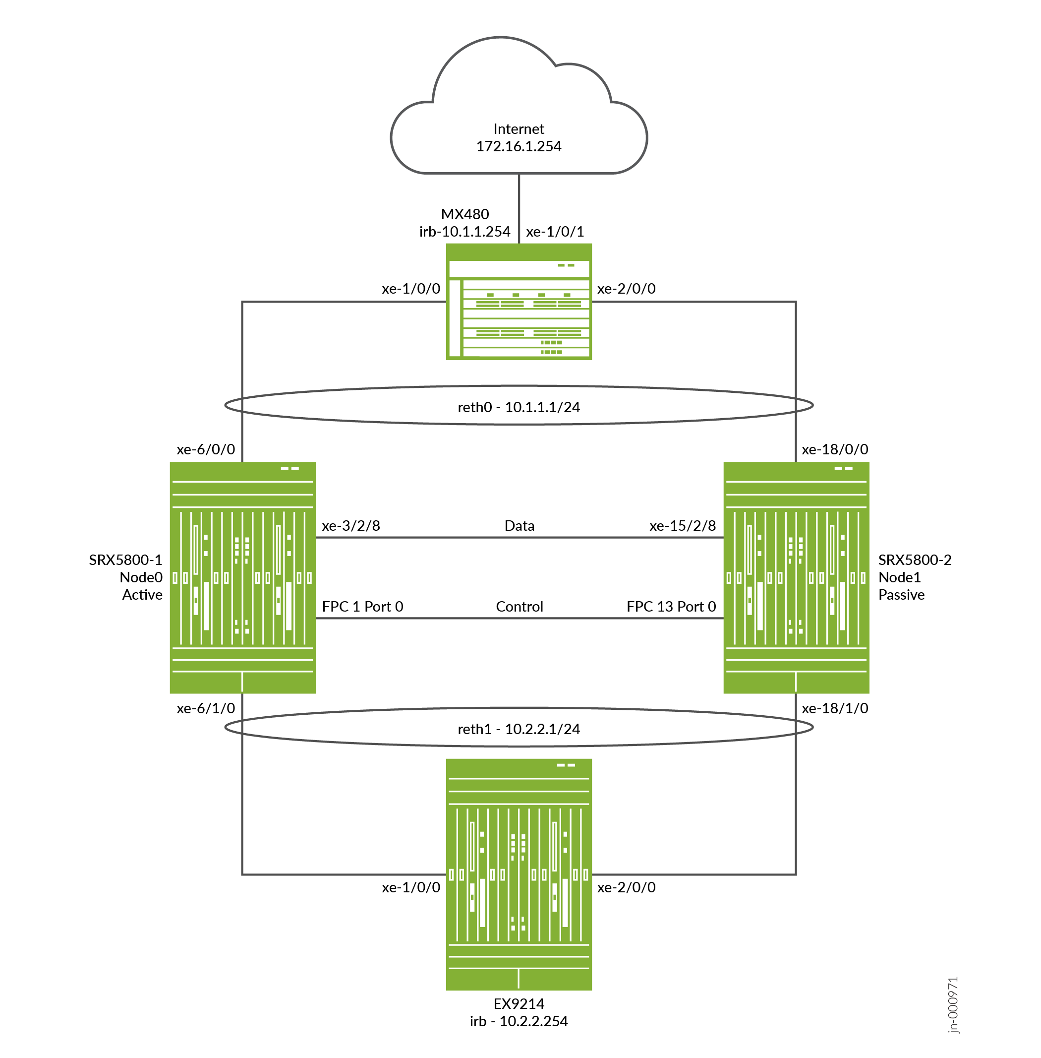
同じハードウェア構成のSRX5800ファイアウォールが2台必要で、エンドツーエンドのデータトラフィックを送信するためには、オプションで1台のMX480 エッジルーターと1台のEX9214イーサネットスイッチが必要です。
-
2 つのデバイスを物理的に接続し(ファブリックと制御ポートをバックツーバックで接続)、それらが同じモデルであることを確認します。
-
クラスタを形成する前に、各デバイスに制御ポートを設定し、各デバイスにクラスタIDとノードIDを割り当てて、再起動する必要があります。システムが起動すると、両方のノードがクラスタとして立ち上がります。
SRX5400、SRX5600、およびSRX5800ファイアウォールには、制御ポートの設定が必要です。
これでデバイスはペアになりました。これ以降、ノード メンバー間でクラスタの設定が同期され、2台のデバイスは1台のデバイスとして機能します。
概要
この例では、SRXシリーズファイアウォールで基本的なアクティブ/パッシブシャーシクラスタリングを設定する方法を説明します。基本的なアクティブ/パッシブの例は、最も一般的なタイプのシャーシ クラスタです。
基本的なアクティブ/パッシブ シャーシ クラスタは、2 つのデバイスで構成されています。
-
1台のデバイスが、シャーシクラスターの制御を維持しながら、ルーティング、ファイアウォール、NAT、VPN、セキュリティサービスをアクティブに提供します。
-
もう一方のデバイスは、アクティブデバイスが非アクティブになった場合に備えて、クラスタフェイルオーバー機能のためにその状態を受動的に維持します。
このSRX5800ファイアウォールのアクティブ/パッシブモードの例では、NAT、セキュリティポリシー、VPNの設定方法などのその他の設定については詳細に説明していません。これらは、基本的にスタンドアロン構成の場合と同じです。ただし、シャーシ クラスタ設定でプロキシ ARPを実行する場合は、RETH インターフェイスが論理設定を保持するため、メンバー インターフェイスではなく reth インターフェイスにプロキシ ARP設定を適用する必要があります。 NAT 用プロキシ ARP の設定(CLI 手順)を参照してください。SRX5800ファイアウォールでVLANとトランクされたインターフェイスを使用して、個別の論理インターフェイス構成を構成することもできます。これらの構成は、VLAN とトランク インターフェイスを使用するスタンドアロン実装と類似しています。
図 2 は、この例で使用されるトポロジーを示しています。
構成
制御ポートの設定とクラスタ モードの有効化
CLIクイック構成
この例を迅速に設定するには、以下のコマンドをコピーして、テキスト ファイルに貼り付け、改行を削除し、ネットワーク設定に一致させる必要がある詳細情報を変更し、コマンドを [edit] 階層レベルで CLI にコピー アンド ペーストして、設定モードから commit を入力します。
{primary:node0}について
[edit]
set groups node0 system host-name hostA


                  set groups node0 system backup-router 10.52.63.254


                  set groups node0 system backup-router destination 10.0.0.0/8


                  set groups node0 interfaces fxp0 unit 0 family inet address 10.52.43.57/19


                  set groups node1 system host-name hostB


                  set groups node1 system backup-router 10.52.63.254


                  set groups node1 system backup-router destination 10.0.0.0/8


                  set groups node1 interfaces fxp0 unit 0 family inet address 10.52.52.27/19


                  set apply-groups “${node}”


                  set chassis cluster control-ports fpc 1 port 0


                  set chassis cluster control-ports fpc 13 port 0


                  set chassis cluster control-link-recovery


                  set chassis cluster reth-count 2


                  set chassis cluster redundancy-group 0 node 0 priority 254


                  set chassis cluster redundancy-group 0 node 1 priority 1


                  set chassis cluster redundancy-group 1 node 0 priority 254


                  set chassis cluster redundancy-group 1 node 1 priority 1


                  set chassis cluster redundancy-group 1 interface-monitor xe-6/0/0 weight 255


                  set chassis cluster redundancy-group 1 interface-monitor xe-18/0/0 weight 255


                  set chassis cluster redundancy-group 1 interface-monitor xe-6/1/0 weight 255


                  set chassis cluster redundancy-group 1 interface-monitor xe-18/1/0 weight 255


                  set security policies from-zone trust to-zone untrust policy allow match source-address any


                  set security policies from-zone trust to-zone untrust policy allow match destination-address any


                  set security policies from-zone trust to-zone untrust policy allow match application any


                  set security policies from-zone trust to-zone untrust policy allow then permit


                  set security policies from-zone untrust to-zone trust policy allow match source-address any


                  set security policies from-zone untrust to-zone trust policy allow match destination-address any


                  set security policies from-zone untrust to-zone trust policy allow match application any


                  set security policies from-zone untrust to-zone trust policy allow then permit


                  set security zones security-zone trust host-inbound-traffic system-services ping


                  set security zones security-zone trust interfaces reth1.50


                  set security zones security-zone untrust host-inbound-traffic system-services ping


                  set security zones security-zone untrust interfaces reth0.51


                  set interfaces xe-6/1/0 gigether-options redundant-parent reth1


                  set interfaces xe-6/0/0 gigether-options redundant-parent reth0


                  set interfaces xe-18/1/0 gigether-options redundant-parent reth1


                  set interfaces xe-18/0/0 gigether-options redundant-parent reth0


                  set interfaces fab0 fabric-options member-interfaces xe-3/2/8


                  set interfaces fab1 fabric-options member-interfaces xe-15/2/8


                  set interfaces reth0 vlan-tagging


                  set interfaces reth0 redundant-ether-options redundancy-group 1


                  set interfaces reth0 unit 51 vlan-id 51


                  set interfaces reth0 unit 51 family inet address 10.1.1.1/24


                  set interfaces reth1 vlan-tagging


                  set interfaces reth1 redundant-ether-options redundancy-group 1


                  set interfaces reth1 unit 50 vlan-id 50


                  set interfaces reth1 unit 50 family inet address 10.2.2.1/24


                  set routing-options static route 10.0.0.0/8 next-hop 10.52.63.254


                  set routing-options static route 172.16.1.0/24 next-hop 10.1.1.254
(オプション)EX9214 コア スイッチを素早く構成するには、以下のコマンドをコピーしてテキスト ファイルに貼り付け、改行を削除し、ネットワーク構成に合わせて必要な詳細を変更し、コマンドを [edit] 階層レベルで CLI にコピー アンド ペーストして、構成モードから commit を入力します。
EXデバイスの場合
[edit]
set interfaces xe-1/0/0 unit 0 family ethernet-switching interface-mode trunk


                  set interfaces xe-1/0/0 unit 0 family ethernet-switching vlan members v50


                  set interfaces xe-2/0/0 unit 0 family ethernet-switching interface-mode trunk


                  set interfaces xe-2/0/0 unit 0 family ethernet-switching vlan members v50


                  set interfaces irb unit 50 family inet address 10.2.2.254/24


                  set routing-options static route 10.1.1.0/24 next-hop 10.2.2.1


                  set routing-options static route 172.16.1.0/24 next-hop 10.2.2.1


                  set vlans v50 vlan-id 50


                  set vlans v50 l3-interface irb.50
(オプション)MX480エッジルーターを迅速に設定するには、以下のコマンドをコピーしてテキストファイルに貼り付け、改行を削除し、ネットワーク設定に合わせて必要な詳細を変更し、コマンドを [edit] 階層レベルでCLIにコピーアンドペーストして、設定モードから commit を入力します。
MX デバイスの場合
[edit]
set interfaces xe-1/0/0 encapsulation ethernet-bridge


                  set interfaces xe-1/0/0 unit 0 family bridge interface-mode trunk


                  set interfaces xe-1/0/0 unit 0 family bridge vlan-id 51


                  set interfaces xe-1/0/1 unit 0 family inet address 172.16.1.1/24


                  set interfaces xe-2/0/0 encapsulation ethernet-bridge


                  set interfaces xe-2/0/0 unit 0 family bridge interface-mode trunk


                  set interfaces xe-2/0/0 unit 0 family bridge vlan-id 51


                  set interfaces irb unit 0 family inet address 10.1.1.254/24


                  set routing-options static route 10.2.2.0/24 next-hop 10.1.1.1


                  set bridge-domains v51 domain-type bridge


                  set bridge-domains v51 vlan-id 51


                  set bridge-domains v51 routing-interface irb.0
手順
次の例では、設定階層のいくつかのレベルに移動する必要があります。
SRXシリーズファイアウォールでシャーシクラスターを設定するには、次の手順に従います。
クラスタモードでは、 commit コマンドを実行すると、ノード間の制御リンクを介して設定が同期されます。コマンドが設定されたデバイスに関係なく、すべてのコマンドは両方のノードに適用されます。
-
SRX5000ファイアウォールシャーシクラスタ設定は、単一の共通設定内に含まれているため、設定の一部の要素を特定のメンバーのみに割り当てるには、グループと呼ばれるJunos OSノード固有の設定方法を使用する必要があります。
set apply-groups ${node}コマンドは、ノード変数を使用して、ノードにグループを適用する方法を定義します。各ノードはその番号を認識し、それに応じて設定を受け入れます。また、SRX5000ファイアウォールのfxp0インターフェイス上で、クラスタの個々のコントロールプレーンに個別のIPアドレスを使用して帯域外管理を設定する必要があります。バックアップ ルーターの宛先アドレスを x.x.x.0/0 として設定することはできません。
user@hostA# set groups node0 system host-name hostA user@hostA# set groups node0 system backup-router 10.52.63.254 user@hostA# set groups node0 system backup-router destination 10.0.0.0/8 user@hostA# set groups node0 interfaces fxp0 unit 0 family inet address 10.52.43.57/19user@hostB# set groups node1 system host-name hostB user@hostB# set groups node1 system backup-router 10.52.63.254 user@hostB# set groups node1 system backup-router destination 10.0.0.0/8 user@hostB# set groups node1 interfaces fxp0 unit 0 family inet address 10.52.52.27/19上記のグループ node0 と node1 の設定はコミットされますが、適用されません。デバイスがクラスタ内で立ち上がると、これらのコマンドは
set apply-groups “${node}”を使用して適用されます。 -
以下のコマンドを使用して、プライマリであるノード 0 を設定します。ノード 1 は、ノード構成がコミットされるまで到達できません。ノード 0 は、制御ポートを介してノード 1 に設定を自動的に同期するため、ノード 1 を明示的に設定する必要はありません。
user@hostA# set apply-groups “${node}” -
各デバイスに制御ポートを設定し、設定をコミットします。
設定に従って、両方のノードのSPCカード間に物理制御リンク接続があることを確認します。
制御ポートはシャーシ内のSPC位置に基づいて取得され、オフセット値はプラットフォームに基づきます。以下の例では、SPC は収益スロット 1 に存在し、SRX5800 のオフセットが 12 であるため、制御ポートは 1, 13 です。特定のプラットフォームのオフセット値を表示するには、シェル モードで
“jwhoami -c”コマンドを使用します。両方のデバイスで次のコマンドを入力する必要があります。例えば:-
ノード0:
user@hostA# set chassis cluster control-ports fpc 1 port 0 user@hostA# set chassis cluster control-ports fpc 13 port 0 user@hostA# commit -
ノード1:
user@hostB# set chassis cluster control-ports fpc 1 port 0
user@hostB# set chassis cluster control-ports fpc 13 port 0
user@hostB# commit
-
-
2台のデバイスをクラスタ モードに設定します。クラスタIDとノードIDを設定した後、クラスタモードに入るには再起動が必要です。CLI コマンドラインに
rebootパラメータを含めることで、システムを自動的に起動させることができます。両方のデバイスで動作モードコマンドを入力する必要があります。例えば:-
ノード0:
user@hostA> set chassis cluster cluster-id 1 node 0 reboot -
ノード1:
user@hostB> set chassis cluster cluster-id 1 node 1 reboot
クラスタIDはクラスタ内の両方のデバイスで同じである必要がありますが、一方のデバイスはノード0でもう一方のデバイスはノード1であるため、ノードIDは異なっている必要があります。クラスタ ID の範囲は 1 から 255 です。クラスタ ID を 0 に設定することは、クラスタを無効にすることと同じです。ただし、
set chassis cluster disableを使用してクラスタからノードを解除することをお勧めします。 -
-
シャーシクラスタリングの冗長グループを設定します。各ノードは冗長性グループ内にインターフェイスを持ち、インターフェイスはアクティブ冗長グループ内でアクティブになります(1つの冗長性グループに複数のアクティブインターフェイスが存在できます)。冗長グループ0はコントロールプレーンを制御し、冗長グループ1+はデータプレーンを制御し、データプレーンポートを含みます。このアクティブ/パッシブ モードの例では、一度に 1 つのシャーシ クラスタ メンバーしかアクティブにならないため、冗長グループ 0 と 1 のみを定義する必要があります。冗長性のグループの他に、以下も定義する必要があります。
-
冗長イーサネットグループ—システムが適切なリソースを割り当てられるように、デバイス上でアクティブになる冗長イーサネットインターフェイス(メンバーリンク)の数を設定します。
-
コントロールプレーンとデータプレーンの優先度:コントロールプレーンの優先度(シャーシクラスターでは優先度の高い優先度が優先される)と、データプレーンに対してアクティブにすることを優先するデバイスを定義します。
-
アクティブ/パッシブモードまたはアクティブ/アクティブモードでは、コントロールプレーン(冗長グループ0)をデータプレーン(冗長グループ1+およびグループ)シャーシとは異なるシャーシ上でアクティブにすることができます。ただし、この例では、同じシャーシメンバー上でコントロールプレーンとデータプレーンの両方をアクティブにすることを推奨します。トラフィックがファブリックリンクを通過して別のメンバーノードに移動すると、遅延が発生します(zラインモードトラフィック)。
-
SRXシリーズファイアウォール(SRX5000シリーズ)では、IPSec VPNはZモードのアクティブ/アクティブシャーシクラスター設定(つまり、複数のRG1+冗長グループがある場合)ではサポートされません。
-
user@hostA# set chassis cluster reth-count 2 user@hostA# set chassis cluster redundancy-group 1 node 0 priority 254 user@hostA# set chassis cluster redundancy-group 1 node 1 priority 1 user@hostA# set chassis cluster redundancy-group 0 node 0 priority 254 user@hostA# set chassis cluster redundancy-group 0 node 1 priority 1 -
-
アクティブ/パッシブモードでRTOを渡すために使用されるクラスターのファブリック(データ)ポートを設定します。この例では、revenue ポートの 1 つを使用します。互いに接続するために、各シャーシに 1 つずつ、合計 2 つのファブリック インターフェイスを定義します。
データプレーンのフェイルオーバーが発生した場合、もう一方のシャーシクラスタメンバーがシームレスに接続を引き継ぐことができるように、プラットフォーム上のデータインターフェイスを設定します。新しいアクティブノードへのシームレスな移行は、データプレーンのフェイルオーバーで行われます。コントロールプレーンのフェイルオーバーの場合、すべてのデーモンが新しいノードで再起動されるため、ピア(ospf、bgp)とのネイバーシップが失われないようにグレースフルリスタートが可能になります。これにより、パケットロスが発生することなく、新しいノードにシームレスに移行できます。
以下の項目を定義する必要があります。
-
reth インターフェイスに対するメンバー インターフェイスのメンバーシップ情報を定義します。
-
rethインターフェイスがどの冗長性グループに属しているかを定義します。このアクティブ/パッシブの例では、常に 1 です。
-
インターフェイスのIPアドレスなどのrethインターフェイス情報を定義します。
{primary:node0}[edit]user@hostA# set interfaces xe-6/1/0 gigether-options redundant-parent reth1 user@hostA# set interfaces xe-6/0/0 gigether-options redundant-parent reth0 user@hostA# set interfaces xe-18/1/0 gigether-options redundant-parent reth1 user@hostA# set interfaces xe-18/0/0 gigether-options redundant-parent reth0 user@hostA# set interfaces reth0 vlan-tagging user@hostA# set interfaces reth0 redundant-ether-options redundancy-group 1 user@hostA# set interfaces reth0 unit 51 vlan-id 51 user@hostA# set interfaces reth0 unit 51 family inet address 10.1.1.1/24 user@hostA# set interfaces reth1 vlan-tagging user@hostA# set interfaces reth1 redundant-ether-options redundancy-group 1 user@hostA# set interfaces reth1 unit 50 vlan-id 50 user@hostA# set interfaces reth1 unit 50 family inet address 10.2.2.1/24 user@hostA# set interfaces fab0 fabric-options member-interfaces xe-3/2/8 user@hostA# set interfaces fab1 fabric-options member-interfaces xe-15/2/8 -
-
(オプション)障害発生時のシャーシ クラスタの動作を設定します。SRX5800 ファイアウォールの場合、フェールオーバーのしきい値は 255 に設定されます。重みを変更して、シャーシのフェールオーバーへの影響を判断できます。また、制御リンクの回復も設定する必要があります。このリカバリにより、制御リンクに障害が発生した場合にセカンダリ ノードが自動的に再起動され、その後オンラインに戻ります。ノード0で以下のコマンドを入力します。
{primary:node0}[edit]user@hostA# set chassis cluster redundancy-group 1 interface-monitor xe-6/0/0 weight 255 user@hostA# set chassis cluster redundancy-group 1 interface-monitor xe-6/1/0 weight 255 user@hostA# set chassis cluster redundancy-group 1 interface-monitor xe-18/0/0 weight 255 user@hostA# set chassis cluster redundancy-group 1 interface-monitor xe-18/1/0 weight 255 user@hostA# set chassis cluster control-link-recoveryこのステップで、SRX5800ファイアウォールのアクティブ/パッシブモードの例のシャーシクラスタ設定部分を完了します。この手順の残りの部分では、ゾーン、仮想ルーター、ルーティング、EX9214コアスイッチ、MX480エッジルーターを設定して導入シナリオを完了する方法を説明します。
-
(オプション)rethインターフェイスを設定し、適切なゾーンと仮想ルーターに接続します。この例では、reth0およびreth1インターフェイスをデフォルトの仮想ルーターinet.0に残します。これは追加の設定を必要としません。
{primary:node0}[edit]user@hostA# set security zones security-zone trust host-inbound-traffic system-services ping user@hostA# set security zones security-zone trust interfaces reth1.50 user@hostA# set security zones security-zone untrust host-inbound-traffic system-services ping user@hostA# set security zones security-zone untrust interfaces reth0.51 -
trustゾーンからuntrustゾーンへのトラフィックを許可するセキュリティポリシーを作成します。
user@hostA# set security policies from-zone trust to-zone untrust policy allow match source-address any user@hostA# set security policies from-zone trust to-zone untrust policy allow match destination-address any user@hostA# set security policies from-zone trust to-zone untrust policy allow match application any user@hostA# set security policies from-zone trust to-zone untrust policy allow then permit user@hostA# set security policies from-zone untrust to-zone trust policy allow match source-address any user@hostA# set security policies from-zone untrust to-zone trust policy allow match destination-address any user@hostA# set security policies from-zone untrust to-zone trust policy allow match application any user@hostA# set security policies from-zone untrust to-zone trust policy allow then permit -
(オプション)EX9214イーサネットスイッチでは、以下のコマンドは、SRX5800ファイアウォールのアクティブ/パッシブモードの例に関連する適用可能な構成の概要のみを提供します。特に顕著なのは、VLAN、ルーティング、およびインターフェイス構成です。
[edit]user@switch# set interfaces xe-1/0/0 unit 0 family ethernet-switching interface-mode trunk user@switch# set interfaces xe-1/0/0 unit 0 family ethernet-switching vlan members v50 user@switch# set interfaces xe-2/0/0 unit 0 family ethernet-switching interface-mode trunk user@switch# set interfaces xe-2/0/0 unit 0 family ethernet-switching vlan members v50 user@switch# set interfaces irb unit 50 family inet address 10.2.2.254/24 user@switch# set routing-options static route 10.1.1.0/24 next-hop 10.2.2.1 user@switch# set routing-options static route 172.16.1.0/24 next-hop 10.2.2.1 user@switch# set vlans v50 vlan-id 50 user@switch# set vlans v50 l3-interface irb.50 -
(オプション)MX480エッジルーターの場合、以下のコマンドは、SRX5800ファイアウォールのアクティブ/パッシブモードの例に関連する適用可能な設定の概要のみを提供します。特に、スイッチ上の仮想スイッチ インスタンス内で IRB インターフェイスを使用する必要があります。
[edit]user@router# set interfaces xe-1/0/0 encapsulation ethernet-bridge user@router# set interfaces xe-1/0/0 unit 0 family bridge interface-mode trunk user@router# set interfaces xe-1/0/0 unit 0 family bridge vlan-id 51 user@router# set interfaces xe-1/0/1 unit 0 family inet address 172.16.1.1/24 user@router# set interfaces xe-2/0/0 encapsulation ethernet-bridge user@router# set interfaces xe-2/0/0 unit 0 family bridge interface-mode trunk user@router# set interfaces xe-2/0/0 unit 0 family bridge vlan-id 51 user@router# set interfaces irb unit 0 family inet address 10.1.1.254/24 user@router# set routing-options static route 10.2.2.0/24 next-hop 10.1.1.1 user@router# set bridge-domains v51 domain-type bridge user@router# set bridge-domains v51 vlan-id 51 user@router# set bridge-domains v51 routing-interface irb.0
検証
設定が正常に機能していることを確認します。
- シャーシ クラスタ ステータスの確認
- シャーシ クラスタ インターフェイスの確認
- シャーシ クラスタ統計情報の確認
- シャーシ クラスタ コントロール プレーン統計情報の確認
- シャーシ クラスタ データ プレーン統計情報の確認
- EXデバイスからのpingの確認
- シャーシ クラスタ冗長グループ ステータスの確認
- ログを使用したトラブルシューティング
シャーシ クラスタ ステータスの確認
目的
シャーシ クラスタ ステータス、フェイルオーバー ステータス、冗長グループ情報を検証します。
アクション
動作モードから show chassis cluster status コマンドを入力します。
{primary:node0}
user@hostA> show chassis cluster status
Monitor Failure codes:
    CS  Cold Sync monitoring        FL  Fabric Connection monitoring
    GR  GRES monitoring             HW  Hardware monitoring
    IF  Interface monitoring        IP  IP monitoring
    LB  Loopback monitoring         MB  Mbuf monitoring
    NH  Nexthop monitoring          NP  NPC monitoring
    SP  SPU monitoring              SM  Schedule monitoring
    CF  Config Sync monitoring      RE  Relinquish monitoring
    IS  IRQ storm

Cluster ID: 1
Node   Priority Status               Preempt Manual   Monitor-failures

Redundancy group: 0 , Failover count: 1
node0  254      primary              no      no       None
node1  1        secondary            no      no       None

Redundancy group: 1 , Failover count: 1
node0  254      primary              no      no       None
node1  1        secondary            no      no       None
シャーシ クラスタ インターフェイスの確認
目的
シャーシ クラスタ インターフェイスに関する情報を検証します。
アクション
動作モードから show chassis cluster interfaces コマンドを入力します。
{primary:node0}
user@hostA> show chassis cluster interfaces
Control link status: Up

Control interfaces:
    Index   Interface   Monitored-Status   Internal-SA   Security
    0       em0         Up                 Disabled      Disabled

Fabric link status: Up

Fabric interfaces:
    Name    Child-interface    Status                    Security
                               (Physical/Monitored)
    fab0    xe-3/2/8           Up   / Up                 Disabled
    fab0
    fab1    xe-15/2/8           Up   / Up                 Disabled
    fab1

Redundant-ethernet Information:
    Name         Status      Redundancy-group
    reth0        Up          1
    reth1        Up          1

Redundant-pseudo-interface Information:
    Name         Status      Redundancy-group
    lo0          Up          0

Interface Monitoring:
    Interface         Weight    Status                    Redundancy-group
                                (Physical/Monitored)
    xe-18/1/0          255       Up  /  Up                 1
    xe-6/1/0          255       Up  /  Up                 1
    xe-18/0/0          255       Up  /  Up                 1
    xe-6/0/0          255       Up  /  Up                 1
シャーシ クラスタ統計情報の確認
目的
シャーシ クラスタ サービスおよび制御リンク統計情報(送受信したハートビート)、ファブリック リンク統計情報(送受信したプローブ)、およびサービスで送受信された RTO 数に関する情報を検証します。
アクション
動作モードから show chassis cluster statistics コマンドを入力します。
{primary:node0}
user@hostA> show chassis cluster statistics

Control link statistics:
    Control link 0:
        Heartbeat packets sent: 229414
        Heartbeat packets received: 229385
        Heartbeat packet errors: 0
Fabric link statistics:
    Child link 0
        Probes sent: 459691
        Probes received: 459679
    Child link 1
        Probes sent: 0
        Probes received: 0
Services Synchronized:
    Service name                              RTOs sent    RTOs received
    Translation context                       0            0
    Incoming NAT                              0            0
    Resource manager                          0            0
    DS-LITE create                            0            0
    Session create                            0            0
    IPv6 session create                       0            0
    IPv4/6 session RTO ACK                    0            0
    Session close                             0            0
    IPv6 session close                        0            0
    Session change                            0            0
    IPv6 session change                       0            0
    ALG Support Library                       0            0
    Gate create                               0            0
    Session ageout refresh requests           0            0
    IPv6 session ageout refresh requests      0            0
    Session ageout refresh replies            0            0
    IPv6 session ageout refresh replies       0            0
    IPSec VPN                                 0            0
    Firewall user authentication              0            0
    MGCP ALG                                  0            0
    H323 ALG                                  0            0
    SIP ALG                                   0            0
    SCCP ALG                                  0            0
    PPTP ALG                                  0            0
    JSF PPTP ALG                              0            0
    RPC ALG                                   0            0
    RTSP ALG                                  0            0
    RAS ALG                                   0            0
    MAC address learning                      0            0
    GPRS GTP                                  0            0
    GPRS SCTP                                 0            0
    GPRS FRAMEWORK                            0            0
    JSF RTSP ALG                              0            0
    JSF SUNRPC MAP                            0            0
    JSF MSRPC MAP                             0            0
    DS-LITE delete                            0            0
    JSF SLB                                   0            0
    APPID                                     0            0
    JSF MGCP MAP                              0            0
    JSF H323 ALG                              0            0
    JSF RAS ALG                               0            0
    JSF SCCP MAP                              0            0
    JSF SIP MAP                               0            0
    PST_NAT_CREATE                            0            0
    PST_NAT_CLOSE                             0            0
    PST_NAT_UPDATE                            0            0
    JSF TCP STACK                             0            0
    JSF IKE ALG                               0            0

Packet stats                              Pkts sent    Pkts received
    ICD Data                                  0            0
シャーシ クラスタ コントロール プレーン統計情報の確認
目的
シャーシ クラスタ コントロール プレーン統計情報(送受信したハートビート)とファブリック リンク統計情報(送受信したプローブ)に関する情報を検証します。
アクション
動作モードから show chassis cluster control-plane statistics コマンドを入力します。
{primary:node0}
user@hostA> show chassis cluster control-plane statistics
Control link statistics:
    Control link 0:
        Heartbeat packets sent: 229474
        Heartbeat packets received: 229445
        Heartbeat packet errors: 0
Fabric link statistics:
    Child link 0
        Probes sent: 459809
        Probes received: 459797
    Child link 1
        Probes sent: 0
        Probes received: 0
シャーシ クラスタ データ プレーン統計情報の確認
目的
サービスで送受信されたRTO数に関する情報を確認します。
アクション
動作モードから show chassis cluster data-plane statistics コマンドを入力します。
{primary:node0}
user@hostA> show chassis cluster data-plane statistics
Services Synchronized:
    Service name                              RTOs sent    RTOs received
    Translation context                       0            0
    Incoming NAT                              0            0
    Resource manager                          0            0
    DS-LITE create                            0            0
    Session create                            0            0
    IPv6 session create                       0            0
    Session close                             0            0
    IPv6 session close                        0            0
    Session change                            0            0
    IPv6 session change                       0            0
    ALG Support Library                       0            0
    Gate create                               0            0
    Session ageout refresh requests           0            0
    IPv6 session ageout refresh requests      0            0
    Session ageout refresh replies            0            0
    IPv6 session ageout refresh replies       0            0
    IPSec VPN                                 0            0
    Firewall user authentication              0            0
    MGCP ALG                                  0            0
    H323 ALG                                  0            0
    SIP ALG                                   0            0
    SCCP ALG                                  0            0
    PPTP ALG                                  0            0
    JSF PPTP ALG                              0            0
    RPC ALG                                   0            0
    RTSP ALG                                  0            0
    RAS ALG                                   0            0
    MAC address learning                      0            0
    GPRS GTP                                  0            0
    GPRS SCTP                                 0            0
    GPRS FRAMEWORK                            0            0
    JSF RTSP ALG                              0            0
    JSF SUNRPC MAP                            0            0
    JSF MSRPC MAP                             0            0
    DS-LITE delete                            0            0
    JSF SLB                                   0            0
    APPID                                     0            0
    JSF MGCP MAP                              0            0
    JSF H323 ALG                              0            0
    JSF RAS ALG                               0            0
    JSF SCCP MAP                              0            0
    JSF SIP MAP                               0            0
    PST_NAT_CREATE                            0            0
    PST_NAT_CLOSE                             0            0
    PST_NAT_UPDATE                            0            0
    JSF TCP STACK                             0            0
    JSF IKE ALG                               0            0
EXデバイスからのpingの確認
目的
EXデバイスから接続状態を確認します。
アクション
動作モードから ping 172.16.1.254 count 2 コマンドを入力します。
user@EX9214> ping 172.16.1.254 count 2
PING 172.16.1.254 (172.16.1.254): 56 data bytes
64 bytes from 172.16.1.254: icmp_seq=0 ttl=62 time=4.599 ms
64 bytes from 172.16.1.254: icmp_seq=1 ttl=62 time=3.192 ms

--- 172.16.1.254 ping statistics ---
2 packets transmitted, 2 packets received, 0% packet loss
round-trip min/avg/max/stddev = 3.192/3.896/4.599/0.704 ms
シャーシ クラスタ冗長グループ ステータスの確認
目的
クラスタ内の両ノードの状態と優先度、プライマリ ノードの事前対応の有無または手動フェイルオーバーの有無に関する情報を検証します。
アクション
動作モードから chassis cluster status redundancy-group コマンドを入力します。
{primary:node0}
user@hostA> show chassis cluster status redundancy-group 1
Monitor Failure codes:
    CS  Cold Sync monitoring        FL  Fabric Connection monitoring
    GR  GRES monitoring             HW  Hardware monitoring
    IF  Interface monitoring        IP  IP monitoring
    LB  Loopback monitoring         MB  Mbuf monitoring
    NH  Nexthop monitoring          NP  NPC monitoring
    SP  SPU monitoring              SM  Schedule monitoring
    CF  Config Sync monitoring      RE  Relinquish monitoring

Cluster ID: 1
Node   Priority Status         Preempt Manual   Monitor-failures

Redundancy group: 1 , Failover count: 1
node0  254      primary        no      no       None
node1  1        secondary      no      no       None
例:アクティブ/パッシブ シャーシ クラスタ ペア(SRX1500またはSRX1600)の設定
この例では、SRX1500またはSRX1600デバイスに対してアクティブ/パッシブ シャーシ クラスタリングを設定する方法を示しています。
必要条件
開始する前に、以下を実行します。
2 組のデバイスを物理的に接続し、それらが同じモデルであることを確認します。
あるデバイス上のギガビットイーサネットインターフェイスを、別のデバイス上の別のギガビットイーサネットインターフェイスに接続して、ファブリックリンクを作成します。
2台のSRX1500デバイスの制御ポートを接続して、制御リンクを作成します。
コンソール ポートを使用して、デバイスの 1 つに接続します。(これは、クラスターを形成するノードです。をクリックし、クラスタ ID とノード番号を設定します。
user@host> set chassis cluster cluster-id 1 node 0 reboot
コンソール ポートを使用して他のデバイスに接続し、クラスタ ID とノード番号を設定します。
user@host> set chassis cluster cluster-id 1 node 1 reboot
概要
この例では、クラスタ内の 1 つのデバイスがすべてのトラフィックのルーティングに使用され、他のデバイスは障害発生時にのみ使用されます。( 図 3 を参照)。障害が発生すると、バックアップ デバイスがプライマリになり、すべての転送を制御します。
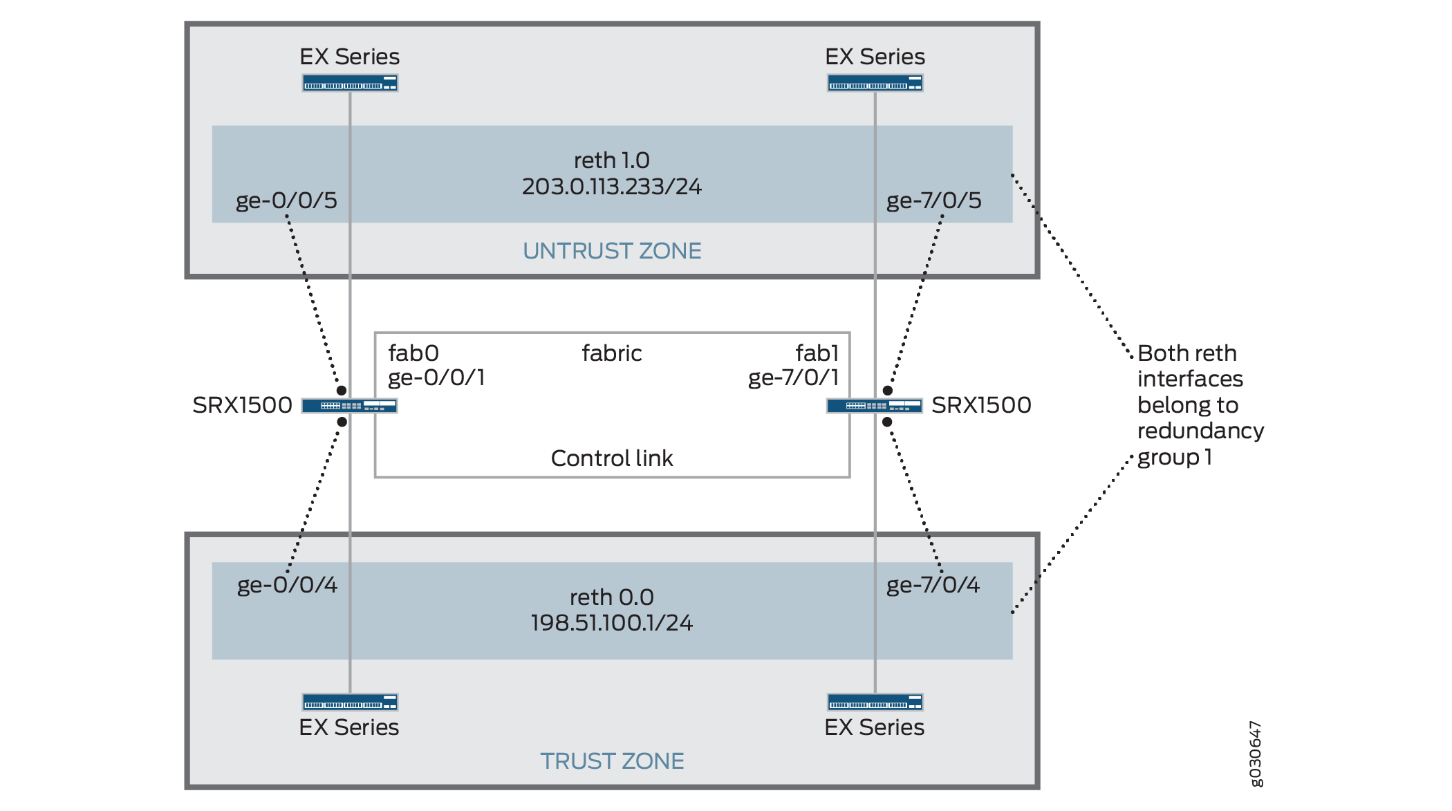
すべて同じ冗長グループに割り当てられる冗長イーサネットインターフェイス(reth)を設定することで、アクティブ/パッシブシャーシクラスターを作成できます。この構成では、常にクラスタ内の 1 つのノードのみがトラフィックを転送するため、ファブリック リンク上のトラフィックが最小限に抑えられます。
この例では、グループ( apply-groups コマンドで設定を適用)とシャーシ クラスタ情報を設定します。次に、セキュリティゾーンとセキュリティポリシーを設定します。 表 1 から 表 4 を参照してください。
特徴 |
名前 |
設定パラメータ |
|---|---|---|
グループ |
ノード0 |
|
ノード1 |
|
特徴 |
名前 |
設定パラメータ |
|---|---|---|
ファブリックリンク |
ファブ0 |
インターフェイス:ge-0/0/1 |
ファブ1 |
インターフェイス:ge-7/0/1 |
|
ハートビート間隔 |
– |
1000 |
ハートビートしきい値 |
– |
3 |
リダンダンシーグループ |
0 |
|
1 |
|
|
インターフェイス監視
|
||
冗長イーサネットインターフェイスの数 |
– |
2 |
インターフェイス |
ge-0/0/4 |
冗長な親: reth0 |
ge-7/0/4 |
冗長な親: reth0 |
|
ge-0/0/5 |
冗長な親: reth1 |
|
ge-7/0/5 |
冗長な親: reth1 |
|
reth0さん |
冗長グループ:1 |
|
|
||
reth1 (レス1) |
冗長グループ:1 |
|
|
名前 |
設定パラメータ |
|---|---|
信託 |
reth1.0インターフェイスは、このゾーンにバインドされています。 |
信頼できない |
reth0.0インターフェイスは、このゾーンにバインドされています。 |
目的 |
名前 |
設定パラメータ |
|---|---|---|
このセキュリティ ポリシーは、trustゾーンからuntrustゾーンへのトラフィックを許可します。 |
任意 |
|
構成
プロシージャ
CLIクイック構成
この例を迅速に設定するには、以下のコマンドをコピーして、テキスト ファイルに貼り付け、改行を削除し、ネットワーク設定に一致させる必要がある詳細情報を変更し、コマンドを [edit] 階層レベルで CLI にコピー アンド ペーストして、設定モードから commit を入力します。
[edit]
set groups node0 system host-name srx1500-A
set groups node0 interfaces fxp0 unit 0 family inet address 192.0.2.110/24
set groups node1 system host-name srx1500-B
set groups node1 interfaces fxp0 unit 0 family inet address 192.0.2.111/24
set apply-groups “${node}”
set interfaces fab0 fabric-options member-interfaces ge-0/0/1
set interfaces fab1 fabric-options member-interfaces ge-7/0/1
set chassis cluster heartbeat-interval 1000
set chassis cluster heartbeat-threshold 3
set chassis cluster redundancy-group 0 node 0 priority 100
set chassis cluster redundancy-group 0 node 1 priority 1
set chassis cluster redundancy-group 1 node 0 priority 100
set chassis cluster redundancy-group 1 node 1 priority 1
set chassis cluster redundancy-group 1 interface-monitor ge-0/0/4 weight 255
set chassis cluster redundancy-group 1 interface-monitor ge-7/0/4 weight 255
set chassis cluster redundancy-group 1 interface-monitor ge-0/0/5 weight 255
set chassis cluster redundancy-group 1 interface-monitor ge-7/0/5 weight 255
set chassis cluster reth-count 2
set interfaces ge-0/0/5 gigether-options redundant-parent reth1
set interfaces ge-7/0/5 gigether-options redundant-parent reth1
set interfaces ge-0/0/4 gigether-options redundant-parent reth0
set interfaces ge-7/0/4 gigether-options redundant-parent reth0
set interfaces reth0 redundant-ether-options redundancy-group 1
set interfaces reth0 unit 0 family inet address 198.51.100.1/24
set interfaces reth1 redundant-ether-options redundancy-group 1
set interfaces reth1 unit 0 family inet address 203.0.113.233/24
set security zones security-zone untrust interfaces reth1.0
set security zones security-zone trust interfaces reth0.0
set security policies from-zone trust to-zone untrust policy ANY match source-address any
set security policies from-zone trust to-zone untrust policy ANY match destination-address any
set security policies from-zone trust to-zone untrust policy ANY match application any
set security policies from-zone trust to-zone untrust policy ANY then permit
手順
アクティブ/パッシブ シャーシ クラスタを設定するには、次の手順に従います。
管理インターフェイスを設定します。
{primary:node0}[edit]
user@host# set groups node0 system host-name srx1500-A
user@host# set groups node0 interfaces fxp0 unit 0 family inet address 192.0.2.110/24
user@host# set groups node1 system host-name srx1500-B
user@host# set groups node1 interfaces fxp0 unit 0 family inet address 192.0.2.111/24
user@host# set apply-groups “${node}”
ファブリックインターフェイスを設定します。
{primary:node0}[edit]
user@host# set interfaces fab0 fabric-options member-interfaces ge-0/0/1
user@host# set interfaces fab1 fabric-options member-interfaces ge-7/0/1
ハートビート設定を構成します。
{primary:node0}[edit]
user@host# set chassis cluster heartbeat-interval 1000
user@host# set chassis cluster heartbeat-threshold 3
冗長性グループを設定します。
{primary:node0}[edit]
user@host# set chassis cluster redundancy-group 0 node 0 priority 100
user@host# set chassis cluster redundancy-group 0 node 1 priority 1
user@host# set chassis cluster redundancy-group 1 node 0 priority 100
user@host# set chassis cluster redundancy-group 1 node 1 priority 1
user@host# set chassis cluster redundancy-group 1 interface-monitor ge-0/0/4 weight 255
user@host# set chassis cluster redundancy-group 1 interface-monitor ge-7/0/4 weight 255
user@host# set chassis cluster redundancy-group 1 interface-monitor ge-0/0/5 weight 255
user@host# set chassis cluster redundancy-group 1 interface-monitor ge-7/0/5 weight 255
冗長イーサネットインターフェイスを設定します。
{primary:node0}[edit]
user@host# set chassis cluster reth-count 2
user@host# set interfaces ge-0/0/5 gigether-options redundant-parent reth1
user@host# set interfaces ge-7/0/5 gigether-options redundant-parent reth1
user@host# set interfaces ge-0/0/4 gigether-options redundant-parent reth0
user@host# set interfaces ge-7/0/4 gigether-options redundant-parent reth0
user@host# set interfaces reth0 redundant-ether-options redundancy-group 1
user@host# set interfaces reth0 unit 0 family inet address 198.51.100.1/24
user@host# set interfaces reth1 redundant-ether-options redundancy-group 1
user@host# set interfaces reth1 unit 0 family inet address 203.0.113.233/24
セキュリティ ゾーンを設定します。
{primary:node0}[edit]
user@host# set security zones security-zone untrust interfaces reth1.0
user@host# set security zones security-zone trust interfaces reth0.0
セキュリティポリシーを設定します。
{primary:node0}[edit]
user@host# set security policies from-zone trust to-zone untrust policy ANY match source-address any
user@host# set security policies from-zone trust to-zone untrust policy ANY match destination-address any
user@host# set security policies from-zone trust to-zone untrust policy ANY match application any
user@host# set security policies from-zone trust to-zone untrust policy ANY then permit
業績
設定モードから、 show configuration コマンドを入力して設定を確認します。出力結果に意図した設定内容が表示されない場合は、この例の設定手順を繰り返して設定を修正します。
簡潔にするために、この show コマンド出力には、この例に関連する設定のみ含まれています。システム上のその他の設定はすべて省略記号(...)で置き換えられています。
user@host> show configuration
version x.xx.x;
groups {
    node0 {
        system {
            host-name srx1500-A;
        }
        interfaces {
            fxp0 {
                unit 0 {
                    family inet {
                        address 192.0.2.110/24;
                    }
                }
            }
        }
    }
    node1 {
        system {
            host-name srx1500-B;
            interfaces {
                fxp0 {
                    unit 0 {
                        family inet {
                            address 192.0.2.110/24;
                        }
                    }
                }
            }
        }
    }
    apply-groups "${node}";
    chassis {
        cluster {
            reth-count 2;
            heartbeat-interval 1000;
            heartbeat-threshold 3;
            redundancy-group 0 {
                node 0 priority 100;
                node 1 priority 1;
            }
            redundancy-group 1 {
                node 0 priority 100;
                node 1 priority 1;
                interface-monitor {
                    ge–0/0/4 weight 255;
                    ge–7/0/4 weight 255;
                    ge–0/0/5 weight 255;
                    ge–7/0/5 weight 255;
                }
            }
        }
    }
    interfaces {
        ge–0/0/4 {
            gigether–options {
                redundant–parent reth0;
            }
        }
        ge–7/0/4{
            gigether–options {
                redundant–parent reth0;
            }
        }
        ge–0/0/5 {
            gigether–options {
                redundant–parent reth1;
            }
        }
        ge–7/0/5 {
            gigether–options {
                redundant–parent reth1;
            }
        }
        fab0 {
            fabric–options {
                member–interfaces {
                    ge–0/0/1;
                }
            }
        }
        fab1 {
            fabric–options {
                member–interfaces {
                    ge–7/0/1;
                }
            }
        }
        reth0 {
            redundant–ether–options {
                redundancy–group 1;
            }
            unit 0 {
                family inet {
                    address 198.51.100.1/24;
                }
            }
        }
        reth1 {
            redundant–ether–options {
                redundancy–group 1;
            }
            unit 0 {
                family inet {
                    address 203.0.113.233/24;
                }
            }
        }
    }
...
security {
    zones {
        security–zone untrust {
            interfaces {
                reth1.0;
            }
        }
        security–zone trust {
            interfaces {
                reth0.0;
            }
        }
    }
    policies {
        from-zone trust to-zone untrust {
            policy ANY {
                match {
                    source-address any;
                    destination-address any;
                    application any;
                }
                then {
                    permit;
                }
            }
        }
    }
}
デバイスの設定が完了したら、設定モードから commit を入力します。
検証
設定が正常に機能していることを確認します。
- シャーシ クラスタ ステータスの検証
- シャーシ クラスタ インターフェイスの検証
- シャーシ クラスタ統計情報の検証
- シャーシ クラスタ コントロール プレーン統計情報の検証
- シャーシ クラスタ データ プレーン統計情報の検証
- シャーシ クラスタ冗長グループ ステータスの検証
- ログを使用したトラブルシューティング
シャーシ クラスタ ステータスの検証
目的
シャーシ クラスタ ステータス、フェイルオーバー ステータス、冗長グループ情報を検証します。
アクション
動作モードから show chassis cluster status コマンドを入力します。
{primary:node0}
user@host> show chassis cluster status
Cluster ID: 1
Node                       Priority     Status    Preempt  Manual failover

Redundancy group: 0 , Failover count: 1
    node0                   100         primary   no       no
    node1                   1           secondary no       no

Redundancy group: 1 , Failover count: 1
    node0                   100         primary   no       no
    node1                   1           secondary no       no
シャーシ クラスタ インターフェイスの検証
目的
シャーシ クラスタ インターフェイスに関する情報を検証します。
アクション
動作モードから show chassis cluster interfaces コマンドを入力します。
{primary:node0}
user@host> show chassis cluster interfaces

Control link status: Up

Control interfaces:
    Index   Interface   Monitored-Status   Security
    0       em0         Up                 Disabled
    1       em1         Down               Disabled

Fabric link status: Up

Fabric interfaces:
    Name    Child-interface    Status   Security
    fab0    ge-0/0/1           Up       Disabled
    fab0
    fab1    ge-7/0/1           Up       Disabled
    fab1

Redundant-ethernet Information:
    Name         Status      Redundancy-group
    reth0        Up          1
    reth1        Up          1

Redundant-pseudo-interface Information:
    Name        Status       Redundancy-group
     lo0          Up               1

Interface Monitoring:
    Interface         Weight    Status    Redundancy-group
    ge-0/0/4          255       Up        1
    ge-7/0/4          255       Up        1
    ge-0/0/5          255       Up        1
    ge-7/0/5          255       Up        1
シャーシ クラスタ統計情報の検証
目的
同期するさまざまなオブジェクトの統計情報、ファブリックと制御インターフェイスHello、クラスタ内の監視対象インターフェイスのステータスに関する情報を検証します。
アクション
動作モードから show chassis cluster statistics コマンドを入力します。
{primary:node0}
user@host> show chassis cluster statistics

Control link statistics:
    Control link 0:
        Heartbeat packets sent: 2276
        Heartbeat packets received: 2280
        Heartbeat packets errors: 0
Fabric link statistics:
    Child link 0
        Probes sent: 2272
        Probes received: 597
Services Synchronized:
    Service name                              RTOs sent    RTOs received
    Translation context                       0            0
    Incoming NAT                              0            0
    Resource manager                          6            0
    Session create                            161          0
    Session close                             148          0
    Session change                            0            0
    Gate create                               0            0
    Session ageout refresh requests           0            0
    Session ageout refresh replies            0            0
    IPSec VPN                                 0            0
    Firewall user authentication              0            0
    MGCP ALG                                  0            0
    H323 ALG                                  0            0
    SIP ALG                                   0            0
    SCCP ALG                                  0            0
    PPTP ALG                                  0            0
    RPC ALG                                   0            0
    RTSP ALG                                  0            0
    RAS ALG                                   0            0
    MAC address learning                      0            0
    GPRS GTP                                  0            0
シャーシ クラスタ コントロール プレーン統計情報の検証
目的
シャーシ クラスタ コントロール プレーン統計情報(送受信したハートビート)とファブリック リンク統計情報(送受信したプローブ)に関する情報を検証します。
アクション
動作モードから show chassis cluster control-plane statistics コマンドを入力します。
{primary:node0}
user@host> show chassis cluster control-plane statistics

Control link statistics:
    Control link 0:
        Heartbeat packets sent: 258689
        Heartbeat packets received: 258684
        Heartbeat packets errors: 0
Fabric link statistics:
    Child link 0
        Probes sent: 258681
        Probes received: 258681
シャーシ クラスタ データ プレーン統計情報の検証
目的
サービスで送受信されたRTO数に関する情報を確認します。
アクション
動作モードから show chassis cluster data-plane statistics コマンドを入力します。
{primary:node0}
user@host> show chassis cluster data-plane statistics

Services Synchronized:
    Service name                              RTOs sent    RTOs received
    Translation context                       0            0
    Incoming NAT                              0            0
    Resource manager                          6            0
    Session create                            161          0
    Session close                             148          0
    Session change                            0            0
    Gate create                               0            0
    Session ageout refresh requests           0            0
    Session ageout refresh replies            0            0
    IPSec VPN                                 0            0
    Firewall user authentication              0            0
    MGCP ALG                                  0            0
    H323 ALG                                  0            0
    SIP ALG                                   0            0
    SCCP ALG                                  0            0
    PPTP ALG                                  0            0
    RPC ALG                                   0            0
    RTSP ALG                                  0            0
    RAS ALG                                   0            0
    MAC address learning                      0            0
    GPRS GTP                                  0            0
シャーシ クラスタ冗長グループ ステータスの検証
目的
クラスタ内の両ノードの状態と優先度、プライマリ ノードの事前対応の有無または手動フェイルオーバーの有無に関する情報を検証します。
アクション
動作モードから chassis cluster status redundancy-group コマンドを入力します。
{primary:node0}
user@host> show chassis cluster status redundancy-group 1
Cluster ID: 1
    Node               Priority    Status    Preempt  Manual failover

	Redundancy-Group: 1, Failover count: 1
    node0              100          primary   no       no
    node1              1            secondary no       no
例:アクティブ/パッシブ シャーシ クラスタ ペアの設定(J-Web)
クラスタリングを有効にします。 例:アクティブ/パッシブ シャーシ クラスタ ペアの設定(CLI)のステップ 1 を参照してください。
管理インターフェイスを設定します。 例:アクティブ/パッシブ シャーシ クラスタ ペアの設定(CLI)のステップ 2を参照してください。
ファブリックインターフェイスを設定します。 例:アクティブ/パッシブ シャーシ クラスタ ペアの設定(CLI)のステップ 3 を参照してください。
冗長性グループを設定します。
[
Configure>Chassis Cluster] を選択します。次の情報を入力し、[
Apply] をクリックします。冗長 ether-interface count:
2ハートビート間隔:
1000ハートビートしきい値:
3ノード:
0グループ番号:
0優先 順位:
100
次の情報を入力し、[
Apply] をクリックします。ノード:
0グループ番号:
1優先 順位:
1
次の情報を入力し、[
Apply] をクリックします。ノード:
1グループ番号:
0優先 順位:
100
冗長イーサネットインターフェイスを設定します。
[
Configure>Chassis Cluster] を選択します。[
ge-0/0/4] を選択します。「Redundant Parent」ボックスに「
reth1」と入力します。[
Apply] をクリックします。[
ge-7/0/4] を選択します。「Redundant Parent」ボックスに「
reth1」と入力します。[
Apply] をクリックします。[
ge-0/0/5] を選択します。「Redundant Parent」ボックスに
reth0と入力します。[
Apply] をクリックします。[
ge-7/0/5] を選択します。「Redundant Parent」ボックスに「
reth0」と入力します。[
Apply] をクリックします。最後の 4 つの設定については、 例:アクティブ/パッシブ シャーシ クラスタ ペアの設定(CLI) のステップ 5 を参照してください。
セキュリティ ゾーンを設定します。 例:アクティブ/パッシブ シャーシ クラスタ ペアの設定(CLI)のステップ 6 を参照してください。
セキュリティポリシーを設定します。 例:アクティブ/パッシブ シャーシ クラスタ ペアの設定(CLI)のステップ 7 を参照してください。
「
OK」をクリックして設定を確認し、設定の候補として保存し、「Commit Options>Commit」をクリックします。
参照
IPsecトンネルを使用したアクティブ/パッシブシャーシクラスター導入について
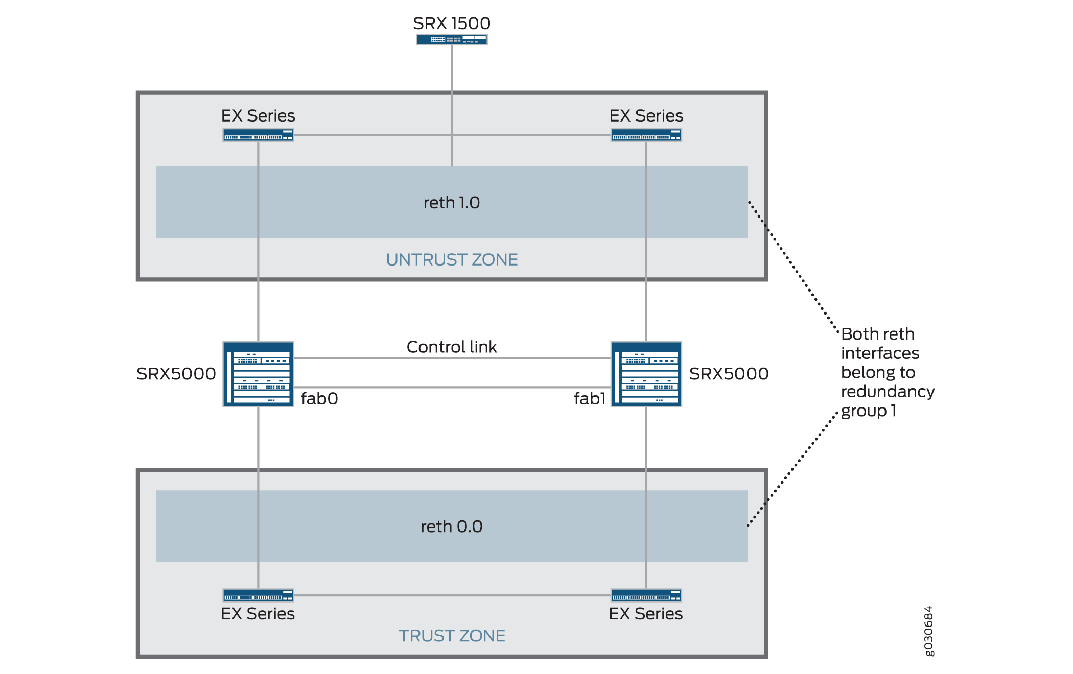
この場合、クラスタ内の 1 つのデバイスが IPsec トンネルで終端し、すべてのトラフィックを処理するために使用され、他のデバイスは障害発生時にのみ使用されます( 図 4 を参照)。障害が発生すると、バックアップ デバイスがプライマリになり、すべての転送を制御します。
アクティブ/パッシブ シャーシクラスター は、すべて同じ冗長グループに割り当てられた冗長イーサネットインターフェイス(reth)を使用することで実現できます。ノード内のアクティブなグループのインターフェイスのいずれかに障害が発生した場合、そのグループは非アクティブと宣言され、グループ内のすべてのインターフェイスが他のノードにフェイルオーバーします。
この構成は、冗長イーサネットインターフェイスがトンネルエンドポイントとして使用されるアクティブ/パッシブクラスターでサイトツーサイトIPsec トンネルを終端する方法を提供します。障害が発生すると、バックアップ用のSRXシリーズファイアウォールの冗長イーサネットインターフェイスがアクティブになり、トンネルがエンドポイントを変更して、新しいアクティブなSRXシリーズファイアウォールで終端するように強制されます。トンネルキーとセッション情報はシャーシ クラスタのメンバー間で同期されるため、フェイルオーバー時にトンネルを再ネゴシエートする必要はなく、確立されたすべてのセッションが維持されます。
RG0(ルーティングエンジン)に障害が発生した場合、ルーティングプロトコルは新しいプライマリノードで再確立する必要があります。VPNモニタリングまたはデッドピア検出が設定されていて、ルーティングが新しいRG0プライマリで再コンバージェンスする前にタイマーが切れた場合、VPNトンネルは停止し、再ネゴシエートされます。
動的トンネルは、異なるSPC間でロードバランシングを行うことはできません。
参照
例:IPsecトンネルを使用したアクティブ/パッシブシャーシクラスタペアの設定
この例では、SRXシリーズファイアウォールのIPsec トンネルを使用してアクティブ/パッシブシャーシクラスタリングを設定する方法を示しています。
必要条件
開始する前に、以下を実行します。
-
同一のハードウェア構成の2つのSRX5000モデル、1つのSRX1500またはSRX1600デバイス、4つのEXシリーズイーサネットスイッチを入手できます。
-
2 つのデバイスを物理的に接続し(ファブリックと制御ポートをバックツーバックで接続)、それらが同じモデルであることを確認します。SRX5000シリーズでは、ファブリックポートと制御ポートの両方を設定できます。
-
2台のデバイスをクラスタ モードに設定し、デバイスを再起動します。たとえば以下のように、両方のデバイスに動作モードコマンドを入力する必要があります。
-
ノード0:
user@host> set chassis cluster cluster-id 1 node 0 reboot -
ノード1:
user@host> set chassis cluster cluster-id 1 node 1 reboot
クラスタIDは両方のデバイスで同じですが、一方のデバイスがノード0でもう一方のデバイスがノード1であるため、ノードIDは異なっている必要があります。クラスタ ID の範囲は 1 から 255 です。クラスタ ID を 0 に設定することは、クラスタを無効にすることと同じです。
クラスタIDが15を超えると、ファブリックと制御リンクのインターフェイスがバックツーバックで接続されている場合のみ設定できます。
-
-
同一のハードウェア構成の2つのSRX5000モデル、1つのSRX1500エッジルーター、および4つのEXシリーズイーサネットスイッチを入手できます。
-
2 つのデバイスを物理的に接続し(ファブリックと制御ポートをバックツーバックで接続)、それらが同じモデルであることを確認します。SRX5000シリーズでは、ファブリックポートと制御ポートの両方を設定できます。
これ以降、ノード メンバー間のクラスタ設定は同期され、2台のデバイスは1台のデバイスとして機能します。メンバー固有の設定(各メンバーの管理ポートのIPアドレスなど)は、設定グループを使用して入力されます。
概要
この例では、クラスタ内の 1 つのデバイスが IPsec トンネルで終端し、すべてのトラフィックの処理に使用され、もう一方のデバイスは障害発生時にのみ使用されます。( 図 5 を参照)。障害が発生すると、バックアップ デバイスがプライマリになり、すべての転送を制御します。
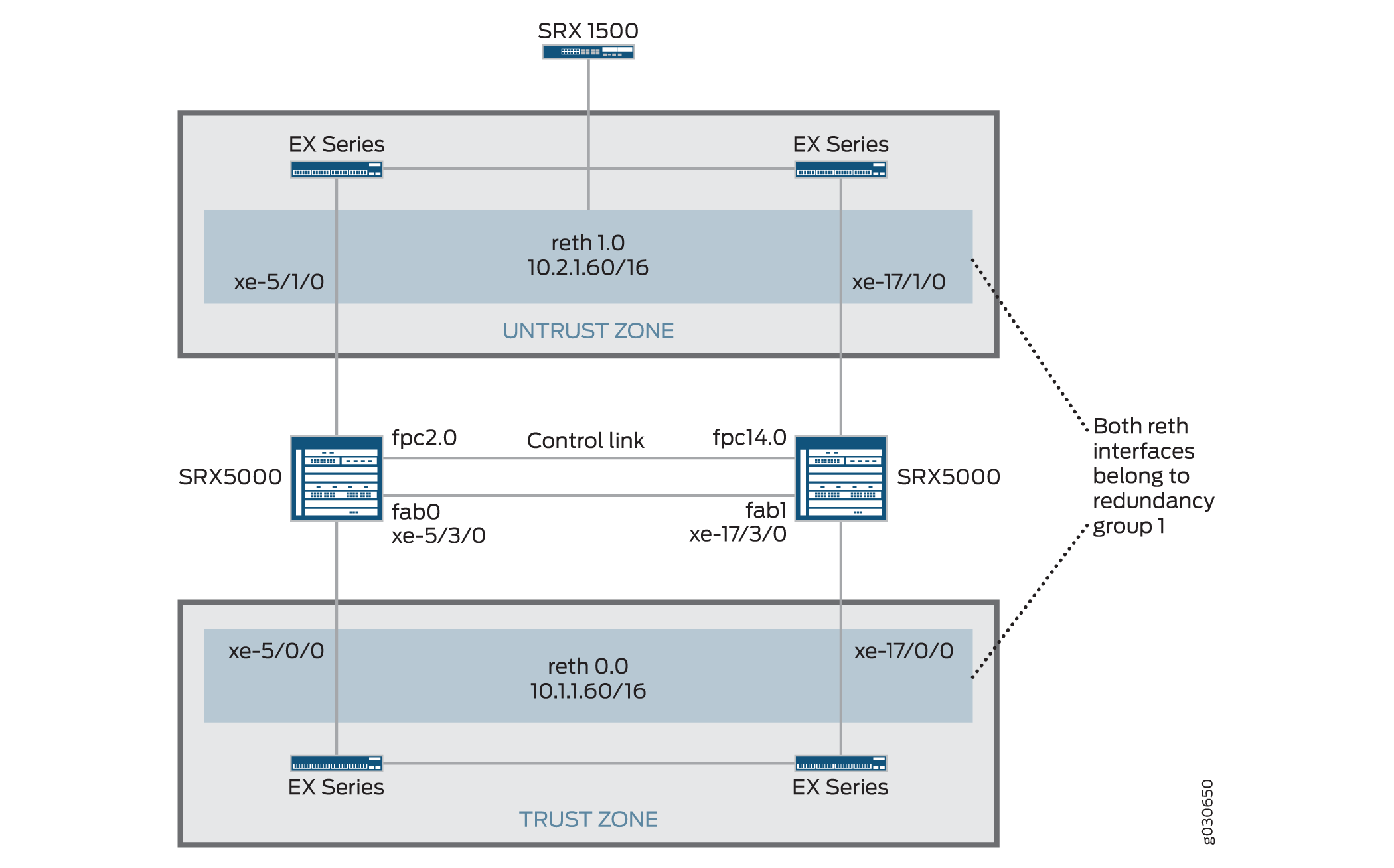
この例では、グループ( apply-groups コマンドで設定を適用)とシャーシ クラスタ情報を設定します。次に、IKE、IPsec、静的ルート、セキュリティ ゾーン、セキュリティ ポリシー パラメータを設定します。 表 5 から 表 11 を参照してください。
| 特徴 |
名前 |
設定パラメータ |
|---|---|---|
| グループ |
ノード0 |
|
| ノード1 |
|
| 特徴 |
名前 |
設定パラメータ |
|---|---|---|
| ファブリックリンク |
ファブ0 |
インターフェイス:xe-5/3/0 |
| ファブ1 |
インターフェイス:xe-17/3/0 |
|
| 冗長イーサネットインターフェイスの数 |
– |
2 |
| ハートビート間隔 |
– |
1000 |
| ハートビートしきい値 |
– |
3 |
| リダンダンシーグループ |
0 |
|
| 1 |
|
|
| インターフェイス監視
|
||
| インターフェイス |
xe-5/1/0 |
冗長な親: reth1 |
| xe-5/1/0 |
冗長な親: reth1 |
|
| xe-5/0/0 |
冗長な親: reth0 |
|
| xe-17/0/0 |
冗長な親: reth0 |
|
| reth0さん |
冗長グループ:1 |
|
|
||
| reth1 (レス1) |
冗長グループ:1 |
|
|
||
| st0 |
||
|
| 特徴 |
名前 |
設定パラメータ |
|---|---|---|
| 建議 |
プロポーザルセット標準 |
- |
| 政策 |
事前共有 |
|
| ゲートウェイ |
SRX1500-1 |
手記:
SRXシャーシクラスタリングでは、rethおよびlo0インターフェイスのみがIKE外部インターフェース設定でサポートされています。他のインターフェイス タイプも設定できますが、IPSec VPN が機能しない場合があります。lo0論理インターフェイスがIKEゲートウェイの外部インターフェースとして使用されている場合、RG0で設定することはできません。 |
| 特徴 |
名前 |
設定パラメータ |
|---|---|---|
| 建議 |
プロポーザルセット標準 |
– |
| 政策 |
標準 |
– |
| VPN |
SRX1500-1 |
手記:
手動 VPN 名とサイト間ゲートウェイ名を同じにすることはできません。 |
st0.16000からst0.16385までのセキュアトンネルインターフェイス(st0)は、マルチノード高可用性とシャーシクラスターでのHA制御リンク暗号化のために予約されています。これらのインターフェイスは、ユーザー設定可能なインターフェイスではありません。st0.0からst0.15999までのインターフェイスのみを使用できます。
| 名前 |
設定パラメータ |
|---|---|
| 0.0.0.0/0 |
ネクスト ホップ:10.2.1.1 |
| 10.3.0.0/16 |
ネクストホップ:10.10.1.2 |
| 名前 |
設定パラメータ |
|---|---|
| 信託 |
|
| 信頼できない |
|
| VPN |
|
| 目的 |
名前 |
設定パラメータ |
|---|---|---|
| このセキュリティ ポリシーは、trustゾーンからuntrustゾーンへのトラフィックを許可します。 |
任意 |
|
| このセキュリティ ポリシーは、trustゾーンからvpnゾーンへのトラフィックを許可します。 |
vpn-any(vpn-any) |
|
構成
プロシージャ
CLIクイック構成
この例を迅速に設定するには、以下のコマンドをコピーして、テキスト ファイルに貼り付け、改行を削除し、ネットワーク設定に一致させる必要がある詳細情報を変更し、コマンドを [edit] 階層レベルで CLI にコピー アンド ペーストして、設定モードから commit を入力します。
{primary:node0}[edit]
set chassis cluster control-ports fpc 2 port 0


                  set chassis cluster control-ports fpc 14 port 0


                  set groups node0 system host-name SRX5800-1


                  set groups node0 interfaces fxp0 unit 0 family inet address 172.19.100.50/24


                  set groups node1 system host-name SRX5800-2


                  set groups node1 interfaces fxp0 unit 0 family inet address 172.19.100.51/24


                  set apply-groups “${node}”


                  set interfaces fab0 fabric-options member-interfaces xe-5/3/0


                  set interfaces fab1 fabric-options member-interfaces xe-17/3/0


                  set chassis cluster reth-count 2


                  set chassis cluster heartbeat-interval 1000


                  set chassis cluster heartbeat-threshold 3


                  set chassis cluster node 0


                  set chassis cluster node 1


                  set chassis cluster redundancy-group 0 node 0 priority 254


                  set chassis cluster redundancy-group 0 node 1 priority 1


                  set chassis cluster redundancy-group 1 node 0 priority 254


                  set chassis cluster redundancy-group 1 node 1 priority 1


                  set chassis cluster redundancy-group 1 preempt


                  set chassis cluster redundancy-group 1 interface-monitor xe-5/0/0 weight 255


                  set chassis cluster redundancy-group 1 interface-monitor xe-5/1/0 weight 255


                  set chassis cluster redundancy-group 1 interface-monitor xe-17/0/0 weight 255


                  set chassis cluster redundancy-group 1 interface-monitor xe-17/1/0 weight 255


                  set interfaces xe-5/1/0 gigether-options redundant-parent reth1


                  set interfaces xe-17/1/0 gigether-options redundant-parent reth1


                  set interfaces xe-5/0/0 gigether-options redundant-parent reth0


                  set interfaces xe-17/0/0 gigether-options redundant-parent reth0


                  set interfaces reth0 redundant-ether-options redundancy-group 1


                  set interfaces reth0 unit 0 family inet address 10.1.1.60/16


                  set interfaces reth1 redundant-ether-options redundancy-group 1


                  set interfaces reth1 unit 0 family inet address 10.2.1.60/16


                  set interfaces st0 unit 0 multipoint family inet address 10.10.1.1/30


                  set security ike policy preShared mode main


                  set security ike policy preShared proposal-set standard


                  set security ike policy preShared pre-shared-key ascii-text "$ABC123"## Encrypted password


                  set security ike gateway SRX1500-1 ike-policy preShared


                  set security ike gateway SRX1500-1 address 10.1.1.90


                  set security ike gateway SRX1500-1 external-interface reth0.0


                  set security ipsec policy std proposal-set standard


                  set security ipsec vpn SRX1500-1 bind-interface st0.0


                  set security ipsec vpn SRX1500-1 vpn-monitor optimized


                  set security ipsec vpn SRX1500-1 ike gateway SRX1500-1


                  set security ipsec vpn SRX1500-1 ike ipsec-policy std


                  set security ipsec vpn SRX1500-1 establish-tunnels immediately


                  set routing-options static route 0.0.0.0/0 next-hop 10.2.1.1


                  set routing-options static route 10.3.0.0/16 next-hop 10.10.1.2


                  set security zones security-zone untrust host-inbound-traffic system-services all


                  set security zones security-zone untrust host-inbound-traffic protocols all


                  set security zones security-zone untrust interfaces reth1.0


                  set security zones security-zone trust host-inbound-traffic system-services all


                  set security zones security-zone trust host-inbound-traffic protocols all


                  set security zones security-zone trust interfaces reth0.0


                  set security zones security-zone vpn host-inbound-traffic system-services all 144


                  set security zones security-zone vpn host-inbound-traffic protocols all


                  set security zones security-zone vpn interfaces st0.0


                  set security policies from-zone trust to-zone untrust policy ANY match source-address any


                  set security policies from-zone trust to-zone untrust policy ANY match destination-address any


                  set security policies from-zone trust to-zone untrust policy ANY match application any


                  set security policies from-zone trust to-zone vpn policy vpn-any then permit
手順
IPsec トンネルでアクティブ/パッシブ シャーシ クラスタ ペアを設定するには、次の手順に従います。
-
制御ポートを設定します。
{primary:node0}[edit] user@host# set chassis cluster control-ports fpc 2 port 0 user@host# set chassis cluster control-ports fpc 14 port 0 -
管理インターフェイスを設定します。
{primary:node0}[edit] user@host# set groups node0 system host-name SRX5800-1 user@host# set groups node0 interfaces fxp0 unit 0 family inet address 172.19.100.50/24 user@host#set groups node1 system host-name SRX5800-2 user@host# set groups node1 interfaces fxp0 unit 0 family inet address 172.19.100.51/24 user@host# set apply-groups “${node}” -
ファブリックインターフェイスを設定します。
{primary:node0}[edit] user@host# set interfaces fab0 fabric-options member-interfaces xe-5/3/0 user@host# set interfaces fab1 fabric-options member-interfaces xe-17/3/0 -
冗長性グループを設定します。
{primary:node0}[edit] user@host# set chassis cluster reth-count 2 user@host# set chassis cluster heartbeat-interval 1000 user@host# set chassis cluster heartbeat-threshold 3 user@host# set chassis cluster node 0 user@host# set chassis cluster node 1 user@host# set chassis cluster redundancy-group 0 node 0 priority 254 user@host# set chassis cluster redundancy-group 0 node 1 priority 1 user@host# set chassis cluster redundancy-group 1 node 0 priority 254 user@host# set chassis cluster redundancy-group 1 node 1 priority 1 user@host# set chassis cluster redundancy-group 1 preempt user@host# set chassis cluster redundancy-group 1 interface-monitor xe-5/0/0 weight 255 user@host# set chassis cluster redundancy-group 1 interface-monitor xe-5/1/0 weight 255 user@host# set chassis cluster redundancy-group 1 interface-monitor xe-17/0/0 weight 255 user@host# set chassis cluster redundancy-group 1 interface-monitor xe-17/1/0 weight 255 -
冗長イーサネットインターフェイスを設定します。
{primary:node0}[edit] user@host# set interfaces xe-5/1/0 gigether-options redundant-parent reth1 user@host# set interfaces xe-17/1/0 gigether-options redundant-parent reth1 user@host# set interfaces xe-5/0/0 gigether-options redundant-parent reth0 user@host# set interfaces xe-17/0/0 gigether-options redundant-parent reth0 user@host# set interfaces reth0 redundant-ether-options redundancy-group 1 user@host# set interfaces reth0 unit 0 family inet address 10.1.1.60/16 user@host# set interfaces reth1 redundant-ether-options redundancy-group 1 user@host# set interfaces reth1 unit 0 family inet address 10.2.1.60/16 -
IPsecパラメータを設定します。
{primary:node0}[edit] user@host# set interfaces st0 unit 0 multipoint family inet address 10.10.1.1/30 user@host# set security ike policy preShared mode main user@host# set security ike policy preShared proposal-set standard user@host# set security ike policy preShared pre-shared-key ascii-text "$ABC123"## Encrypted password user@host# set security ike gateway SRX1500-1 ike-policy preShared user@host# set security ike gateway SRX1500-1 address 10.1.1.90 user@host# set security ike gateway SRX1500-1 external-interface reth0.0 user@host# set security ipsec policy std proposal-set standard user@host# set security ipsec vpn SRX1500-1 bind-interface st0.0 user@host# set security ipsec vpn SRX1500-1 vpn-monitor optimized user@host# set security ipsec vpn SRX1500-1 ike gateway SRX1500-1 user@host# set security ipsec vpn SRX1500-1 ike ipsec-policy std user@host# set security ipsec vpn SRX1500-1 establish-tunnels immediately -
スタティックルートを設定します。
{primary:node0}[edit] user@host# set routing-options static route 0.0.0.0/0 next-hop 10.2.1.1 user@host# set routing-options static route 10.3.0.0/16 next-hop 10.10.1.2 -
セキュリティ ゾーンを設定します。
{primary:node0}[edit] user@host# set security zones security-zone untrust host-inbound-traffic system-services all user@host# set security zones security-zone untrust host-inbound-traffic protocols all user@host# set security zones security-zone untrust interfaces reth1.0 user@host# set security zones security-zone trust host-inbound-traffic system-services all user@host# set security zones security-zone trust host-inbound-traffic protocols all user@host# set security zones security-zone trust interfaces reth0.0 user@host# set security zones security-zone vpn host-inbound-traffic system-services all user@host# set security zones security-zone vpn host-inbound-traffic protocols all user@host# set security zones security-zone vpn interfaces st0.0 -
セキュリティポリシーを設定します。
{primary:node0}[edit]
user@host# set security policies from-zone trust to-zone untrust policy ANY match source-address any
user@host# set security policies from-zone trust to-zone untrust policy ANY match destination-address any
user@host# set security policies from-zone trust to-zone untrust policy ANY match application any
user@host# set security policies from-zone trust to-zone vpn policy vpn-any then permit
業績
動作モードから、 show configuration コマンドを入力して設定を確認します。出力結果に意図した設定内容が表示されない場合は、この例の設定手順を繰り返して設定を修正します。
簡潔にするために、この show コマンド出力には、この例に関連する設定のみ含まれています。システム上のその他の設定はすべて省略記号(...)で置き換えられています。
user@host> show configuration
version x.xx.x;
groups {
node0 {
system {
host-name SRX58001;
}
interfaces {
fxp0 {
unit 0 {
family inet {
address 172.19.100.50/24;
}
}
}
}
}
node1 {
system {
host-name SRX58002;
}
interfaces {
fxp0 {
unit 0 {
family inet {
address 172.19.100.51/24;
}
}
}
}
}
}
apply-groups "${node}";
system {
root-authentication {
encrypted-password "$ABC123";
}
}
chassis {
cluster {
reth-count 2;
heartbeat-interval 1000;
heartbeat-threshold 3;
control-ports {
fpc 2 port 0;
fpc 14 port 0;
}
redundancy-group 0 {
node 0 priority 254;
node 1 priority 1;
}
redundancy-group 1 {
node 0 priority 254;
node 1 priority 1;
preempt;
interface-monitor {
xe–6/0/0 weight 255;
xe–6/1/0 weight 255;
xe–18/0/0 weight 255;
xe–18/1/0 weight 255;
}
}
}
}
interfaces {
xe–5/0/0 {
gigether–options {
redundant–parent reth0;
}
}
xe–5/1/0 {
gigether–options {
redundant–parent reth1;
}
}
xe–17/0/0 {
gigether–options {
redundant–parent reth0;
}
}
xe–17/1/0 {
gigether–options {
redundant–parent reth1;
}
}
fab0 {
fabric–options {
member–interfaces {
xe–5/3/0;
}
}
}
fab1 {
fabric–options {
member–interfaces {
xe–17/3/0;
}
}
}
reth0 {
redundant–ether–options {
redundancy–group 1;
}
unit 0 {
family inet {
address 10.1.1.60/16;
}
}
}
reth1 {
redundant–ether–options {
redundancy–group 1;
}
unit 0 {
family inet {
address 10.2.1.60/16;
}
}
}
st0 {
unit 0 {
multipoint;
family inet {
address 5.4.3.2/32;
}
}
}
}
routing–options {
static {
route 0.0.0.0/0 {
next–hop 10.2.1.1;
}
route 10.3.0.0/16 {
next–hop 10.10.1.2;
}
}
}
security {
zones {
security–zone trust {
host–inbound–traffic {
system–services {
all;
}
}
interfaces {
reth0.0;
}
}
security–zone untrust
host-inbound-traffic {
system-services {
all;
}
}
protocols {
all;
}
interfaces {
reth1.0;
}
}
security-zone vpn {
host-inbound-traffic {
system-services {
all;
}
}
protocols {
all;
}
interfaces {
st0.0;
}
}
}
policies {
from–zone trust to–zone untrust {
policy ANY {
match {
source–address any;
destination–address any;
application any;
}
then {
permit;
}
}
}
from–zone trust to–zone vpn {
policy vpn {
match {
source–address any;
destination–address any;
application any;
}
then {
permit;
}
}
}
}
}
デバイスの設定が完了したら、設定モードから commit を入力します。
検証
設定が正常に機能していることを確認します。
- シャーシ クラスタ ステータスの検証
- シャーシ クラスタ インターフェイスの検証
- シャーシ クラスタ統計情報の検証
- シャーシ クラスタ コントロール プレーン統計情報の検証
- シャーシ クラスタ データ プレーン統計情報の検証
- シャーシ クラスタ冗長グループ ステータスの検証
- ログを使用したトラブルシューティング
シャーシ クラスタ ステータスの検証
目的
シャーシ クラスタ ステータス、フェイルオーバー ステータス、冗長グループ情報を検証します。
アクション
動作モードから show chassis cluster status コマンドを入力します。
{primary:node0}
show chassis cluster status
Cluster ID: 1
Node                      Priority     Status    Preempt  Manual failover

Redundancy group: 0 , Failover count: 1
    node0                   1          primary   no       no
    node1                   254        secondary no       no

Redundancy group: 1 , Failover count: 1
    node0                   1          primary   yes      no
    node1                   254        secondary yes      no
シャーシ クラスタ インターフェイスの検証
目的
シャーシ クラスタ インターフェイスを確認します。
アクション
動作モードから show chassis cluster interfaces コマンドを入力します。
{primary:node0}
user@host> show chassis cluster interfaces
Control link name: fxp1

Redundant-ethernet Information:
    Name         Status      Redundancy-group
    reth0        Up          1
    reth1        Up          1

Interface Monitoring:
    Interface         Weight    Status    Redundancy-group
    xe-5/0/0          255       Up        1
    xe-5/1/0          255       Up        1
    xe-17/0/0         255       Up        1
    xe-17/1/0         255       Up        1
シャーシ クラスタ統計情報の検証
目的
シャーシ クラスタ サービスおよび制御リンク統計情報(送受信したハートビート)、ファブリック リンク統計情報(送受信したプローブ)、およびサービスで送受信された RTO 数に関する情報を検証します。
アクション
動作モードから show chassis cluster statistics コマンドを入力します。
{primary:node0}
user@host> show chassis cluster statistics

Control link statistics:
    Control link 0:
        Heartbeat packets sent: 258689
        Heartbeat packets received: 258684
        Heartbeat packets errors: 0
Fabric link statistics:
    Child link 0
        Probes sent: 258681
        Probes received: 258681
Services Synchronized:
    Service name                              RTOs sent    RTOs received
    Translation context                       0            0
    Incoming NAT                              0            0
    Resource manager                          6            0
    Session create                            161          0
    Session close                             148          0
    Session change                            0            0
    Gate create                               0            0
    Session ageout refresh requests           0            0
    Session ageout refresh replies            0            0
    IPSec VPN                                 0            0
    Firewall user authentication              0            0
    MGCP ALG                                  0            0
    H323 ALG                                  0            0
    SIP ALG                                   0            0
    SCCP ALG                                  0            0
    PPTP ALG                                  0            0
    RPC ALG                                   0            0
    RTSP ALG                                  0            0
    RAS ALG                                   0            0
    MAC address learning                      0            0
    GPRS GTP                                  0            0
シャーシ クラスタ コントロール プレーン統計情報の検証
目的
シャーシ クラスタ コントロール プレーン統計情報(送受信したハートビート)とファブリック リンク統計情報(送受信したプローブ)に関する情報を検証します。
アクション
動作モードから show chassis cluster control-panel statistics コマンドを入力します。
{primary:node0}
user@host> show chassis cluster control-plane statistics

Control link statistics:
    Control link 0:
        Heartbeat packets sent: 258689
        Heartbeat packets received: 258684
        Heartbeat packets errors: 0
Fabric link statistics:
    Child link 0
        Probes sent: 258681
        Probes received: 258681
シャーシ クラスタ データ プレーン統計情報の検証
目的
サービスで送受信されたRTO数に関する情報を確認します。
アクション
動作モードから show chassis cluster data-plane statistics コマンドを入力します。
{primary:node0}
user@host> show chassis cluster data-plane statistics

Services Synchronized:
    Service name                              RTOs sent    RTOs received
    Translation context                       0            0
    Incoming NAT                              0            0
    Resource manager                          6            0
    Session create                            161          0
    Session close                             148          0
    Session change                            0            0
    Gate create                               0            0
    Session ageout refresh requests           0            0
    Session ageout refresh replies            0            0
    IPSec VPN                                 0            0
    Firewall user authentication              0            0
    MGCP ALG                                  0            0
    H323 ALG                                  0            0
    SIP ALG                                   0            0
    SCCP ALG                                  0            0
    PPTP ALG                                  0            0
    RPC ALG                                   0            0
    RTSP ALG                                  0            0
    RAS ALG                                   0            0
    MAC address learning                      0            0
    GPRS GTP                                  0            0
シャーシ クラスタ冗長グループ ステータスの検証
目的
クラスタ内の両ノードの状態と優先度、プライマリ ノードの事前対応の有無または手動フェイルオーバーの有無に関する情報を検証します。
アクション
動作モードから chassis cluster status redundancy-group コマンドを入力します。
{primary:node0}
user@host> show chassis cluster status redundancy-group 1
Cluster ID: 1
    Node               Priority    Status    Preempt  Manual failover

	Redundancy-Group: 1, Failover count: 1
    node0              0           primary   yes      no
    node1              254         secondary yes      no
例:IPsecトンネルを使用したアクティブ/パッシブシャーシクラスターペアの設定(J-Web)
クラスターを有効にします。 例:IPsecトンネルを使用したアクティブ/パッシブシャーシクラスターペアの設定のステップ1を参照してください。
管理インターフェイスを設定します。 例:IPsecトンネルを使用したアクティブ/パッシブシャーシクラスターペアの設定のステップ2を参照してください。
ファブリックインターフェイスを設定します。 例:IPsecトンネルを使用したアクティブ/パッシブシャーシクラスターペアの設定のステップ3を参照してください。
冗長性グループを設定します。
[
Configure>System Properties>Chassis Cluster] を選択します。次の情報を入力し、[
Apply] をクリックします。冗長 ether-interfaces count:
2ハートビート間隔:
1000ハートビートしきい値:
3ノード:
0グループ番号:
0優先 順位:
254
次の情報を入力し、[
Apply] をクリックします。ノード:
0グループ番号:
1優先 順位:
254
次の情報を入力し、[
Apply] をクリックします。ノード:
1グループ番号:
0優先 順位:
1
次の情報を入力し、[
Apply] をクリックします。ノード:
1グループ番号:
1優先 順位:
1プリエンプト: チェックボックスを選択します。
インターフェイスモニター—インターフェイス:
xe-5/0/0インターフェイス モニター - 重量:
255インターフェイスモニター—インターフェイス:
xe-5/1/0インターフェイス モニター - 重量:
255インターフェイスモニター—インターフェイス:
xe-17/0/0インターフェイス モニター - 重量:
255インターフェイスモニター—インターフェイス:
xe-17/1/0インターフェイス モニター - 重量:
255
冗長イーサネットインターフェイスを設定します。
[
Configure>System Properties>Chassis Cluster] を選択します。[
xe-5/1/0] を選択します。「Redundant Parent」ボックスに「
reth1」と入力します。[
Apply] をクリックします。[
xe-17/1/0] を選択します。「Redundant Parent」ボックスに「
reth1」と入力します。[
Apply] をクリックします。[
xe-5/0/0] を選択します。「Redundant Parent」ボックスに「
reth0」と入力します。[
Apply] をクリックします。[
xe-17/0/0] を選択します。「Redundant Parent」ボックスに
reth0と入力します。[
Apply] をクリックします。例:IPsecトンネルを使用したアクティブ/パッシブシャーシクラスターペアの設定のステップ5を参照してください。
IPsec 設定を構成します。 例:IPsecトンネルを使用したアクティブ/パッシブシャーシクラスターペアの設定のステップ6を参照してください。
スタティックルートを設定します。
[
Configure>Routing>Static Routing] を選択します。[
Add] をクリックします。次の情報を入力し、[
Apply] をクリックします。静的ルート アドレス:
0.0.0.0/0ネクストホップアドレス:
10.2.1.1
次の情報を入力し、[
Apply] をクリックします。静的ルート アドレス:
10.3.0.0/16ネクストホップアドレス:
10.10.1.2
セキュリティ ゾーンを設定します。 例:IPsecトンネルを使用したアクティブ/パッシブシャーシクラスターペアの設定のステップ8を参照してください。
セキュリティポリシーを設定します。 例:IPsecトンネルを使用したアクティブ/パッシブシャーシクラスターペアの設定のステップ9を参照してください。
「
OK」をクリックして設定を確認し、設定の候補として保存し、「Commit Options>Commit」をクリックします。