EVPN Inter-VLAN Multicast Routing with Optimization
EVPN Inter-VLAN Multicast Routing without Optimization chapter explored the principles of Inter-VLAN multicast routing in an EVPN DC Fabric with PIM, using external M-Router and with PIM enabled on IRB on the BL devices. It also explored the characteristics of Inter-VLAN multicast in the absence of the optimizations like IGMP-Snooping, Selective (SMET) Forwarding, and Assisted Replication. In this chapter, we explore what happens if we turn ON these optimizations.
With optimizations, the basic L3-routing procedures for Inter-subnet Multicast do not change. Post routing the routed multicast traffic is selectively forwarded to only those PEs that expressed listener interest for that group. The optimized Intra-VLAN multicast routing procedures are followed for each of the receiver VLANs.
Inter-VLAN Multicast with Selective (SMET) Forwarding
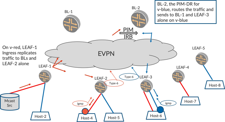
In Figure 1, LEAF-2 originates Type-6 on v-red and LEAF-3 originates Type-6 on v-blue based on received IGMP reports. BL-2, which is the PIM-DR for v-blue, routes the traffic from v-red onto v-blue. Post routing, BL-2 L2-forwards the traffic on v-blue to only LEAF-3 and BL-1 per Optimized Intra-subnet Multicast procedures described in EVPN Intra-VLAN Multicast with Optimization chapter. The LEAFs that do not have listeners for v-blue, LEAF-1, LEAF-2, and LEAF-5 are spared from receiving routed multicast traffic for v-blue.
Inter-VLAN Multicast with Multiple Listener VLANs
In an EVPN fabric, there will be several receiver VLANs where the traffic has to be routed. Selective Multicast Forwarding (SMET) can be appreciated in a scenario where there are several VLANs with Inter-VLAN multicast forwarding. Consider Figure 2 where there are two receiver VLANs, namely v-blue and v-green. The number of VLANs is in the order of hundreds. And let’s say BL-1 is the PIM-DR for blue and BL-2 is the PIM-DR for green.
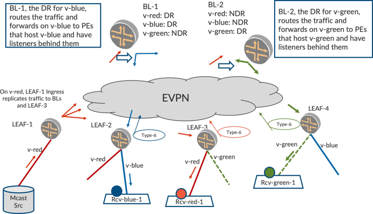
With optimized multicast enabled, LEAF-2 will originate Type-6 (v-blue) and LEAF-4 will originate Type-6 (v-green). Also, LEAF-3 will originate Type-6 (v-red). When the source starts sending traffic on v-red, LEAF-1 will L2-forward the traffic to the two BLs and to LEAF-3 on v-red. LEAF-3 will forward to its access Host Rcv-red-1.
When BL-1 receives the traffic on v-red it will route the traffic onto v-blue since it is PIM-DR on v-blue. Post routing on v-blue will L2-forward the traffic to the other BL and LEAF-2 per Intra-subnet selective multicast procedures. LEAF-2 will forward the traffic on v-blue to its access interface to Rcv-blue-1.
Similarly, when BL-2 receives the traffic on v-red it will route the traffic onto v-green since it is the PIM-DR on v-green. Post routing on v-green will L2-forward the traffic to the other BL and to LEAF-4 per selective multicast procedures. LEAF-4 will forward the traffic on its access interface to Rcv-green-1.
BL-1 will receive the same traffic from BL-2 on irb.v-green. This traffic will be dropped due to IIF-Mismatch since BL-1’s RPF to source is over irb.v-red.
Thus, traffic is sent only to the required PEs and only onto those access interfaces on the receiver VLANs, thus conserving bandwidth and resources on each receiver VLAN.
Inter-VLAN Multicast with AR and SMET
Now let’s use a typical EVPN data center fabric illustrated in Figure 3, where the BL devices are enabled with PIM on IRBs. Though BL L3-PIM devices are high-end, when several VLANs and multiple Ingress Replications have to be performed, to send to several LEAFs in the fabric there is a possibility of the BLs getting overwhelmed. Even if the BL devices held up well, in terms of replication, the link between the BLs and the Lean-Spine may not be able to carry the multiple replicated copies.
In addition to SMET, enabling AR in the fabric brings in additional gains in transferring the replication load from BL devices to the AR-Replicator and also reducing the bandwidth on the link between the BL and the AR-R.
In Figure 3, LEAF-2 and LEAF-4 have listener interest on v-blue while LEAF-2 and LEAF-5 have listener interest on v-green. Say BL-1 is the PIM DR for v-blue and BL-2 is PIM DR for v-green, and we have AR plus SMET optimization enabled in the data center fabric.
When the source sends traffic on v-red, LEAF-1, being the AR-LEAF, sends only a copy of the packet to the AR-Replicator, for example, AR-1. Now AR-1 replicates this packet to the BLs since BLs are running PIM, and resets the bit in Multicast Flags Community (MF-COM). Please see EVPN Intra-VLAN Multicast with Optimization chapter.
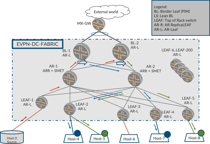
BL-1, being a PIM enabled device and the PIM DR on v-blue, routes the traffic from v-red to v-blue. Typically, without AR, BL would have replicated two copies to be sent to LEAF-2 and LEAF-4. Also, the link between BL-1 and AR-2 would be carrying two copies of the same packet. With AR, BL-1, being the AR-LEAF, sends only one packet to one of the AR-Replicators, say AR-2. Now AR-2 replicates the packet on v-blue to LEAF-2 and LEAF-4.
Similarly, BL-2, the PIM DR on v-green, routes the packet from v-red to v-green. Since BL-2 is an AR-LEAF, instead of making multiple copies it sends one copy to the replicator AR-2. AR-R2 duly replicates and sends the packet on v-green to LEAF-2 and LEAF-5.
LEAF-3 and the rest of the LEAFs (LEAF-6 to LEAF-200) are spared from receiving any traffic. Needless to say, the access interfaces on the LEAFs that don’t have listeners are also spared of traffic.
Thus, AR and SMET, when used in an Inter-VLAN multicast environment bring in the following benefits on each of the listener VLANs:
Core bandwidth conservation
Reduced Replication Load on LEAF and BLs
Selective Forwarding by the LEAFs, BLs, and the AR-Replicators
Reduced Link-utilization between LEAF/BL and the Lean Spines
Access side bandwidth conservation
Reduced load of processing unnecessary multicast traffic received from the core
In a scaled setup, such schemes of optimization help in reducing the load on packet replication, processing, and also the core-bandwidth utilization. Thus, AR plus SMET brings to EVPN data center fabric the equivalent of traditional selective P2MP multicast.
There’s also load sharing at various levels:
Leaf-layer: The LEAF devices pick one of the replicators for replication for different flows. By virtue of this, the multiple underlay links between the LEAF and the replicators are shared equitably.
BL-Layer: Different BL devices are PIM DRs for different VLANs. Thus the load of routing for different VLANs is shared amongst the BL devices.
When the LEAF devices are multihomed only the DF forwards, thus conserving the access bandwidth. The DF election is thus performed so that different LEAF devices among a multihomed set become DFs for different VLANs.
Optimized vis-à-vis Non-optimized Inter-VLAN Mcast
Let’s make some comparisons similar to how we calculated in Assisted Replication with SMET chapter. Consider a case where there are 200 LEAFs in a data center fabric. Say there is high volume of multicast traffic for 20 groups, each group has traffic rate of 1 Mbps, and there are 10 LEAFs in the fabric interested in each group in each VLAN. Further, assume there are 500 VLANs in the data center fabric. Let’s characterize the behavior with each mechanism.
Number of LEAFs in Fabric: N = 200
Number of groups: G = 20
Traffic Rate: R = 1 Mbps
Number of LEAFs interested in traffic per VLAN per group: T= 10
Number of VLANs in Fabric M = 500
Non-optimized Multicast
Core bandwidth consumption:
(N * G * R * M) = (200 * 20 * 1 * 500) = 2000 Gbps
Replication Load on BL:
(N * G * M) = 200 * 20 * 500 = = 2M times
Link bandwidth consumption between BL and Lean-Spine:
(N * G * R * M) = (200 * 20 * 1 * 500) = 2000 Gbps
Assisted Replication
Core bandwidth consumption:
(N * G * R * M) = (200 * 20 * 1 * 500) = 2000 Gbps
Replication Load on BL:
(1 * G * M) = 1 * 20 * 500 = 10K times
Link bandwidth consumption between BL and Lean-Spine:
(1 * G * R * M) = (1 * 20 * 1 * 500) = 10 Gbps
Optimized Multicast (SMET Forwarding) without AR
Core bandwidth consumption:
(T * G * R * M) = (10 * 20 * 1 * 500) = 100 Gbps
Replication Load on BL for each packet received from core:
(T * G * M) = (10 * 20 * 500) = 100K times
Link bandwidth consumption between LEAF and Lean-Spine:
(T * G * R * M) = (10 * 20 * 1 * 500) = 100,000 = 100 Gbps
AR + SMET
Core bandwidth consumption:
(T * G * R * M) = (10 * 20 * 1 * 500) = 100 Gbps
Replication Load on BL for each packet received from core:
(1 * G * M) = (1 * 20 * 500) = 10K times
Link bandwidth consumption between BL and Lean-Spine:
(1 * G * R * M) = (1 * 20 * 1 * 500) = 10 Gbps
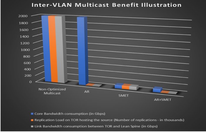
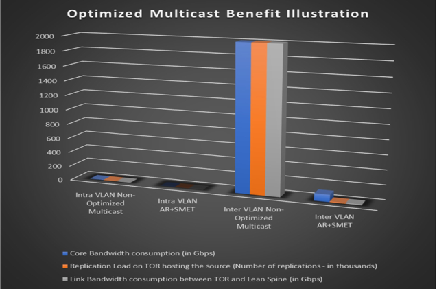
With AR and SMET you can see that the overall core bandwidth consumption is significantly reduced. Also, the utilization between BL and the Lean Spine device is considerably reduced. See Table 1 and Figure 4 and Figure 5. Also, the replication load on BLs is reduced.
Table 1: Bandwidth Consumption
Number of VLANs in the fabric: 500 | |||||
Number of TORs in the fabric: N = 200 | Number of Groups: G = 20 | ||||
Number of TORs interested in the fabric: T = 10 | Traffic Rate: R = 1 Mbps | ||||
Inter-VLAN Multicast | Non-Optimized Multicast | AR | SMET | AR + SMET | Gain Factor: AR+SMET vis-a-vis Non-optimized |
Core Bandwidth consumption (in Gbps) | 2000 | 2000 | 100 | 100 | 20 |
Replication Load on TOR hosting the source | 2000K | 10K | 100K | 10K | 200 |
Link Bandwidth consumption between TOR and Lean Spine (in Gbps) | 2000 | 10 | 100 | 10 | 200 |
Chapter Summary
This chapter has explored Inter-VLAN Multicast behavior when deployed with optimization. Inter-VLAN multicast, per se, has no procedural change. However, with the optimization schemes, the benefits accrue since these are applicable on each of the listener VLANs where traffic is routed. We also explored the different benefits quantitatively in a typical use case and illustrated how all of the optimization techniques from Part I of the book are playing a crucial role in Inter-VLAN multicast.
So having covered both Intra-VLAN and Inter-VLAN multicast within a data center fabric, it’s time to explore the different ways this fabric can be connected to the outside world and multicast traffic can be sent/ received from/to the fabric.
Configuration and Verification
So far our sources and receivers have all been on the same VLAN, VLAN-101. Having explored inter-VLAN multicast, we are now ready to look at the multicast behavior when we have the source(s) and receiver(s) within the DC but on different VLANs.
Before beginning, let’s stop all sources and receivers that were previously started.
Configuration
Though we have, so far, focused solely on VLAN-101, our base configuration has always included VLAN-102. So the configurations done in EVPN Inter-VLAN Multicast Routing without Optimization chapter are sufficient for this section and we can move on directly to traffic verification. Remember also that our configurations already include SMET and AR optimizations.
Traffic Verification
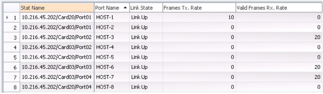
As before, start sending multicast traffic from Host-1 at 10 pps (packets per second) for group 225.1.1.1 in VLAN-101.
On Host-6 and Host-3, start receivers for the multicast group, 225.1.1.1, but this time on both VLAN-101 and VLAN-102.
From the RT statistics, you can see that the traffic sent by Host-1 at 10 pps is now received by the interested receivers, Host-6 and Host-3, and the legacy device, Host-7, in both VLAN-101 and VLAN-102, thereby resulting in 20 pps of incoming traffic on each of them.
Multicast Traffic Outputs - LEAF-1, LEAF-2, LEAF-4, LEAF-5, SPINE-2 (VLAN-101)
The traffic forwarding behavior for the multicast traffic arriving in VLAN-101 will be same as before on these devices. So this flow contributes to 10 pps of the traffic seen on Host-2, Host-6, and Host-8.
Note that the traffic is also replicated by SPINE-2 to BL-1 and BL-2. We have so far postponed looking at the traffic forwarding behavior on these devices. Now that inter VLAN procedures are understood, let’s see what happens to the traffic on these devices.
BL-1, BL-2
VLAN-101 does not have any access interfaces on the border-LEAF devices, hence there is no further switching of the multicast traffic on either one. However, a multicast (PIM+IGMP) enabled IRB is associated with the VLAN on both these devices.
Since BL-2 has a higher IP address, it is elected as the PIM-DR on irb.101 (VLAN-101).
On irb.102, since we have configured an explicit DR-priority on BL-1, in spite of having lower IP, it is elected as PIM DR on irb.102 (VLAN-102):
lab@BL-1> show pim interfaces instance VRF-1
Stat = Status, V = Version, NbrCnt = Neighbor Count,
S = Sparse, D = Dense, B = Bidirectional,
DR = Designated Router, DDR = Dual DR, DistDR = Distributed DR,
P2P = Point-to-point link, P2MP = Point-to-Multipoint,
Active = Bidirectional is active, NotCap = Not Bidirectional Capable
Name         Stat Mode IP V State      NbrCnt JoinCnt(sg/*g) DR address
irb.101       Up   S    4 2 NotDR,NotCap    1 1/0            18.18.18.2
irb.102       Up   S    4 2 DR,NotCap       1 0/0            19.19.19.1
lo0.1         Up   S    4 2 DR,NotCap       0 0/0       101.101.101.102
pime.32770 Up S 4 2 P2P,NotCap 0 0/0
lab@BL-2> show pim interfaces instance VRF-1
Stat = Status, V = Version, NbrCnt = Neighbor Count,
S = Sparse, D = Dense, B = Bidirectional,
DR = Designated Router, DDR = Dual DR, DistDR = Distributed DR,
P2P = Point-to-point link, P2MP = Point-to-Multipoint,
Active = Bidirectional is active, NotCap = Not Bidirectional Capable
Name         Stat Mode IP V State      NbrCnt JoinCnt(sg/*g) DR address
irb.101       Up    S   4 2 DR,NotCap       1 1/0            18.18.18.2
irb.102       Up    S   4 2 NotDR,NotCap    1 0/0            19.19.19.1
lo0.1         Up    S   4 2 DR,NotCap       0 0/0       102.102.102.103
pime.32769    Up    S   4 2 P2P,NotCap      0 0/0
Multicast Traffic Outputs – BL-1, BL-2
Since there is receiver interest on irb.102, BL-1 being the PIM DR on irb.102, routes the traffic arriving on irb.101 into irb.102 (i.e. VLAN-102):
lab@BL-1> show multicast route extensive instance VRF-1
Instance: VRF-1 Family: INET
Group: 225.1.1.1
		Source: 18.18.18.30/32
		Upstream interface: irb.101
		Downstream interface list:
			irb.102
		Number of outgoing interfaces: 1
		Session description: Unknown
		Statistics: 1 kBps, 10 pps, 917043 packets
		Next-hop ID: 131102
		Upstream protocol: PIM
		Route state: Active
		Forwarding state: Forwarding
		Cache lifetime/timeout: 360 seconds
		Wrong incoming interface notifications: 33
		Uptime: 00:03:15
BL-1 then forwards the traffic routed into VLAN-102 towards one of the AR-Replicator Spines: in this case SPINE-1 (AR-IP = 103.103.103.113).
In addition, the traffic is also sent on the VTEP towards the BL-2 (102.102.102.102) since it is multihomed to BL-1 (refer to Assisted Replication chapter: Enhanced-AR Forwarding Rules):
lab@BL-1> show interfaces vtep extensive | grep “Output packets.*pps|VXLAN Endpoint Address”
VXLAN Endpoint Type: Remote, VXLAN Endpoint Address: 102.102.102.102…
  Output packets:	4194	10 pps
VXLAN Endpoint Type: Remote, VXLAN Endpoint Address: 105.105.105.105…
  Output packets:	57	0 pps
VXLAN Endpoint Type: Remote, VXLAN Endpoint Address: 106.106.106.106…
  Output packets:	57	0 pps
VXLAN Endpoint Type: Remote, VXLAN Endpoint Address: 107.107.107.107…
  Output packets:	0	0 pps
VXLAN Endpoint Type: Remote, VXLAN Endpoint Address: 108.108.108.108…
  Output packets:	55	0 pps
VXLAN Endpoint Type: Remote, VXLAN Endpoint Address: 109.109.109.109…
  Output packets:	57	0 pps
VXLAN Endpoint Type: Remote, VXLAN Endpoint Address: 103.103.103.113…
  Output packets:	4212	9 pps
VXLAN Endpoint Type: Remote, VXLAN Endpoint Address: 103.103.103.103…
  Output packets:	1	0 pps
VXLAN Endpoint Type: Remote, VXLAN Endpoint Address: 104.104.104.104…
  Output packets:	0	0 pps
VXLAN Endpoint Type: Remote, VXLAN Endpoint Address: 104.104.104.114…
  Output packets:	3996	0 pps
Multicast Traffic Outputs - SPINE-1 (VLAN-102)
SPINE-1 selectively replicates the AR-tunnel traffic received from BL-1 in VLAN-102 to LEAF-1(105.105.105.105), LEAF-2(106.106.106.106), and LEAF-4(108.108.108.108) which have interested receivers, and legacy device LEAF-5(109.109.109.109):
lab@SPINE-1> show interfaces vtep extensive | grep “Output.*packets.*pps|VXLAN Endpoint Type”
VXLAN Endpoint Type: Remote, VXLAN Endpoint Address: 108.108.108.108…
  Output packets:	18136	9 pps
VXLAN Endpoint Type: AR Remote, VXLAN Endpoint Address: 108.108.108.108…
  Output packets:	0	0 pps
VXLAN Endpoint Type: Remote, VXLAN Endpoint Address: 101.101.101.101…
  Output packets:	5601	0 pps
VXLAN Endpoint Type: AR Remote, VXLAN Endpoint Address: 101.101.101.101…
  Output packets:	0	0 pps
VXLAN Endpoint Type: Remote, VXLAN Endpoint Address: 102.102.102.102…
  Output packets:	3525	0 pps
VXLAN Endpoint Type: AR Remote, VXLAN Endpoint Address: 102.102.102.102…
  Output packets:	0	0 pps
VXLAN Endpoint Type: Remote, VXLAN Endpoint Address: 109.109.109.109…
 Output packets:	18137	10 pps
VXLAN Endpoint Type: AR Remote, VXLAN Endpoint Address: 109.109.109.109…
   Output packets:	0	0 pps
VXLAN Endpoint Type: Remote, VXLAN Endpoint Address: 105.105.105.105…
  Output packets:	10984	10 pps
VXLAN Endpoint Type: AR Remote, VXLAN Endpoint Address: 105.105.105.105…
  Output packets:	0	0 pps
VXLAN Endpoint Type: Remote, VXLAN Endpoint Address: 106.106.106.106…
  Output packets:	10980	10 pps
VXLAN Endpoint Type: AR Remote, VXLAN Endpoint Address: 106.106.106.106…
  Output packets:	0	0 pps
VXLAN Endpoint Type: Remote, VXLAN Endpoint Address: 107.107.107.107…
  Output packets:	1614	0 pps
VXLAN Endpoint Type: AR Remote, VXLAN Endpoint Address: 107.107.107.107…
  Output packets:	0	0 pps
VXLAN Endpoint Type: Remote, VXLAN Endpoint Address: 104.104.104.104…
  Output packets:	10536	0 pps
VXLAN Endpoint Type: AR Remote, VXLAN Endpoint Address: 104.104.104.104…
  Output packets:	0	0 pps
VXLAN Endpoint Type: Remote, VXLAN Endpoint Address: 104.104.104.114…
  Output packets:	0	0 pps
Multicast Traffic Outputs - LEAF-1 (VLAN-102)
LEAF-1 receives 10 pps of multicast traffic from SPINE-1 in VLAN-102.
Though LEAF-1 has learned an interested IGMP receiver in VLAN-102 on its access interface ae1.0, CLASSICAL-DF-NDF rules prevent LEAF-1 from forwarding the multicast traffic on this interface.
The other access interfaces, ae0.0 and xe-0/0/4.0, do not have any receiver interest and IGMP-snooping procedures ensure that the traffic is not forwarded on these interfaces:
lab@LEAF-1> monitor interface traffic detail
Interface Link Input packets (pps) Output packets (pps) Description
…
xe-0/0/4   Up       0         (0)      2564        (0)    TO Host-2
…
ae0        Up     16487      (10)        0         (0)      TO CE-1
ae1        Up       0         (0)      9260       (10)      TO CE-2
…
So LEAF-1 effectively forwards only 10 pps in VLAN-101 to Host-3.
Multicast Traffic Outputs – LEAF-2 (VLAN-102)
LEAF-2 receives 10 pps of multicast traffic from SPINE-1 in VLAN-102.
Following CLASSICAL-DF-NDF rules and IGMP-snooping procedures on VLAN-102, LEAF-2 being the DF, forwards the multicast traffic to the interested IGMP receiver on its access interface ae1.0.
The other access interfaces, ae0.0 and xe-0/0/4.0, do not have any receiver interest and IGMP-snooping procedures ensure that the traffic is not forwarded on these interfaces:
lab@LEAF-2> monitor interface traffic detail
Interface Link Input packets (pps) Output packets (pps) Description
…
xe-0/0/4   Up       0         (0)        0         (0)    TO Host-4
…
ae0        Up       7         (0)        0         (0)      TO CE-1
ae1        Up      16         (0)      9561        (10)     TO CE-2
…
LEAF-2 forwards 10 pps in VLAN-102 to Host-3. Thus LEAF-1 and LEAF-2 together account for the total 20 pps traffic seen on Host-3.
Multicast Traffic Outputs – LEAF-4 (VLAN-102)
LEAF-4 receives 10 pps of multicast traffic from SPINE-1 in VLAN-102.
The access side IGMP-snooping functionality ensures that the multicast traffic arriving on LEAF-4 on VLAN-102 is forwarded on the single-homed interface xe-0/0/3.0 that has a receiver, but not on the multihomed interface ae0.0 that does not have a receiver.
Recall that traffic for VLAN-101 was also being forwarded on the interested single-homed interface xe-0/0/3.0. Thus, these together account for the 20 pps traffic seen egressing xe-0/0/3.0 and received on Host-6.
lab@LEAF-2> monitor interface traffic detail
Interface Link Input packets (pps) Output packets (pps) Description
…
xe-0/0/3   Up       0         (0)      8283        (20)   TO Host-6
ae0        Up       7         (0)        0          (0)     TO CE-3
…
Multicast Traffic Outputs - LEAF-5
LEAF-5 being a legacy device receives the traffic in VLAN-102 and floods it on its access interface, xe-0/0/2.0, even though it does not have a receiver.
Recall that traffic for VLAN-101 was also being forwarded on interface xe-0/0/2.0. Thus these together account for the 20 pps traffic seen egressing xe-0/0/2.0 and received on Host-7:
lab@LEAF-5> monitor interface traffic detail
Interface Link Input packets (pps) Output packets (pps) Description
…
xe-0/0/2   Up       0         (0)      8666        (20)   TO Host-7
…
Detailed Control Plane Verification
So far we have focused on the L2 multicast states built on the PEs. For traffic to be routed, in addition to the L2 multicast states, the L3 multicast states also need to be set correctly up on the PEs that are configured with IRBs and are acting as multicast routers in our case these are the Border-Leaf devices, BL-1 and BL-2. Once the multicast traffic is routed at the Border-Leaf PEs and forwarded towards the LEAF PEs, the L2 switching of traffic on the LEAF PEs occurs using the intra-VLAN states similar to what we have already looked at in detail in earlier chapters.
Verification of Layer 3 IGMP State
Verify that on BL-1, in addition to the IGMP snooping proxy state learned on VLAN-101 and VLAN-102, the IGMP group membership from EVPN has been learned on the corresponding L3 interfaces, irb.101 and irb.102, as well:
lab@BL-1> show evpn igmp-snooping proxy
Instance: default-switch
		VN Identifier: 101
			Group IP: 225.1.1.1, Source IP: 0.0.0.0
		VN Identifier: 102
			Group IP: 225.1.1.1, Source IP: 0.0.0.0

lab@BL-1> show igmp group detail
Interface: irb.101, Groups: 1
		Group: 225.1.1.1
			Group mode: Exclude
			Source: 0.0.0.0
			Source timeout: 0
			Last reported by: Local
			Group timeout:	0 Type: EVPN
…
Interface: irb.102, Groups: 1
		Group: 225.1.1.1
			Group mode: Exclude
			Source: 0.0.0.0
			Source timeout: 0
			Last reported by: Local
			Group timeout:	0 Type: EVPN
…
Verify that the same states have also been learned on BL-2:
lab@BL-2> show evpn igmp-snooping proxy
Instance: default-switch
		VN Identifier: 101
			Group IP: 225.1.1.1, Source IP: 0.0.0.0
		VN Identifier: 102
			Group IP: 225.1.1.1, Source IP: 0.0.0.0

lab@BL-2> show igmp group detail
Interface: irb.102, Groups: 1
		Group: 225.1.1.1
			Group mode: Exclude
			Source: 0.0.0.0
			Source timeout: 0
			Last reported by: Local
			Group timeout:	0 Type: EVPN
…

Interface: irb.101, Groups: 1
		Group: 225.1.1.1
			Group mode: Exclude
			Source: 0.0.0.0
			Source timeout: 0
			Last reported by: Local
			Group timeout:	0 Type: EVPN
…
Verification of Layer 3 PIM State
Verify that on BL-1 and BL-2 PIM state has been created for the group:
lab@BL-1> show pim join extensive instance VRF-1
Instance: PIM.VRF-1 Family: INET
R = Rendezvous Point Tree, S = Sparse, W = Wildcard
Group: 225.1.1.1
		Source: *
		RP: 101.101.101.102
		Flags: sparse,rptree,wildcard
		Upstream interface: Local
		Upstream neighbor: Local
		Upstream state: Local RP
		Uptime: 00:05:44
		Downstream neighbors:
			Interface: irb.101
				18.18.18.1 State: Join Flags: SRW Timeout: Infinity
				Uptime: 00:05:44 Time since last Join: 00:05:44
			Interface: irb.102
 			19.19.19.1	State: Join Flags: SRW Timeout: Infinity
				Uptime: 00:05:44 Time since last Join: 00:05:44
		Number of downstream interfaces: 2
		Number of downstream neighbors: 2
Group: 225.1.1.1
		Source: 18.18.18.30
		Flags: sparse,spt
		Upstream interface: irb.101
		Upstream neighbor: Direct
		Upstream state: Local Source, Local RP, No Prune to RP
		Keepalive timeout: 335
		Uptime: 00:20:58
		Downstream neighbors:
			Interface: irb.102
				19.19.19.2	State: Join Flags: S Timeout: Infinity
				Uptime: 00:05:53 Time since last Join: 00:05:53
		Number of downstream interfaces: 1
		Number of downstream neighbors: 1


lab@BL-2> show pim join extensive instance VRF-1
Instance: PIM.VRF-1 Family: INET
R = Rendezvous Point Tree, S = Sparse, W = Wildcard
Group: 225.1.1.1
		Source: *
		RP: 102.102.102.103
		Flags: sparse,rptree,wildcard
		Upstream interface: Local
		Upstream neighbor: Local
		Upstream state: Local RP
		Uptime: 00:05:53
		Downstream neighbors:
			Interface: irb.102
				19.19.19.2 State: Join Flags: SRW Timeout: Infinity
				Uptime: 00:05:53 Time since last Join: 00:05:53
			Interface: irb.101
				18.18.18.2 State: Join Flags: SRW Timeout: Infinity
				Uptime: 00:05:53 Time since last Join: 00:05:53
		Number of downstream interfaces: 2
		Number of downstream neighbors: 2
Group: 225.1.1.1
		Source: 18.18.18.30
		Flags: sparse,spt
		Upstream interface: irb.101
		Upstream neighbor: Direct
		Upstream state: Local Source, Local RP, No Prune to RP
		Keepalive timeout: 328
		Uptime: 00:21:07
		Downstream neighbors:
			Interface: irb.101
				18.18.18.2 State: Join Flags: S Timeout: Infinity
				Uptime: 00:05:53 Time since last Join: 00:05:53
		Number of downstream interfaces: 1
		Number of downstream neighbors: 1
Verification of Layer 3 Multicast Forwarding State
Verify that BL-1 receives the traffic in the source VLAN-101 on irb.101, and being the PIM DR on the receiver VLAN, VLAN-102 (irb.102) routes the traffic into VLAN-102 via irb.102:
lab@BL-1> show multicast route extensive instance VRF-1
Instance: VRF-1 Family: INET
Group: 225.1.1.1
		Source: 18.18.18.30/32
		Upstream interface: irb.101
		Downstream interface list:
			irb.102
		Number of outgoing interfaces: 1
		Session description: Unknown
		Statistics: 1 kBps, 10 pps, 917043 packets
		Next-hop ID: 131102
		Upstream protocol: PIM
		Route state: Active
		Forwarding state: Forwarding
		Cache lifetime/timeout: 360 seconds
		Wrong incoming interface notifications: 33
		Uptime: 00:03:15
Verify that BL-2 receives the traffic in the source VLAN-101 on irb.101, but since it is not the PIM DR on the receiver VLAN, VLAN-102 (irb.102), it does not route the traffic into VLAN-102 via irb.102:
lab@BL-2> show multicast route extensive instance VRF-1
Instance: VRF-1 Family: INET
Group: 225.1.1.1
		Source: 18.18.18.30/32
		Upstream interface: irb.101
		Number of outgoing interfaces: 0
		Session description: Unknown
		Statistics: 1 kBps, 10 pps, 10575 packets
		Next-hop ID: 0
		Upstream protocol: PIM
		Route state: Active
		Forwarding state: Forwarding
		Cache lifetime/timeout: 360 seconds
		Wrong incoming interface notifications: 0
		Uptime: 00:21:07
Verification of Layer 2 Multicast Forwarding State in the Routed VLAN
On BL-1, the traffic thus routed into VLAN-102 via irb.102 will then be forwarded in VLAN-102 based on the L2 multicast forwarding state created for group 225.1.1.1, and source 18.18.18.30 in VLAN-102:
Since we are using AR, verify that the traffic is forwarded via the load balancing next hop to one of the AR-Rs:
lab@BL-1> show multicast snooping route extensive VLAN VLAN-102 group 225.1.1.1 sourceprefix
18.18.18.30
Group: 225.1.1.1/32
    Source: 18.18.18.30/32
    Vlan: VLAN-102
    Mesh-group: __all_ces__
          Downstream interface list:
        evpn-core-nh -(131092)
…
lab@BL-1> show evpn multicast-snooping next-hops 131092 detail
…
ID     Refcount KRefcount Downstream interface Addr
131092    3         1     131084
                          Flags 0x2100 type 0x18 members 0/0/1/0/0
                          Address 0xe531928
lab@BL-1> show evpn multicast-snooping assisted-replication next-hops index 131084
Instance: default-switch
AR Role: AR Leaf
  VN Identifier: 102
   Load Balance Nexthop Index: 131084
     Load balance to:
     Nexthop Index Interface   AR IP
     1777          vtep.32777 103.103.103.113
     1794          vtep.32780 104.104.104.114
The AR-R receiving this traffic in VLAN-102, will selectively forward it in VLAN-102 to the interested PEs. This is plain intra-VLAN forwarding that we have discussed in previous chapters; the verification is left as an exercise for the reader.