Assisted Replication with SMET
Multicast So Far
Let’s quickly revisit the different features described earlier in this book to provide context for this chapter on AR+SMET:
Non-optimized multicast: This is the simplest case, where multicast traffic is flooded everywhere (both to access and to all PEs in the core).
Assisted Replication: This is the case where the replication load is transferred from the LEAF devices to the replicator devices. In this case, too, the traffic is flooded to all the access interfaces and to all the EVPN PEs in the core; only the replication load is transferred from the LEAF to the replicator, while the replicator floods the traffic to all PEs.
IGMP-Snooping and Selective (SMET) Forwarding: In this case we enabled IGMP-snooping on a VLAN, by virtue of which traffic is forwarded only on those access interfaces where there is listener interest for the group. Also, traffic is forwarded only to those EVPN PEs in the core that have listener interest behind them (signaled by Type-6) – in this scheme, the replication load towards EVPN core, though significantly reduced due to selective forwarding, is still on the LEAF.
AR + SMET
In a data center fabric with several LEAF devices and a high volume of multicast traffic, it may be effective to have a combination of the features of IGMP-Snooping, Selective (SMET) Forwarding, and AR to conserve core access bandwidth and also transfer replication load from LEAF devices. That is to say, it is a good practice to configure both AR and IGMP-snooping in the fabric to get the best of both worlds. This is commonly referred to as AR+SMET.
With this scheme, both AR and IGMP-snooping will be enabled on LEAF, LS, and BL devices. The LEAF devices and BL devices will have the role of AR-LEAF, while the LS-1 device will be configured with the role of AR-Replicator.
For the AR-Replicators to help optimized forwarding in the core, they will be enabled with EVPN. Therefore these devices originate and process EVPN NLRI routes.
AR+SMET Roles and Configuration
The LEAF and BL devices in this scheme are configured as follows:
IGMP-snooping on access interface: Traffic is forwarded only on those access interfaces where there is listener interest for the group. (IGMP Report)
Selective (SMET) Forwarding: Traffic is forwarded only towards those EVPN PEs that express listener interest for the group with Type-6 and to PIM devices.
AR-LEAF Role: The LEAF based on AR-LEAF Role, sends the traffic only to the Replicator. AR-LEAF is configured on the LEAFs.
The LS devices in this scheme are configured as follows:
EVPN Family: In prior chapters, the Lean Spine devices were participating in the underlay. In Assisted Replication chapter, the Lean-Spine device participated in EVPN in order to originate Type-3 AR and IR NLRI Routes and build a provider tunnel. In this case, too, an EVPN family would need to be enabled. Additionally, with IGMP-snooping, the Type-6 routes received from the LEAFs will be processed to build a next hop (OIL), which has only the interested listeners.
AR-Replicator: To help transfer the load from the LEAF devices to the AR-R. The Replicator configuration is enabled on the LS devices.
Selective (SMET) Forwarding: The Replicator devices forward the traffic only to those EVPN PEs that have expressed listener interest. This is achieved by configuring IGMP-snooping on the VLANs.
Enhanced AR Mode: The AR devices, when they are not able to retain the source-IP of the incoming packet, have to ensure that the packet is not sent to the multihomed peers of the PE that originated the traffic. Please refer to the section, Assisted Replication in Multihoming Environment, in Assisted Replication chapter.
This is relevant with SMET as well. For example, when we have AR plus SMET, the LEAF devices should forward the packet to its multihomed peers and the AR-R should skip forwarding to the multihomed peers of the PE that originated the traffic. Additionally, by virtue of SMET forwarding, the LEAF should send the traffic to the multihomed PEs only if there is listener interest for the group.
Summary Configuration of Features:
BL and LEAF devices: IGMP-Snooping + AR-LEAF Role
LS devices: IGMP-Snooping + AR-Replicator Role
AR+SMET Procedure
Consider Figure 1, where a listener comes up behind LEAF-4 and LEAF-5 for group G1. LEAF-4 and LEAF-5 send a Type-6 route for the group G1. This Type-6 is received by all EVPN PEs. LEAF-1 and AR-Replicators build SMET forwarding state for this group G1 with the relevant LEAFs alone in the OIL.
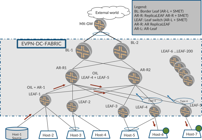
The overall objective is that the traffic from behind LEAF-1 has to be forwarded only to LEAF-4 and LEAF-5. Also, the objective is that LEAF-1 sends only one copy of the traffic to AR-R1 and AR-R1 replicates to LEAF-4 and LEAF-5.
LEAF-1, based on SMET forwarding principles, adds the OIL for group G since there is remote listener interest for group G1. Since LEAF-1 is AR-LEAF, it adds only AR-R1 in its OIL. AR-R1 based on SMET forwarding principles adds the OIL for group G with LEAF-4 and LEAF-5.
LEAF-1 sends one copy to AR-1 and this is replicated by AR-1 to LEAF-4 and LEAF-5 alone. Traffic is not sent to the LEAF devices (LEAF-2, LEAF-4, LEAF-6, LEAF-200) thereby conserving core bandwidth, replication, and processing loads.
AR Plus SMET Enhanced Mode Procedures
The procedures for AR plus SMET in Enhanced Mode are similar to what was described earlier in this chapter, since the AR-R is not capable of retaining the Src-IP of the incoming packet from LEAF-1, AR-R skips replicating to all the LEAFs that are multihomed to LEAF-1. To be able to keep the local-bias behavior intact, LEAF-1 ingress replicates the packet to LEAF-2.
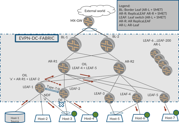
There is listener interest from Host-3, Host-4, Host-6, and Host-7. We can see that Host-3 and Host-4 are behind LEAF-2 which is multihomed to LEAF-1. Also, the report from Host-3 would be synchronized using the Type-7/8 principles described in EVPN Intra-Multicast Optimization with Multihoming chapter.
Now LEAF-1 has received Type-6 from LEAF-2, LEAF-4, and LEAF-5. Since LEAF-1 is configured as an AR-Leaf and also has deduced that it is multihomed to LEAF-2, it sends one copy to AR-R1 over AR-Tunnel and one copy to LEAF-2 over IR-Tunnel. Also, since traffic is coming from access interface, LEAF-1 forwards the traffic to Host-3 due to (SRC-LOCAL-BIAS).
On receiving the packet from LEAF-1, LEAF-2 does not forward to Host-3 despite being DF (DST-LOCAL-BIAS) since the packet arrived from multihomed-peer (S-VTEP-IP). However, LEAF-2 forwards the traffic to Host-4 since it is a single-homed interface (SH-FWD).
AR+SMET Benefit Illustration
Let’s consider a case where there are 200 LEAFs in a DC-Fabric. There is a high volume of multicast traffic for 20 groups G1, and each group has a traffic rate of 1 Mbps. There are 10 LEAFs in the fabric interested in each group. Let’s characterize the behavior with each mechanism.
Number of LEAFs in Fabric: N = 200
Number of groups: G = 20
Traffic Rate: R = 1 Mbps
Number of LEAFs interested in traffic: T= 10
Non-optimized Multicast
Core bandwidth consumption:
(N * G * R) = (200 * 20 * 1) = 4000 Mbps
Replication Load on LEAF hosting the source:
(N * G) = 200 * 20 = 4000 times
Link bandwidth consumption between LEAF and Lean-Spine:
(N * G * R) = (200 * 20 * 1) = 4000 Mbps
Assisted Replication (AR):
Core bandwidth consumption:
(N * G * R) = (200 * 20 * 1) = 4000 Mbps
Replication Load on LEAF hosting the source:
(1 * G) = 1 * 20 = 20 times
Link bandwidth consumption between LEAF and Lean-Spine:
(1 * G * R) = (1 * 20 * 1) = 20 Mbps
Optimized Multicast (SMET Forwarding) without AR
Core bandwidth consumption:
(T * G * R) = (10 * 20 * 1) = 200 Mbps
Replication Load on LEAF hosting the source:
(T * G) = 10 * 20 = 200 times
Link bandwidth consumption between LEAF and Lean-Spine:
(T * G * R) = (10 * 20 * 1) = 200 Mbps
AR + SMET
Core bandwidth consumption:
(T * G * R) = (10 * 20 * 1) = 200 Mbps
Replication Load on LEAF for each packet received from access:
(1 * G) = 1 * 20 = 20 times
Link bandwidth consumption between LEAF and Lean-Spine:
(1 * G * R) = (1 * 20 * 1) = 20 Mbps
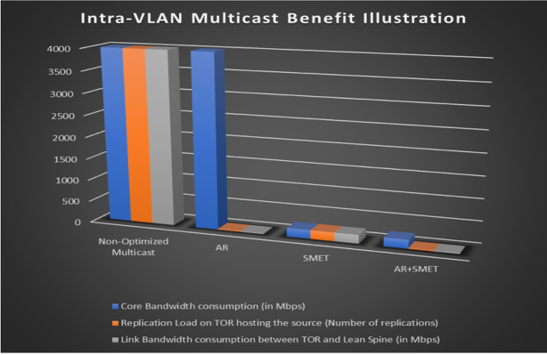
You can see that with AR+SMET, the overall core bandwidth consumption is significantly reduced. Also, the link utilization between LEAF and the Lean Spine device is considerably reduced, and the replication load on LEAF is reduced.
Number of TORs in the fabric: N = 200 | Number of Groups: G = 20 |
Number of TORs interested in the fabric: T = 10 | Traffic Rate: R = 1 Mbps |
Intra-VLAN Multicast | Non-Optimized Multicast | AR | SMET | AR + SMET | Gain Factor: AR+SMET vis-a-vis Non-optimized |
Core Bandwidth consumption (in Mbps) | 4000 | 4000 | 200 | 200 | 20 |
Replication Load on TOR hosting the source | 4000 | 20 | 200 | 20 | 200 |
Link Bandwidth consumption between TOR and Lean Spine (in Mbps) | 4000 | 20 | 200 | 20 | 200 |
By way of this scenario, we have achieved the objectives of optimized multicast and also replication load transfer from LEAF to AR-R, as graphed in Figure 3
The optimizations described thus far are applicable for a single-VLAN. When we visit Inter-VLAN routing/and forwarding, all of these optimizations will play a key role in significantly reducing the overall traffic.
Chapter Summary
This chapter explored AR+SMET and the procedures for the same. It addressed how an AR in conjunction with SMET and IGMP-snooping significantly reduces the core-bandwidth utilization, link bandwidth utilization between LEAF and Lean-Spine, the Replication Load on the LEAF, and the processing load of LEAFs from unnecessary traffic. We considered a typical use case and calculated the traffic utilization and replication load on different devices in order to appreciate the benefits of these optimization techniques when deployed in unison.
Configuration
Figure 4 illustrates our reference topology.
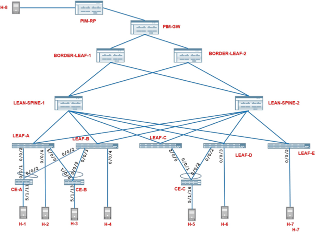
Now let’s see how the use of AR further optimizes our IGMP-snooping enabled network.
Configuration Details
Let’s turn on AR on the EVPN PEs.
We will configure all our existing IGMP-snooping enabled EVPN PEs (LEAF-1 through LEAF-4, BL-1, and BL-2) as AR LEAF (AR-LEAF) devices and configure the erstwhile “Lean” spine PEs as EVPN PEs and use them as AR Replicator (AR-Replicator) devices for the network.
Configuring the EVPN overlay on SPINE-1
Copy and paste this configuration on SPINE-1.
Configure I-BGP for routing in the overlay:
Configure the customer VLANs:
Configure EVPN to extend the customer VLANs:
Configure IGMP-snooping on the customer VLANs:
Configuring the EVPN Overlay on SPINE-2
Copy and paste the below configuration on SPINE-2.
Configure I-BGP for routing in the overlay:
Configure the customer VLANs:
Configure EVPN to extend the customer VLANs:
Configure IGMP-snooping on the customer VLANs:
Configuring Spine PEs as Overlay BGP Neighbors on the LEAF and Border-LEAF PEs
Copy and paste the below configuration on the following devices:
LEAF-1, LEAF-2, LEAF-3, LEAF-4, BL-1, BL-2
Configuring LEAF and Border-LEAFPEs as AR-LEAF
Copy and paste the below configuration on the following devices:
LEAF-1, LEAF-2, LEAF-3, LEAF-4, BL-1, BL-2
Configuring SPINE-1 as AR-Replicator
Copy and paste the below configuration on SPINE-1.
Configure a secondary loopback address on SPINE-1:
Configure AR-Replicator using the secondary loopback IP as the AR-Replicator IP:
Configuring SPINE-2 as AR-Replicator
Copy and paste the below configuration on SPINE-2.
Configure a secondary loopback address on SPINE-2:
Configure AR-Replicator using the secondary loopback IP as the AR-Replicator IP:
Traffic Verification
In EVPN Intra-Multicast Optimization with Multihoming chapter we started traffic from Host-1 and started receivers on Host-6 and Host-3. Having now turned on AR, let’s see how the traffic forwarding has changed in the network.
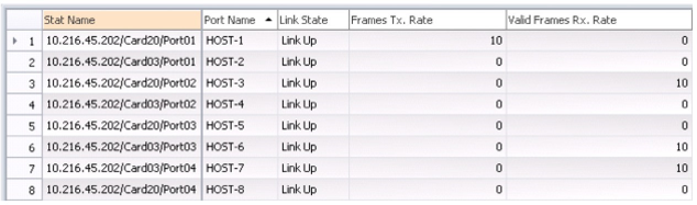
From the RT statistics in Figure 5, you can see that the traffic sent by Host-1 at 10 pps continues to be received by the interested single-homed receiver, Host-6, the interested multihomed receiver Host-3, and the legacy device, Host-7 in VLAN-101.
So what has changed? Let’s look at LEAF-1 again.
Multicast Traffic Outputs - LEAF-1
Just as before, the load-balanced multicast traffic arrives on access interface, ae0 on LEAF-1 and is forwarded on its access interface ae1.0 on which it has learned an IGMP report.
But things have changed in the core. Unlike before, now LEAF-1 sends out only two copies of the packet towards the core, thereby reducing the replication load on LEAF-1 and also conserving the physical link bandwidth between LEAF-1 and the Spine.
The multicast traffic is sent towards one of the AR-Replicator Spines, in our case SPINE-2. Note that this traffic is sent to the AR-IP of SPINE-2 (104.104.104.114).
In addition, the traffic is also sent on the VTEP towards the multi-homing peer PE, LEAF-2 (106.106.106.106):
lab@LEAF-1> show interfaces vtep extensive | grep “VXLAN Endpoint Type:.*Remote|Output packets.*pps”
VXLAN Endpoint Type: Remote, VXLAN Endpoint Address: 106.106.106.106…
  Output packets:	844	9 pps
VXLAN Endpoint Type: Remote, VXLAN Endpoint Address: 107.107.107.107…
  Output packets:	0	0 pps
VXLAN Endpoint Type: Remote, VXLAN Endpoint Address: 108.108.108.108…
  Output packets:	2847	0 pps
VXLAN Endpoint Type: Remote, VXLAN Endpoint Address: 101.101.101.101…
  Output packets:	3536	0 pps
VXLAN Endpoint Type: Remote, VXLAN Endpoint Address: 102.102.102.102…
  Output packets:	3536	0 pps
VXLAN Endpoint Type: Remote, VXLAN Endpoint Address: 109.109.109.109…
  Output packets:	3536	0 pps
VXLAN Endpoint Type: Remote, VXLAN Endpoint Address: 103.103.103.113…
  Output packets:	222	0 pps
VXLAN Endpoint Type: Remote, VXLAN Endpoint Address: 103.103.103.103…
  Output packets:	0	0 pps
VXLAN Endpoint Type: Remote, VXLAN Endpoint Address: 104.104.104.104…
  Output packets:	0	0 pps
VXLAN Endpoint Type: Remote, VXLAN Endpoint Address: 104.104.104.114…
  Output packets:	1521	10 pps
Multicast Traffic Outputs - SPINE-2
The multicast traffic load balanced between the AR-Replicators by LEAF-1 is received by SPINE-2 on its AR-tunnel, vtep.32782:
lab@SPINE-2> show interfaces vtep extensive | grep “VXLAN Endpoint Type:AR Remote|Input packets.*pps”
…
VXLAN Endpoint Type: AR Remote, VXLAN Endpoint Address: 105.105.105.105, L2 Routing Instance: default-switch, L3 Routing Instance: default
Input packets:	1414	9 pps
…
SPINE-2 selectively replicates this traffic only to the interested AR-LEAF PEs. The traffic is forwarded on the VTEPs towards Border-LEAF PEs (101.101.101.101 and 102.102.102.102) and on the VTEP towards LEAF-5 (109.109.109.109).
The traffic is also sent on the VTEP towards LEAF-4 (108.108.108.108) that has interested receivers AND is not multihomed to the source PE, LEAF-1:
lab@SPINE-2> show interfaces vtep extensive | grep “VXLAN Endpoint Type:.*Remote|Output packets.*pps”
VXLAN Endpoint Type: Remote, VXLAN Endpoint Address: 108.108.108.108…
  Output packets:	1418	10 pps
VXLAN Endpoint Type: AR Remote, VXLAN Endpoint Address: 108.108.108.108…
  Output packets:	0	0 pps
VXLAN Endpoint Type: Remote, VXLAN Endpoint Address: 101.101.101.101…
  Output packets:	1412	9 pps
VXLAN Endpoint Type: AR Remote, VXLAN Endpoint Address: 101.101.101.101…
  Output packets:	0	0 pps
VXLAN Endpoint Type: Remote, VXLAN Endpoint Address: 102.102.102.102…
  Output packets:	1419	10 pps
VXLAN Endpoint Type: AR Remote, VXLAN Endpoint Address: 102.102.102.102…
  Output packets:	0	0 pps
VXLAN Endpoint Type: Remote, VXLAN Endpoint Address: 109.109.109.109…
  Output packets:	1419	9 pps
VXLAN Endpoint Type: AR Remote, VXLAN Endpoint Address: 109.109.109.109…
  Output packets:	0	0 pps
VXLAN Endpoint Type: Remote, VXLAN Endpoint Address: 103.103.103.113…
  Output packets:	0	0 pps
VXLAN Endpoint Type: Remote, VXLAN Endpoint Address: 103.103.103.103…
  Output packets:	6	0 pps
VXLAN Endpoint Type: AR Remote, VXLAN Endpoint Address: 103.103.103.103…
  Output packets:	0	0 pps
VXLAN Endpoint Type: Remote, VXLAN Endpoint Address: 105.105.105.105…
  Output packets:	6	0 pps
VXLAN Endpoint Type: AR Remote, VXLAN Endpoint Address: 105.105.105.105…
  Output packets:	0	0 pps
VXLAN Endpoint Type: Remote, VXLAN Endpoint Address: 106.106.106.106…
  Output packets:	6	0 pps
VXLAN Endpoint Type: AR Remote, VXLAN Endpoint Address: 106.106.106.106…
  Output packets:	0	0 pps
VXLAN Endpoint Type: Remote, VXLAN Endpoint Address: 107.107.107.107…
  Output packets:	6	0 pps
VXLAN Endpoint Type: AR Remote, VXLAN Endpoint Address: 107.107.107.107…
  Output packets:	0	0 pps
Multicast Traffic Outputs – LEAF-2, LEAF-4, LEAF-5, BL-1 and BL-2
There is no change in the traffic forwarding behavior on these devices, but for the fact that, except LEAF-2 that continues to receive traffic on the VTEP from LEAF-1, all other devices receive the traffic on the VTEP from SPINE-2 (104.104.104.104).
The outputs are therefore omitted for the sake of brevity.
Detailed Control Plane Verification
For the sake of brevity, we will focus on LEAF-1 for our AR-LEAF verifications and on SPINE-2 for our AR-Replicator verifications below. The state of the other AR-LEAFs and AR-Replicator PEs will be similar.
Verification of base EVPN Assisted-Replication State
Verify that the AR-R SPINE-2 has set up AR-tunnels corresponding to each remote PE, to receive traffic sent by them using the AR-IP.
For each AR-tunnel, the regular remote VTEPs corresponding to the PE(s) with which the source-PE is multihomed and the regular remote VTEP corresponding to source-PE itself, can also be seen in the output (Local Bias Logical Interface…). This information is used by the AR-R to avoid replicating the traffic arriving from this source PE on the AR-tunnel to multihomed peers of the source PE or to the source PE itself:
lab@SPINE-2> show interfaces vtep extensive | grep “VXLAN Endpoint Type: AR Remote|vtep”
…
Logical interface vtep.32771 (Index 559) (SNMP ifIndex 558) (HW Token 4294967295) (Generation 177)
	VXLAN Endpoint Type: AR Remote, VXLAN Endpoint Address: 108.108.108.108, L2 Routing
	Local Bias Logical Interface Name: vtep.32770, Index: 558, VXLAN Endpoint Address: 108.108.108.108
	Local Bias Logical Interface Name: vtep.32785, Index: 585, VXLAN Endpoint Address: 107.107.107.107
…
Logical interface vtep.32773 (Index 561) (SNMP ifIndex 560) (HW Token 4294967295) (Generation 179)
	VXLAN Endpoint Type: AR Remote, VXLAN Endpoint Address: 101.101.101.101, L2 Routing
	Local Bias Logical Interface Name: vtep.32772, Index: 560, VXLAN Endpoint Address: 101.101.101.101
…
Logical interface vtep.32775 (Index 575) (SNMP ifIndex 562) (HW Token 4294967295) (Generation 181)
	VXLAN Endpoint Type: AR Remote, VXLAN Endpoint Address: 102.102.102.102, L2 Routing
	Local Bias Logical Interface Name: vtep.32774, Index: 574, VXLAN Endpoint Address: 102.102.102.102
…
Logical interface vtep.32777 (Index 577) (SNMP ifIndex 564) (HW Token 4294967295) (Generation 183)
	VXLAN Endpoint Type: AR Remote, VXLAN Endpoint Address: 109.109.109.109, L2 Routing Instance: default-switch, L3 Routing Instance: default
	Local Bias Logical Interface Name: vtep.32776, Index: 576, VXLAN Endpoint Address: 109.109.109.109
…
Logical interface vtep.32780 (Index 580) (SNMP ifIndex 567) (HW Token 4294967295) (Generation 186)
	VXLAN Endpoint Type: AR Remote, VXLAN Endpoint Address: 103.103.103.103, L2 Routing
	Local Bias Logical Interface Name: vtep.32779, Index: 579, VXLAN Endpoint Address: 103.103.103.103
…
Logical interface vtep.32782 (Index 582) (SNMP ifIndex 569) (HW Token 4294967295) (Generation 188)
	VXLAN Endpoint Type: AR Remote, VXLAN Endpoint Address: 105.105.105.105, L2 Routing Instance: default-switch, L3 Routing Instance: default
	Local Bias Logical Interface Name: vtep.32781, Index: 581, VXLAN Endpoint Address: 105.105.105.105
	Local Bias Logical Interface Name: vtep.32783, Index: 583, VXLAN Endpoint Address: 106.106.106.106
…
Logical interface vtep.32784 (Index 584) (SNMP ifIndex 571) (HW Token 4294967295) (Generation 190)
	VXLAN Endpoint Type: AR Remote, VXLAN Endpoint Address: 106.106.106.106, L2 Routing
	Local Bias Logical Interface Name: vtep.32783, Index: 583, VXLAN Endpoint Address: 106.106.106.106 Local Bias
	Logical Interface Name: vtep.32781, Index: 581, VXLAN Endpoint Address: 105.105.105.105
…
Logical interface vtep.32786 (Index 586) (SNMP ifIndex 573) (HW Token 4294967295) (Generation 192)
	VXLAN Endpoint Type: AR Remote, VXLAN Endpoint Address: 107.107.107.107, L2 Routing Instance: default-switch, L3 Routing Instance: default
	Local Bias Logical Interface Name: vtep.32785, Index: 585, VXLAN Endpoint Address: 107.107.107.107
	Local Bias Logical Interface Name: vtep.32770, Index: 558, VXLAN Endpoint Address: 108.108.108.108
Verify that the AR-R EVPN PEs (SPINE-1 and SPINE-2) advertise a Replicator-1R Type-3 route with the Originating Router’s IP address set to their respective AR-IPs.
The PMSI Tunnel Attribute (PTA) in this route should have the Tunnel-Type set as AR-Replication and the 2-bit type field in the flags field of the PTA set to represent the AR-Role as AR-Replicator (01).
The route also carries the multicast flags extended community. In addition to the “IGMP Proxy Support” bit, this route has the Extended-MH-AR bit also set:
lab@LEAF-1> show route extensive table default-switch.evpn.0 evpn-ethernet-tag-id 101 match-
prefix 3:* protocol bgp| grep “entry|PMSI|Communities”
…
3:103.103.103.103:1::101::103.103.103.113/248 IM (1 entry, 1 announced)
PMSI: Flags 0x8: Label 6: Type ASSISTED-REPLICATION 103.103.103.113 Role AR-REPLICATOR
Communities: target:1:1 encapsulation:vxlan(0x8) evpn-mcast-flags:0x4:extended-MH-AR
…
3:104.104.104.104:1::101::104.104.104.114/248 IM (1 entry, 1 announced)
PMSI: Flags 0x8: Label 6: Type ASSISTED-REPLICATION 104.104.104.114 Role AR-REPLICATOR
Communities: target:1:1 encapsulation:vxlan(0x8) evpn-mcast-flags:0x4:extended-MH-AR
…
Similar outputs can be seen on all the EVPN PEs.
Verify that the AR-Leaf EVPN PEs (LEAF-1, LEAF-2, LEAF-3, LEAF-4, LEAF-5, BORDER-LEAF-1, and BORDER-LEAF-2) advertise their regular Type-3 route. However, the 2-bit type field in the flags field of the PMSI Tunnel Attribute (PTA) in this route will have to be set to represent the AR-Role as AR-Leaf (01):
lab@LEAF-1> show route extensive table default-switch.evpn.0 evpn-ethernet-tag-id 101 match-prefix 3:* protocol evpn | grep “entry|PMSI”
…
3:105.105.105.105:1::101::105.105.105.105/248 IM (1 entry, 1 announced)
		PMSI: Flags 0x10: Label 101: Type INGRESS-REPLICATION 105.105.105.105 AR-LEAF
…
Similar outputs can be seen on all the AR-LEAF EVPN PEs.
Verify that the AR-LEAF LEAF-1 has set up VTEPs to send traffic to the AR-R PEs, SPINE-1, and SPINE-2 using their advertised AR-IP:
lab@LEAF-1> show interfaces vtep extensive | grep “VXLAN Endpoint Type: Remote|vtep”
…
Logical interface vtep.32775 (Index 577) (SNMP ifIndex 563) (HW Token 4294967295) (Generation 210)
	VXLAN Endpoint Type: Remote, VXLAN Endpoint Address: 103.103.103.113, L2 Routing Instance: default-switch, L3 Routing Instance: default
…
Logical interface vtep.32778 (Index 580) (SNMP ifIndex 566) (HW Token 4294967295) (Generation 213)
	VXLAN Endpoint Type: Remote, VXLAN Endpoint Address: 104.104.104.114, L2 Routing Instance: default-switch, L3 Routing Instance: default
Verification of EVPN Assisted-Replication State with Snooping
Verify that LEAF-1 has learned SPINE-1 (AR-IP 103.103.103.113) and SPINE-2 (AR-IP 104.104.104.114) as AR-Replicators:
lab@LEAF-1> show evpn multicast-snooping assisted-replication replicators l2-domain-id 101
Instance: default-switch
AR Role: AR LEAF
	VN Identifier: 101
	Operational Mode: Extended AR
	ReplicatorIP		NexthopIndex		Interface		Mode
	103.103.103.113		1789						vtep.32775			ExtendedAR
	104.104.104.114		1783						vtep.32778			ExtendedAR
Verify that LEAF-1 has added LEAF-2 (106.106.106.106) to its list of multihomed peer PEs to whom traffic should continue to be ingress replicated from LEAF-1:
lab@LEAF-1> show evpn multicast-snooping assisted-replication multihomed-peers extensive

Instance: default-switch
	Neighbor address: 106.106.106.106
		Nexthop Index: 1734
		Interface: vtep.32769
		Local Multihomed ESIs
			00:11:11:11:11:11:11:11:11:11
			00:22:22:22:22:22:22:22:22:22
Verification of Multicast Forwarding State
Verify that on LEAF-1, the EVPN core next hop for the group 225.1.1.1 now includes only the load balancing next hop to the AR-R PEs and the VTEP to the multihomed peer PE, LEAF-2 (vtep.32769):
lab@LEAF-1> show evpn igmp-snooping proxy l2-domain-id 101 group 225.1.1.1 extensive
Instance: default-switch
	VN Identifier: 101

 Group       Source  Local    Remote     Corenh Flood
 225.1.1.1  0.0.0.0       1    2        131084     0

lab@LEAF-1> show evpn multicast-snooping next-hops 131084 detail
…
 ID       Refcount  KRefcount    Downstream interface Addr
 131084  	3 								1             131081
              													vtep.32769-(1734)
lab@LEAF-1> show evpn multicast-snooping assisted-replication next-hops l2-domain-id 101
Instance: default-switch
AR Role: AR LEAF
	VN Identifier: 101
		Load Balance Nexthop Index: 131081
			Load balance to:
			Nexthop Index   	Interface	AR IP
			1789			vtep.32775		103.103.103.113
			1783			vtep.32778		104.104.104.114
Verify that the multicast forwarding state created for the group 225.1.1.1 has now been updated to include the new EVPN core-next hop seen above:
lab@LEAF-1> show multicast snooping route extensive VLAN VLAN-101 group 225.1.1.1
…
Group: 225.1.1.1/32
	Source: *
	VLAN: VLAN-101
	Mesh-group: all_ces
		Downstream interface list:
		evpn-core-nh -(131084) ae1.0 -(1715)