EVPN Intra-Multicast Optimization with Multihoming
Multicast optimization in EVPN provides several benefits in terms of bandwidth conservation and reduction in the replication/processing load on LEAF devices. By virtue of tracking IGMP Join state in the access interfaces (built from IGMP reports), and in the EVPN core (built from remote BGP Type-6 SMET routes), the EVPN device selectively forwards the multicast traffic only to the interfaces/PEs that have listeners behind it.
Such tracking of state and forwarding based on reports and SMET routes brings forth a scenario with EVPN multihoming where additional procedures are required to synchronize the state between the multihomed EVPN devices. This chapter describes the challenges that come about with enabling IGMP-snooping with EVPN multihoming and describes the procedures that address those challenges.
EVPN Multihoming Problem with IGMP-Snooping
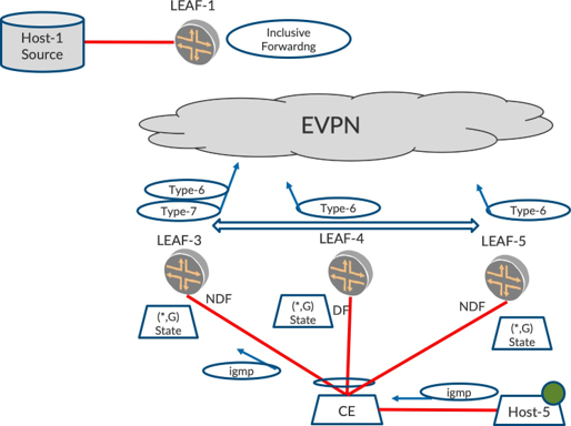
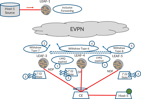
First let’s consider Figure 1, where LEAF-3, LEAF-4, and LEAF-5 are multihomed on an ESI.
Let’s suppose that LEAF-4 is the DF and LEAF-3 and LEAF-5 are Non-DFs. LEAF-2 and LEAF-6 are other single-homed PEs.
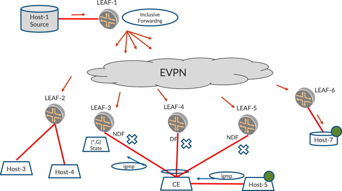
To describe the problem here, let’s consider that LEAF-1 is the Ingress and it performs Inclusive (IMET) forwarding, so therefore LEAF-1 floods the traffic to the core instead of selectively forwarding based on Type-6 SMET routes.
Suppose Host-5 is an IGMP Host interested in traffic for group G and hence sends IGMP (*,G) reports. The CE that is multihomed to the three LEAFs over an aggregated interface (AE) bundle may send the report to any one of the multihomed LEAFs. This is by virtue of the hashing that the CE performs on the packet based on the tuple consisting of Source IP, Destination IP, Source MAC, etc. Okay, let’s suppose that CE sends the IGMP (*,G) report to LEAF-3.
Upon receiving the (*,G) report, LEAF-3 creates an IGMP state for (*,G) such that if traffic for G arrives from the core or other access interfaces, it will forward the traffic to the CE and hence to Host-5. However, LEAF-3 is Non-DF per EVPN multihoming procedures in our example. Since the report did not reach LEAF-4 or LEAF-5, they do not create IGMP states for (*,G).
When LEAF-1 starts sending traffic for group G using Inclusive Forwarding, all the multihomed LEAFs will receive the traffic from core. By (CLASSICAL-DF-NDF) rules, only the DF forwards the traffic to access interface. Here, LEAF-4 is the DF.
However, since LEAF-4 does not have IGMP state for (*,G), LEAF-4 does not forward the traffic. LEAF-3, though it has the IGMP state for (*,G), does not forward the traffic because it is the non-DF on the multihomed link. LEAF-5, does not have the IGMP state as also it is an NDF.
Hence, we end up in a situation where neither of the multihomed PEs forward the traffic to Host-5, which is clearly undesirable.
If for some groups, by virtue of hash-tuple on CE, some IGMP reports reached LEAF-4, the DF, LEAF-4 will create a (*,G) state, and when traffic arrives from the core, LEAF-4, the DF, will forward traffic to CE and Rcv-1. This would hold in steady state.
There is still a problem, however. If LEAF-4 goes down or the multihomed interface on LEAF-4 goes down, LEAF-3 may be elected as the DF. Since LEAF-3 does not have IGMP (*,G) state, it will not forward the traffic. The refresh of the report may be sent to LEAF-5, the non-DF, and we may end up in the same state as before.
Multihoming Problem with Selective Forwarding
The problem with Inclusive Forwarding is that when the traffic from the EVPN core reaches all the multihomed peers, it does not get forwarded to the receiver because the LEAF-3 that has the IGMP state is the non-DF, and the LEAF-4 that is the DF does not have the IGMP state. Let’s review Figure 2.
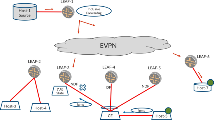
This is a problem with Selective Forwarding, too. If LEAF-3 and LEAF-6 originated the BGP Type-6 SMET route to reflect the state that it learned on the access, LEAF-1 will forward the multicast traffic only to LEAF-3 and LEAF-6. In this case, LEAF-3, though it has the IGMP state for group, does not forward the traffic to the receiver because it is the non-DF.
With Inclusive Forwarding, and no IGMP-snooping (in other words, BUM flooding procedures), this is not a problem because traffic will be flooded by LEAF-1 and will reach all Egress LEAF devices. The LEAF that is the DF will forward the traffic to the Host.
Since IGMP-Snooping and Selective (SMET) Forwarding mitigates the ‘flood everywhere’problem, it is worthwhile if we address this particular situation that arises due to IGMP-snooping and EVPN multihoming in the following sections on EVPN route types that can help solve this problem.
BGP Type-7 Join-Sync Route to Synchronize IGMP State in Multihoming PEs
To address the problem described here, we need the IGMP state for the group G to be synchronized among the multihomed PEs. If the IGMP state is synchronized among the multihomed PEs, the DF will have the (*,G) state and hence will forward the traffic towards the receivers.
The IGMP state for a particular group, learned over an ESI interface, is synchronized with other MH peers that host the same ESI by virtue of BGP Type-7 Join-Sync routes. Based on this exchange, the multihomed EVPN PEs can synchronize IGMP-state and install forwarding state for the group. By doing this, any of the relevant multihomed PEs will be in a position to forward the traffic on being elected the DF for that ESI.
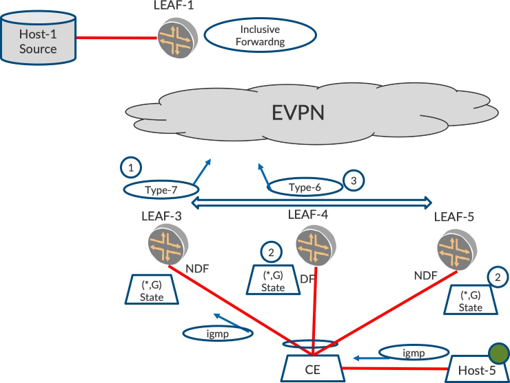
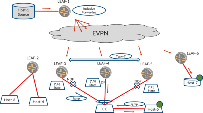
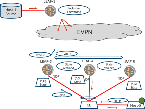
In Figure 3, the IGMP-report has reached LEAF-3. As part of event-[1], LEAF-3 originates a BGP Type-7 with the VLAN, group, and ESI information. This Type-7 route is imported only by LEAF-4 and LEAF-5 since these LEAFs host the ESI. Other LEAFs do not import this Type-7 route.
When LEAF-4 and LEAF-5 receive this Type-7 route, they build IGMP state for that particular group with the outgoing interface as the multihomed ESI interface (event-[2]). This way, the IGMP state for the group G is synchronized among the multihomed PEs.
By virtue of the IGMP state learned for the VLAN, the procedures described in EVPN Intra-VLAN Multicast with Optimization chapter will result in the multihomed PEs originating Type-6 routes for the group/VLAN. (event-[3]).
EVPN Type-7 NLRI Route
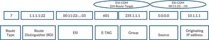
The Type-7 route consists of a route distinguisher, VLAN, Multicast Group and Source, ESI, and an originating IP. The route also carries the ESI value in an extended community. This helps to ensure that only those PEs that host the ESI import this Type-7 route.
The Type-7 route also carries a community called EVI-COM. This community identifies the EVPN instance on which the IGMP state has to be synchronized. The typical route target that is added in Type 2 and Type-6 routes is not added because we want the Type-7 routes to be imported only on those PEs that host the particular ESI in question.
Tracking of Type-7 Routes from Peers
An EVPN PE creates local IGMP state based on the incoming IGMP report on a particular ESI. It may be the case that there are multiple hosts behind the same ESI sending reports for a group. It may be that the reports landed on different multihomed peers. In this case, the PEs that received IGMP report from access-side ESI interface originate Type-7.
When an IGMP state timeout occurs on one LEAF, it should not delete the state immediately. Instead, it should check if there are any other remote Type-7 routes advertised for the same VLAN/Group/ESI/EVI. If so, the original Type-7 is withdrawn but the IGMP state is retained.
Type-7 Withdraw Semantics
A Type-7 route is withdrawn when the IGMP state has timed out (hosts haven’t refreshed the state on the ESI). A LEAF device, on receiving the Type-7 withdraw, should be careful in clearing the state. This Type-7 withdraw may be due to the ESI link being down or the originator node itself going down. The receiving PE has to ascertain that it is indeed a state timeout and then proceed to clear the state, or traffic drops will occur.
Non-DF to Originate Type-6 SMET Route for Better Convergence
Typically, upon receiving this Type-7 route only the DF needs to originate Type-6, since it is supposed to pull traffic from the core and forward the traffic to access. However, if the DF node fails or the ESI link on the DF fails, the new DF needs to be elected and then it has to originate the Type-6 SMET route. Also, the Ingress has to include the new DF in its outgoing PE list. These can result in considerable latency because BGP message exchange is involved.
This can be mitigated if the non-DF PEs also originate the Type-6 SMET route such that they pull the traffic from Ingress in steady state, but do not forward for access by virtue of being non-DF. Later, when the DF fails, the new DF, once elected, will have the traffic already arriving from the core. So, all the new DF needs to do is to forward the traffic to access. This results in considerable gain in convergence.
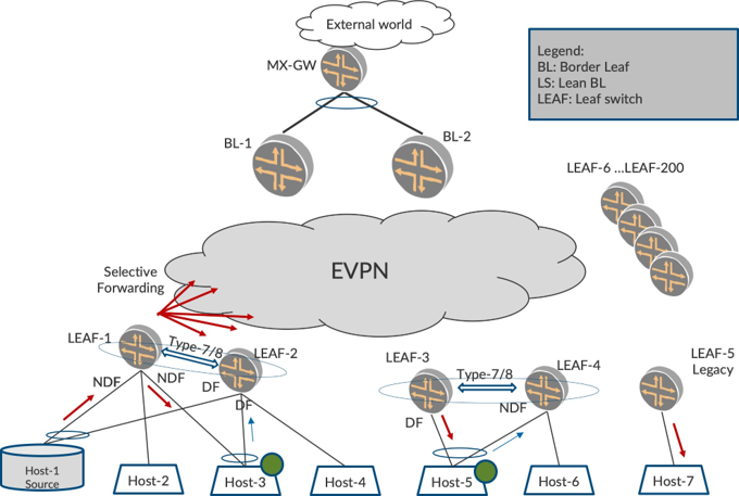
In Figure 5, all the multihomed PEs – LEAF-3, LEAF-4, and LEAF-5 – originate Type-6 SMET routes for the group. This results in LEAF-1 including all the multihomed PEs in its list. Thus, non-DF PEs receive traffic but do not forward it on the ESI interface, but they are ready to resume forwarding as soon as they get flipped to being DF.
Summary - IGMP Join-Sync and Multicast Forwarding
With this scheme, irrespective of where the report arrives on a multihomed segment, all the multihomed PEs of the ESI have IGMP state for the group G and are ready to forward with only the DF PE forwarding the traffic to the receiver. The Type-7 route carries information such that the receiving PE can create the appropriate IGMP state exactly for the relevant VLAN, EVI, and the ESI.
All the multihomed PEs on an ESI have the IGMP state for group G. At a minimum, the DF-PE for the ESI originates Type-6 routes, but to ensure better convergence, non-DF PEs also originate Type-6 and pull traffic. When traffic arrives on the core, the DF PE, since it has the IGMP state synchronized already with BGP Type-7 Join-Sync routes, forwards the traffic to the access ESI interface.
Also, the tracking of the peer Type-7s is imperative so that the IGMP synchronized state is coherent. The withdrawal of a Type-7 route should be carefully handled to determine the cause of the withdrawal and only then proceed with clearing/retaining the IGMP state.
Problem with IGMPv2 Leave
In earlier sections, we described how the IGMP (*,G) Report state is synchronized among the multihomed PEs. This section describes a problem wherein handling of an IGMP Leave message in a multihomed scenario needs special consideration.
IGMP Leave Primer
Just as an IGMP Report message for (*,G) is used to convey listener interest for a particular group G, the IGMP Leave message is used to convey withdrawal of listener interest for the group by the host.
When an IGMP Leave message is received by a switch, it needs to clear the IGMP (*,G) state that is used for forwarding such that traffic is no longer sent to the receivers. Before it clears the state, the switch needs to ensure that there are no other hosts interested in the group.
Towards this end, the switch sends out a last member query (LMQ) for group G to solicit any reports from other interested hosts. If the switch does not receive any report for the group G until a particular time period, LMQ Interval, the switch clears the state for (*,G). If any other host sends a report before the interval, the state is retained.
What Is Leave Latency?
Multicast applications are very sensitive to unwanted traffic. For instance, an IPTV Host may desire channel-1 by sending an IGMP report for group G1 and it may be receiving traffic. Say the bandwidth of the access interface has provision for traffic from one channel. When the user switches to channel-2, the host will withdraw interest for channel-1 by sending a Leave for group G1 and sending an IGMP report for group G2.
The switch has to process the Leave message for G1, check if other listeners exist, and if there are no other listeners, clear the state for G1 and stop forwarding to G1. Soon after, when the switch receives the IGMP report for group G2, it should create state for (*,G2) and start forwarding traffic for G2.
If for some reason the switch takes a longer time to clear state for G1, but creates for G2 and forwards traffic for both groups, the provisioned bandwidth may not be sufficient to carry both channels and may cause distortion on the IPTV host. Also, it may be that the host may not be capable of handling traffic for two groups.
Overall, it is imperative that the switch reacts soon enough on receiving a Leave message, does due diligence on LMQ, and clears state if no listeners exist. This delay in clearing state is referred to as Leave Latency and is an important factor for consideration in IPTV and stock-ticker applications.
If a Leave message is ‘lost on wire’ or not processed, the traffic will be forwarded to the listener. The switch, if it does not receive the IGMP reports periodically, say every 60 seconds, will clear the state after the IGMP-timeout interval, for example after 210 seconds.
So if a Leave message is lost or not handled, traffic will keep flowing until IGMP-timeout occurs. Leave Latency is given more careful consideration than the IGMP learning rate due to sensitivity of the IPTV hosts.
A Subtle Characteristic of the IGMPv2 Leave Message
IGMP Report messages have a source IP as the source of the host and the destination IP field as the Multicast Group address G that the host is interested in.
However, an IGMP Leave message has a destination IP field as 224.0.0.2, and the group that is desired to be withdrawn is present inside the payload of the Leave message. Historically, the reason has been the case with IGMPv2. Since IGMPv2 hosts are widely prevalent and have been working very well, it has remained this way.
Why is This Relevant to Optimized Multicast with Multihoming?
As discussed earlier, the CE will hash the incoming packets based on Source-IP, Destination IP, Source-MAC, etc. Since the destination IP field addresses of the Report are not the same as that of the Leave message, it so happens that the Report is sent to one multihomed EVPN PE, but the Leave message is sent to another multihomed EVPN PE.
IGMPv3
In the next section, we describe the challenge that arises due to the IGMPv2 Leave message having the destination address of 224.0.0.2. IGMPv3 is immune to this challenge because the IGMPv3 report and IGMPv3 Leave messages are carried in the payload and the destination address of both the Report and the Leave message is 224.0.0.22. Soon you will understand why this difference is relevant.
How Does This Cause a Problem in a Multihoming Scenario?
In Figure 7, the IGMP Report may be sent to LEAF-3. Later when Host-5 is not interested in traffic for group G, it sends out an IGMPv2 Leave for (*,G). This IGMP Leave for the same group may be sent to LEAF-5 because the destination IP address field for Leave is 224.0.0.2, while that of the IGMP report is the group itself. This is because the CE includes the destination IP address of the packet in calculating the hash tuple.
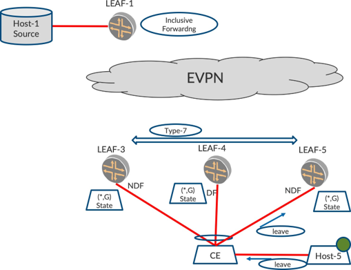
Let’s look at this in more detail. In Figure 7, LEAF-3 received the IGMP Report on the access interface, created IGMP (*,G) state (locally learned), and originated a Type-7 route. LEAF-4 and LEAF-5 imported the Type-7 and create an IGMP (*,G) state (remotely learned). So far so good.
Consider the scenario when the leave message reaches LEAF-5. What is the expected behavior here? An LMQ has to be sent towards CE to solicit for reports and if no reports arrive before a particular interval, the state has to be cleared from all the multihomed PEs, particularly the DF, so that traffic forwarding is stopped for group G.
What are our options? If we let existing IGMP Leave processing rules alone kick in, LEAF-5, on hearing Leave, will send an LMQ. What if there are no hosts interested anymore? LEAF-3, where the report initially landed, has not heard of the Leave. So LEAF-3 will not clear state for a good 210 seconds and the Type-7 will remain advertised for that long.
LEAF-5 will be in a flux where it has received a Leave message on the access, but it also has a remotely learned state. LEAF-5 cannot withdraw a Type-7 since it was not the originator of the Type-7 route in the first place, so the problem gets more involved. LEAF-5 retains the state since there is a remote Type-7 from LEAF-3. LEAF-4, and the DF, will retain the translated IGMP (*,G) state and keep forwarding for 210 seconds.
Overall, even though the host sent a Leave and it indeed reached the multihomed PE set, the Leave latency is still 210 seconds. This is clearly undesirable, multihoming and optimization features notwithstanding.
It gets more complicated when another host sends a report before the LMQ and this report lands on a different PE, say LEAF-4. Now LEAF-3 and LEAF-4 have locally learned states, while LEAF-5 has a remotely learned state and a Leave to handle. In this scenario, the states have to reconcile such that the state of IGMP (*,G) is retained on all PEs.
So it is imperative to address this Leave handling scenario as much as an IGMP-Join sync. This problem is hard to solve relying on existing IGMP Leave handling procedures alone because there is a need to synchronize the Leave. Also, while IGMP Join (*,G) is a state that can be translated to BGP routes and exchanged, the Leave message is indeed an event and not a state.
With Leave messages, the earlier learned state is cleared. Hence, this appears as an event for the LEAF that got a Leave. Traditionally BGP notifies ADD/DELETE/UPDATE of a state. This Leave message is supposed to result in withdrawal of BGP route and state, but the fact that the Leave arrives on the non-originator of the state makes it difficult to convey the withdrawal of the state.
This event also has to be conveyed among the multihomed PEs such that they are in sync with the latest activity on the access ESI interface for the group to ensure Leave Latency is within acceptable limits. Different combinations also have to be able to work without much Leave Latency, the most common being (i) a IGMP Join followed by a Leave, or (ii), a Join followed by a Leave and followed by another Join, etc.
This problem is addressed by introducing another BGP route called Type-8 Leave-Sync route such that the multihomed PEs are in sync with each other about the state for the group (*,G).
BGP Type-8 Leave-Sync Route to Reconcile IGMP State
To address the problem described in the preceding section, let’s explore the approach. The objective of the solution is the below:
When a Join is received from access, the IGMP join state should be synced between all multihomed PEs.
When a Leave is received from access on a multihomed setup, the LMQ timer should be started on all multihomed peers and the LMQ should be sent on the access by the DF.
If no Join is received until the LMQ timer expires, then, the IGMP state should be deleted on all multihomed peers.
If an override IGMP join is received before the LMQ timer expires, then, the IGMP state should be retained on all multihomed peers.
In Figure 8, a Join was received on the access from Host-5 on LEAF-3 and state was synchronized between the multihomed peers using a Type-7 Join-Sync route. Now, let’s say, Host-5 sends an IGMP leave and this IGMP leave arrives on LEAF-5 (event-[1]).
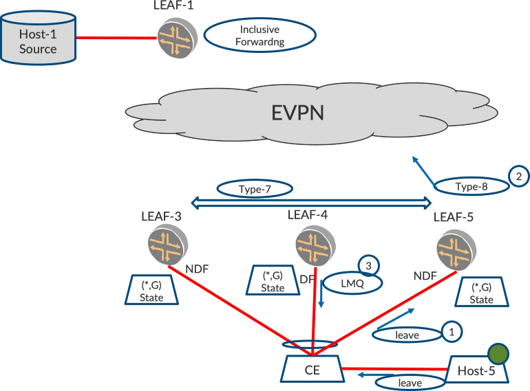
Upon receiving a Leave, LEAF-5 originates a Type-8 route (event-[2]) which has the NLRI fields the same as that of a Type-7 (VLAN, ESI, Group, source, origin IP, etc.). The trigger for the origination of Type-8 is a Leave message but there is no trigger for withdrawal of this route. Thus LEAF-5 starts a ‘Leave-Sent-Timer’ to withdraw the route once its purpose of synchronizing Leave is served.
Other multihomed peers, LEAF-3 and LEAF-4, receive the Type-8. Based upon this, all the multihomed PEs look to send out the send LMQ and start the LMQ timer. Since this LMQ is a multicast message, only the DF will send out the LMQ on the ESI. (event-[3]).
Two events can occur with this LMQ timer.
Event-A: No Joins received on the LAN for this group before LMQ expires.
Event-B: Join received on the LAN for this group before LMQ expires.
Event-A: No Joins Received on LAN in Response to LMQ (Join + Leave)
In Figure 9, after sending LMQ and starting the LMQ timer, the multihomed Peers wait to see if any IGMP report is refreshed for that group. If no reports were received and the LMQ timer expires (event-[1]).
In Figure 9, the originator of the Type-7 withdraws its Type-7 route (event-[2]). On the Type-7 remote route withdrawal, the multihomed peers delete the IGMP state, thus stopping forwarding traffic to the access. (event-[3]).
Based on the local state going away, if there is no other interested access interface in the VLAN for that group, the multihomed devices withdraw their earlier originated Type-6 route. (event-[4]).
With the Type-8 route, the states are now cleared and LEAF-5 withdraws its Type-8 route (event-[5]) to avoid any stale lingering of Type-8, thus clearing all the states for that flow.
Event-B: Join Received Before LMQ Timer Expires (Join + Leave + Join)
In Figure 10, after sending LMQ and starting the LMQ timer, the multihomed Peers wait for some time to see if any IGMP report is refreshed for that group. Suppose that before the LMQ timer expires another host sends an IGMP report on the LAN. This report may arrive on the earlier originator of Type-7, LEAF-3, or on a new originator, say, LEAF-4.
If Refresh Report Arrived on LEAF-3, the Earlier Type-7 Originator
LEAF-3, on receiving the refreshed report on access, stops its LMQ timer. It does _not withdraw its Type-7 route. Later, on other multihomed peers, when the LMQ timer expires they check if there is a remote Type-7 for the group. Since there is a remote Type-7 for the group, the multihomed peers will retain the IGMP state and continue forwarding the traffic.
If Refresh Report Arrived on LEAF-4, Which Is Not the Earlier Type-7 Originator
On receiving the refreshed report on access, LEAF-4 stops its LMQ timer. It also originates its Type-7 route, which gets synced to other multihomed peers. Once they’ve received the remote Type-7 route, other multihomed peers import this into their table.
When LMQ expires (since its report was not refreshed), the originated Type-7 on LEAF-3 is withdrawn. However, since there is at least one other remote Type-7 (from LEAF-4), LEAF-3 retains the IGMP state.
And on LEAF-5, when LMQ expires, there is at least one remote Type-7 (from LEAF-4). So LEAF-5 also retains the IGMP state.
Putting It All Together for Optimized Multicast
Figure 11 repeats our original topology to bring back the big picture. Host-3 and Host-5, the multihomed hosts, are interested in traffic. The multihomed LEAF devices synchronize the IGMP state and ensure correct forwarding occurs. The Traffic Verification section of this chapter illustrates this scenario in detail.
Chapter Summary
This chapter explored the nuances associated with optimizing multicast in multihomed topologies. To accomplish this, it detailed how IGMP reports received on an ESI link are synchronized amongst the multihomed peers that host the ESI. It also examined the origination of the Type-6 route by the multihomed peers for the sake of convergence.
Also of interest was the challenge that arises by virtue of the IGMP Leave message reaching a PE different from the one where IGMP Report was received, and how this is addressed by Type-8 route.
With Types-6/7/8, we have ensured multicast optimization in the core and access. We have also addressed the multihoming challenges. In Assisted Replication with SMET chapter we will explore how the combination of these optimizations with AR brings in the best of both worlds.
Configuration
Figure 12 depicts the reference topology.
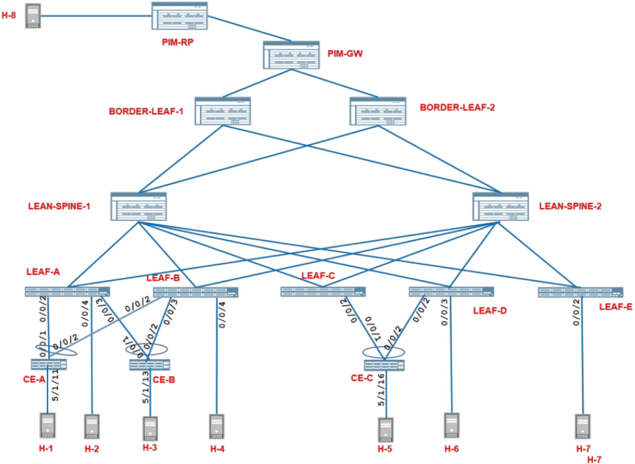
Configuration
The configurations done in EVPN Intra-VLAN Multicast with Optimization chapter are sufficient for this section.
Traffic Verification
Keeping the existing traffic that we started in EVPN Intra-VLAN Multicast with Optimization chapter from Host-1, and the receiver on Host-6; on Host-3, that is multihomed to LEAF-1 and LEAF-2. Let’s now start a receiver for the multicast group, 225.1.1.1 on VLAN-101.
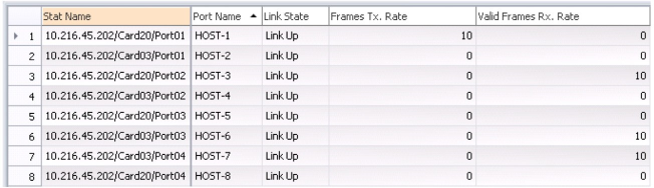
From the RT statistics in Figure 13, you can see that the traffic sent by Host-1 at 10 pps is now being received by the interested single-homed receivers: Host-6, the interested multihomed receiver Host-3, and the legacy device, Host-7 in VLAN-101.
Multicast Traffic Outputs - LEAF-1
As before, the load balanced multicast traffic arrives on access interface, ae0 on LEAF-1. LEAF-1 now forwards this traffic on its access interface ae1.0, on which it has learned an interested IGMP receiver. Recall that the SRC-LOCAL-BIAS rules allow LEAF-1 to forward the traffic on ae1.0 irrespective of the DF/ NDF status:
lab@LEAF-1> monitor interface traffic detail
Interface Link Input packets (pps) Output packets (pps) Description
…
xe-0/0/4   Up       0         (0)      2564        (0)    TO Host-2
…
ae0        Up     14467      (10)        0         (0)      TO CE-1
ae1        Up       0         (0)      7260       (10)      TO CE-2
…
The multicast traffic is forwarded on the VTEPs towards Border-LEAF PEs (101.101.101.101 and 102.102.102.102) and LEAF-5 (109.109.109.109). The traffic is also sent on the VTEPs towards LEAF-2 (106.106.106.106) and LEAF-4 (108.108.108.108) since they have interested receivers.
LEAF-3 (107.107.107.107) that does not have any interested receivers is still spared of the traffic:
lab@LEAF-1> show interfaces vtep extensive | grep “VXLAN Endpoint Type: Remote|Output packets.*pps”
VXLAN Endpoint Type: Remote, VXLAN Endpoint Address: 106.106.106.106…
  Output packets:	7238	9 pps
VXLAN Endpoint Type: Remote, VXLAN Endpoint Address: 101.101.101.101…
  Output packets:	14854	9 pps
VXLAN Endpoint Type: Remote, VXLAN Endpoint Address: 108.108.108.108…
  Output packets:	10638	10 pps
VXLAN Endpoint Type: Remote, VXLAN Endpoint Address: 107.107.107.107…
  Output packets:	4719	0 pps
VXLAN Endpoint Type: Remote, VXLAN Endpoint Address: 109.109.109.109…
  Output packets:	10144	10 pps
VXLAN Endpoint Type: Remote, VXLAN Endpoint Address: 102.102.102.102…
  Output packets:	14855	9 pps
Multicast Traffic Outputs - LEAF-2
The access side IGMP-snooping functionality ensures that the multicast traffic arriving on LEAF-2 is not forwarded on the single-homed interface, xe-0/0/4.0, or on ae0.0, which does not have a receiver.
Though the multihomed access interface ae1.0 has a receiver, recall that the DST-LOCAL-BIAS rules ensure that the multicast traffic is not forwarded on this interface. This ensures that there is no traffic duplication towards the multihomed host, Host-2:
lab@LEAF-2> monitor interface traffic detail
Interface Link Input packets (pps) Output packets (pps) Description
…
xe-0/0/4   Up       0         (0)       247        (0)    TO Host-4
ae0        Up      553        (0)       213        (0)      TO CE-1
ae1        Up       0         (0)       208        (0)      TO CE-2
…
Multicast Traffic Outputs - LEAF-4, LEAF-5, and BL Devices
There is no change in the traffic forwarding behavior on these devices. The outputs are therefore omitted for the sake of brevity.
Detailed Control Plane Verification
Verification of EVPN Join-Sync with Multihomed Receivers
Since Host-3 is multihomed, the IGMP report may reach either LEAF-1 or LEAF-2. In our case, it reaches LEAF-1.
Let’s verify that on LEAF-1, the IGMP group membership has been learned on VLAN-101 interface ae1.0 by snooping the IGMP reports:
lab@LEAF-1> show igmp snooping membership VLAN VLAN-101 225.1.1.1
Instance: default-switch
VLAN: VLAN-101
…
Interface: ae1.0, Groups: 1
    Group: 225.1.1.1
        Group mode: Exclude
        Source: 0.0.0.0
        Last reported by: 18.18.18.40
        Group timeout:     226 Type: Dynamic
lab@LEAF-1> show igmp snooping evpn database VLAN VLAN-101 225.1.1.1 interface ae1.0
Instance: default-switch
  Bridge-Domain: VLAN-101, VN Identifier: 101
        Group IP: 225.1.1.1, Source IP: 0.0.0.0
            Core NH: 131073
            Access OIF Count: 1
                  Interface Local Remote
                  ae1.0       1        0
lab@LEAF-1> show evpn igmp-snooping database l2-domain-id 101 group 225.1.1.1 extensive
Instance: default-switch
  VN Identifier: 101
        Group IP: 225.1.1.1, Source IP: 0.0.0.0
            Access OIF Count: 1
            Interface              ESI               Local Remote
            ae1.0      00:22:22:22:22:22:22:22:22:22   1      0
Verify that LEAF-1 has originated an EVPN Type 7 Join-Sync route corresponding to this locally learned IGMP group membership on the multihomed interface ae1.0:
lab@LEAF-1> show route table    default_evpn	evpn.0 evpn-ethernet-tag-id 101 match-prefix 7:* extensive
    default_evpn	evpn.0: 7 destinations, 7 routes (7 active, 0 holddown, 0 hidden)
7:105.105.105.105:1::222222222222222222::101::225.1.1.1::105.105.105.105/600 (1 entry, 1 announced)
*EVPN Preference: 170
…
Protocol next hop: 105.105.105.105
…
Communities: encapsulation:vxlan(0x8) es-import-target:22-22-22-22-22-22 evi-rt:1:1
…
IGMP flags: 0xa
Verify that LEAF-2 has processed this EVPN Type 7 Join-Sync route from LEAF-1 and learned the remote membership on ae1.0:
lab@LEAF-2> show route table __default_evpn__.evpn.0 evpn-ethernet-tag-id 101 matchprefix
7:* extensive
__default_evpn__.evpn.0: 7 destinations, 7 routes (7 active, 0 holddown, 0 hidden)
7:105.105.105.105:1::222222222222222222::101::225.1.1.1::105.105.105.105/600 (1 entry, 1 announced)
        *BGP    Preference: 170/-101
                Route Distinguisher: 105.105.105.105:1
…
                Source: 105.105.105.105
                Protocol next hop: 105.105.105.105
…
                Communities: encapsulation:vxlan(0x8) es-import-target:22-22-22-22-22-22 evi-rt:1:1
                Import Accepted
                IGMP flags: 0xa
…

lab@LEAF-2> show evpn igmp-snooping database l2-domain-id 101 group 225.1.1.1 extensive
Instance: default-switch
  VN Identifier: 101
        Group IP: 225.1.1.1, Source IP: 0.0.0.0
            Access OIF Count: 1
            Interface            ESI                  Local Remote
            ae1.0     00:22:22:22:22:22:22:22:22:22     0        1

lab@LEAF-2> show igmp snooping evpn database VLAN VLAN-101 225.1.1.1 interface ae1.0
Instance: default-switch
  Bridge-Domain: VLAN-101, VN Identifier: 101
        Group IP: 225.1.1.1, Source IP: 0.0.0.0
            Core NH: 131082
            Access OIF Count: 1
            Interface Local Remote
            ae1.0       0      1
Verification of EVPN IGMP Proxy State with Multihomed Receivers
Verify that LEAF-2, having learned local IGMP membership for the group 225.1.1.1, via EVPN Type 7 Join-Sync routes, builds local EVPN IGMP-proxy state and originates a Type 6 IGMP Proxy route to notify remote PEs of its interest in receiving multicast traffic for the group.
Note that LEAF-2 would also learn remote proxy states based on the Type 6 originated by LEAF-4 (in EVPN Intra-VLAN Multicast with Optimization chapter) and LEAF-1 (now):
lab@LEAF-2> show igmp snooping evpn proxy VLAN VLAN-101 225.1.1.1
Instance: default-switch
  Bridge-Domain: VLAN-101, VN Identifier: 101
        Group     Source  Local Remote
        225.1.1.1 0.0.0.0   1        1

lab@LEAF-2> show evpn igmp-snooping proxy l2-domain-id 101 group 225.1.1.1 extensive
Instance: default-switch
  VN Identifier: 101
    Group     Source  Local Remote Corenh Flood
    225.1.1.1 0.0.0.0   1     2    131089     0

lab@LEAF-2> show route table default-switch.evpn.0 evpn-ethernet-tag-id 101 matchprefix
6:* extensive protocol evpn
default-switch.evpn.0: 84 destinations, 84 routes (84 active, 0 holddown, 0 hidden)
6:106.106.106.106:1::101::225.1.1.1::106.106.106.106/520 (1 entry, 1 announced)
        *EVPN   Preference: 170
…
                Protocol next hop: 106.106.106.106
…
                Communities: encapsulation:vxlan(0x8)
                IGMP flags: 0xa
Similarly, due to its local IGMP join, LEAF-1 would also originate a Type 6 route for the group 225.1.1.1. LEAF-1 would also learn remote proxy states based on the Type 6 originated by LEAF-4 (in EVPN Intra-VLAN Multicast with Optimization chapter) and LEAF-2 (now):
lab@LEAF-1> show igmp snooping evpn proxy VLAN VLAN-101 225.1.1.1
Instance: default-switch
  Bridge-Domain: VLAN-101, VN Identifier: 101
        Group     Source     Local Remote
        225.1.1.1 0.0.0.0      1        1

lab@LEAF-1> show evpn igmp-snooping proxy l2-domain-id 101 group 225.1.1.1 extensive
Instance: default-switch
  VN Identifier: 101
    Group     Source     Local Remote Corenh Flood
    225.1.1.1 0.0.0.0      1      2   131088     0

lab@LEAF-1> show route table default-switch.evpn.0 evpn-ethernet-tag-id 101 matchprefix
6:* extensive protocol evpn
default-switch.evpn.0: 84 destinations, 84 routes (84 active, 0 holddown, 0 hidden)
6:105.105.105.105:1::101::225.1.1.1::105.105.105.105/520 (1 entry, 1 announced)
        *EVPN   Preference: 170
…
                Protocol next hop: 105.105.105.105
…
                Communities: encapsulation:vxlan(0x8)
                IGMP flags: 0xa
Verify that all remote PEs process the EVPN Type 6 routes and learn LEAF-1 and LEAF-2 as interested remote EVPN receivers for the group. We did this in EVPN Intra-VLAN Multicast with Optimization chapter for the Type-6 from LEAF-4. So this is left as an exercise for the reader.
Verification of Multicast Forwarding State
Verify that the multicast forwarding state created for the group 225.1.1.1 in LEAF-1 and LEAF-2 now includes the interested multihomed interface ae1.0:
lab@LEAF-1> show multicast snooping route extensive VLAN VLAN-101 group 225.1.1.1
…
Group: 225.1.1.1/32
	Source: *
	VLAN: VLAN-101
	Mesh-group: all_ces
		Downstream interface list:
		evpn-core-nh -(131088) ae1.0 -(1715)
…
lab@LEAF-2> show multicast snooping route extensive VLAN VLAN-101 group 225.1.1.1
…
Group: 225.1.1.1/32
	Source: *
	VLAN: VLAN-101
	Mesh-group: all_ces
		Downstream interface list:
		evpn-core-nh -(131089) ae1.0 -(1715)
…
Verify that on LEAF-1, in addition to LEAF-4 (vtep.32771), now LEAF-2 (vtep.32769) has also been added to the EVPN core next hop for the group 225.1.1.1. Note that in addition, BL-1 (vtep.32770), BL-2 (vtep.32774), and LEAF-5 (vtep.32773), will also be present in the EVPN core next hop for the group:
lab@LEAF-1> show evpn igmp-snooping proxy l2-domain-id 101 group 225.1.1.1 extensive
Instance: default-switch
  VN Identifier: 101
    Group     Source   Local Remote Corenh Flood
    225.1.1.1 0.0.0.0    1      2   131088     0
lab@LEAF-1> show evpn multicast-snooping next-hops 131088 detail
…
ID       Refcount KRefcount Downstream interface Addr
131088      3         1     vtep.32769-(1751)
                            vtep.32770-(1756)
                            vtep.32771-(1761)
                            vtep.32773-(1764)
                            vtep.32774-(1765)
Verify that the multicast forwarding state created for the group 225.1.1.1 has been updated to now include the EVPN core next hop seen above:
lab@LEAF-1> show multicast snooping route extensive VLAN VLAN-101 group 225.1.1.1
…
Group: 225.1.1.1/32
	Source: *
	VLAN: VLAN-101
	Mesh-group: all_ces
		Downstream interface list:
		evpn-core-nh -(131088) ae1.0 -(1715)
…