ON THIS PAGE
EVPN Intra-VLAN Multicast with Optimization
EVPN Intra-VLAN Multicast Without Optimization chapter and Assisted Replication chapter explored EVPN Multicast procedures where L2-switched traffic was 'flooded everywhere’. This flooding to remote PEs that don’t have any listeners behind them, and the PEs flooding traffic onto all the access interfaces, even if there are no listeners, is clearly undesirable.
One downside to this unrestrained flooding is that all the LEAF devices are burdened with processing traffic. That is not useful. Some LEAF devices may be low-end devices or may even be virtual LEAF devices. If these devices are subjected to heavy multicast traffic, they will choke other traffic applications and degrade performance.
Also, redundant traffic that gets sent on access interfaces may affect the link utilization, degrading other genuine flows for which there are listeners. The flooding of traffic onto EVPN core with Ingress Replication to PEs that do not have listeners behind them results in core bandwidth consumption and an excess load on the Ingress LEAF towards creating multiple redundant copies.
In this chapter we describe mechanisms that ensure traffic is forwarded only on to those access interfaces where there is listener interest. We also describe procedures where the traffic is Ingress Replicated over the EVPN core to only those remote EVPN PEs that have expressed listener interest. Let’s explore the procedures that will help mitigate the unbridled flooding of multicast traffic everywhere. Towards this end, we introduce IGMP-snooping, Selective Multicast Forwarding, BGP Type-6 SMET Route, and more.
These procedures help optimize multicast forwarding in the DC Fabric. Care is taken to ensure that multicast traffic is forwarded only towards those PEs or access interfaces that have listener interest for a particular flow. As a result, there is a substantial gain in terms of link and core bandwidth utilization, reduction in Ingress Replication Load, and reduction in Egress processing load.
When these optimization techniques are used along with AR (described in an earlier chapter), we get the benefits of optimization and also the transfer of replication load to the AR-Replicator.
Due to legacy devices, in some cases it may not be possible to have this optimization capability on all LEAFs. In this chapter we describe the procedures that help to accommodate such devices and ensure multicast forwarding occurs in the right manner.
EVPN with IGMP-Snooping
Multicast optimization on a L2-switch is described as such because EVPN as a technology enables stretching the L2-domain over remote devices. An EVPN LEAF device plays the role of an L2-switch on its access interfaces. With IGMP snooping enabled on an EVPN LEAF device (see Figure 1) the multicast traffic is sent only on those interfaces that have listeners behind them.
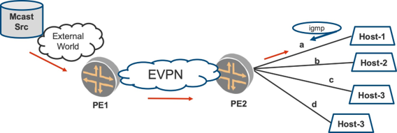
Let’s say that in Figure 1, PE2 is configured with EVPN and IGMP-snooping. When multicast traffic sent from the Mcast Source reaches PE2 over EVPN, PE2 should forward multicast traffic only to interface ‘a’, since it has received an IGMP Report (listener interest) only from interface ‘a’.
Traffic is not flooded onto other access interfaces b, c, and d.
PE2 is an EVPN device that is enabled with IGMP-snooping on the bridge-domain. PE2 snoops membership information on the access interface and tracks the association. When multicast traffic arrives from core or from access interface, the traffic is flooded only on those interfaces where the IGMP state is learned.
Primer on IGMP-Snooping
In this section, let’s explore the L2 multicast optimization techniques that have been widely deployed in the switching world for more than a decade. This multicast optimization on the access interfaces is achieved with IGMP Snooping. This has been used extensively in the L2-switching world where there is a need to forward traffic onto only those interfaces with listeners behind them.
In a typical L2 switching environment, multicast traffic is always forwarded on all interfaces. In Figure 2’s topology, the switch has five access interfaces: a, b, c, d, and x. Say there is no L2-switched multicast optimization configured on the switch.
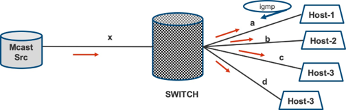
Let’s assume Host1 alone is interested in traffic for group G and sends an IGMP report for (*,G). IGMP is a protocol used by hosts and adjacent routers/switches to establish multicast group memberships. With an IGMP report for group G, the host expresses listener interest for group G to the nearest switch/router on the LAN.
On a switch without multicast optimization, when the source starts sending traffic on x for group G, the switch will flood the traffic onto all four interfaces – a, b, c, and d – even though Hosts 2, 3, and 4 are not interested in that group.
In a different case, when there are no listeners for the group and the source sends traffic, the switch will still flood the traffic onto all four interfaces: a, b, c, and d. This is clearly undesirable.
Now let’s say the switch is configured with IGMP snooping. With IGMP snooping, when an IGMP Report/ Join is received (snooped) on interface a, the switch will snoop the (*,G) report and create an associated IGMP state for G with interface a.
When multicast traffic arrives on interface ‘x’ for group G, the switch will forward the traffic only to interface ‘a’ based on the (*,G) state that it maintained for interface ‘a’. (ACCESS-SNOOP) . Thus, the unnecessary flooding of traffic onto interfaces b, c, and d is avoided.
Also, if there are no IGMP reports from any of the interfaces (a,b,c,d) and if traffic arrives on interface ‘x’, with IGMP snooping enabled, the switch will not forward traffic to any of the interfaces (a,b,c,d).
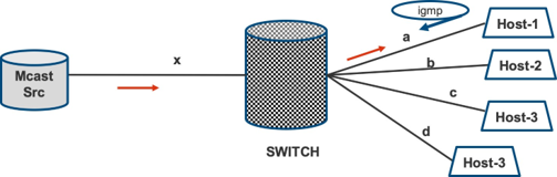
Typically the switch will have several ports. With IGMP-snooping enabled on the switch, the bandwidth usage on the interfaces is considerably reduced. Also, the hosts that are not interested in the group are not burdened with unnecessary traffic. Needless to say, the replication load of the switch to create redundant copies is also reduced by virtue of IGMP-snooping.
The switch periodically sends out ‘IGMP General Queries’ to solicit listener interest by way of IGMP reports from hosts. When a host is no longer interested in the particular flow G, the host sends out an IGMP Leave message. Upon receiving the IGMP Leave message, the switch sends out a ‘Group Specific Query’ for the particular group G, to solicit if there are still other hosts interested in group G.
Towards this end, the switch starts a timer called ‘Last Membership Query’. Once the timer expires, the switch is now sure of the absence of listener interest on the interface. Based on this, the switch removes the IGMP state for the group for the interface.
Selective Multicast Forwarding Towards the Core
So far we have discussed multicast traffic optimization on the access side. It is imperative that the traffic that is flooded onto the core using Ingress Replication is optimized, too, such that only those PEs that have listeners behind them actually receive traffic. This is referred to as EVPN Selective Multicast Forwarding.
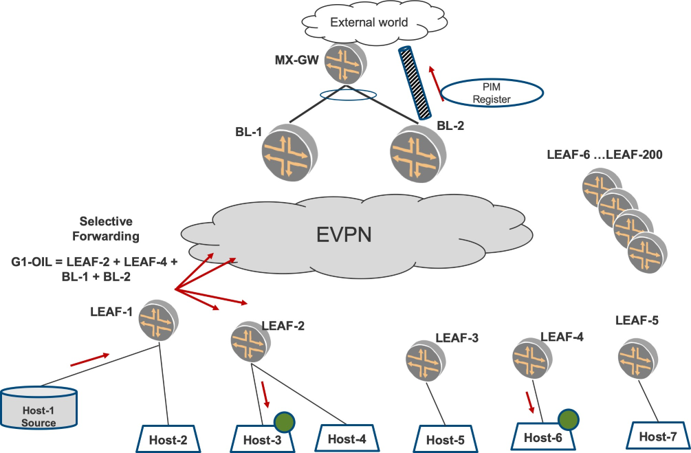
Consider Figure 4 where all the LEAF devices have VLAN VLAN-101/VNI-101 enabled. LEAF-3 does not have a listener for group G, behind it. But what if there were hundreds of LEAFs like LEAF-3 that do not have listeners behind them for the group G?
If the Ingress PE, LEAF-1 in Figure 4, excludes these LEAFs in its Ingress Replication Flood List, then we would have achieved Selective Multicast Forwarding for group G. This results in conserving core bandwidth and also in exempting the LEAFs that don’t have listeners behind them from traffic processing overhead.
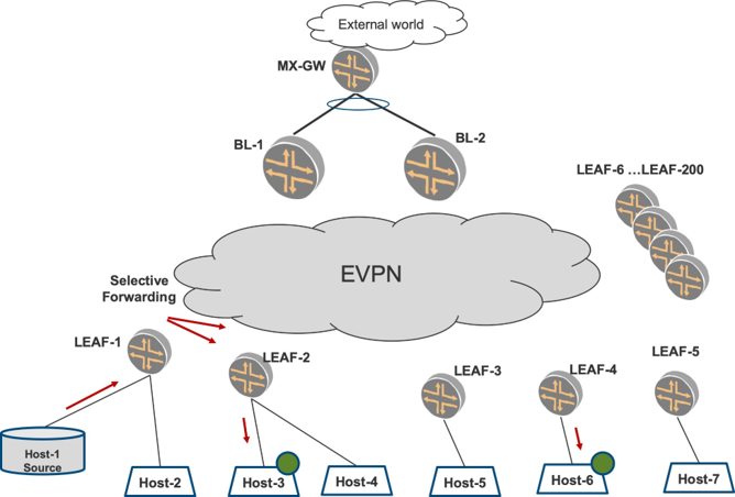
With selective forwarding, in Figure 4 LEAF-1 will L2-switch the traffic from the source only to LEAF-2 and LEAF-4. Further, LEAF-2 will flood the multicast traffic only on those access interfaces where there are listeners (by virtue of IGMP-snooping on access (ACCESS-SNOOP)). Therefore, LEAF-2 sends the traffic only to Host-3 but not towards Host-4. LEAF-4 floods the traffic only to Host-6. No other access interfaces carry the traffic. Also, no other LEAF devices receive the traffic over the core.
Three kinds of benefits accrue:
LEAF-1’s Ingress Replication load is considerably reduced, for example, replicating traffic to only two LEAFs as against sending to 200 LEAFs.
Core bandwidth utilization is considerably reduced. Each superfluous replicated packet would have had to go to non-interested LEAF devices only to be dropped.
LEAF-3 and other such LEAFs that do not have listeners are spared from processing this unnecessary traffic, thereby freeing them up for other tasks.
When a host behind a LEAF Joins a group G, the Ingress sends the traffic for group G to the LEAF. Similarly, when the host sends out IGMP Leave for group G, the Ingress stops sending the traffic for group G to the LEAF. In other words, the Ingress forwards traffic for a group G to a LEAF only as long as there is a remote listener interest for the group behind that LEAF
Basic Procedures for Selective Multicast Forwarding
Now let’s describe the mechanism with which Selective Multicast Forwarding is accomplished. As described in the IGMP-snooping Primer section at the beginning of this chapter, the EVPN LEAF devices snoop the reports and keep the IGMP state associated with the interface.
BGP Type-6 SMET (Selective Multicast Ethernet Tag) Route
The EVPN LEAF device, when it receives a report for a group G1 from any of the access interfaces on a VLAN, will originate a BGP EVPN Type-6 NLRI route for G1. This Type-6 route contains Route-Distinguisher, Ethernet-Tag, Multicast Group address, and originating IP address as shown in Figure 5.
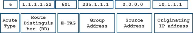
This route also carries the RT-target community that identifies the EVPN instance such that only those EVPN PEs that host the relevant EVPN instance will import this route.
The E-Tag field carries the VLAN for which listener interest for the Group address is relevant. For a group G in a VLAN V-101, there may be few or several LEAF devices that have listener interest. Each of these LEAF devices will originate this Type-6 route. Since their Route Distinguishers and Originating IP address will be different, the Ingress will be able to clearly identify the specific interested LEAF devices and build the Selective Floodlist accordingly.
The term outgoing interface list (OIL) is traditionally used to refer to the list interfaces on which multicast traffic for a specific group G1 has to be sent out. In our discussions, the OIL for a group G1 on an Ingress will be the VTEP interfaces that point to the specific interested LEAF devices for that group.
This BGP Type-6 route can be considered as the EVPN equivalent of an IGMP report received on the access, therefore this Type-6 route is the equivalent of IGMP (*,G1) report in the EVPN core.
In Figure 6, LEAF-2, when it receives the IGMP (*,G1) report from Host-3 on VLAN-101 from access, will originate an EVPN Type-6 route for VLAN VLAN-101 and group G1. Similarly, LEAF-4 will also originate a Type-6 for group G1 on VLAN-101.
It is worth noting that LEAF-2 will not forward the IGMP-report into the core as it has already signaled the listener interest with Type-6. This Type-6 route also helps in avoiding unnecessary IGMP reports being refreshed in the core.
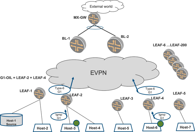
LEAF-1 will import the Type-6 routes for group G1 from LEAF-2 and LEAF-4. Further, LEAF-1 will install a multicast snooping forwarding entry specifically for G1 that includes only LEAF-2 and LEAF-4 in its OIL. When traffic arrives for group G1 from the source, the traffic will hit this specific multicast forwarding entry for G1 and will be Ingress Replicated selectively to only LEAF-2 and LEAF-4 alone.
An Example with Two Different Groups G1 and G2
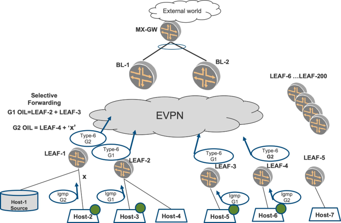
Figure 7 depicts hosts that are interested in two different groups, say G1 and G2. The hosts Host-3 and Host-5 are interested in group G1, while Host-2 and Host-6 are interested in group G2. The respective Type-6 routes for group G1 are originated by LEAF-2 and LEAF-3, while for group G2, by LEAF-1 and LEAF-4.
From Ingress PE LEAF-1’s point-of-view, the OIL for G2 will include LEAF-4 and also access interface ‘x’ towards Host-2. The Ingress PE will build an OIL that has a VTEP interface towards LEAF-4 and also an access interface ‘x’ towards Host-2. Traffic for group G2 will not be sent to any of the 200 LEAF devices except LEAF-4 and onto ‘x’ towards Host-2. This is a significant optimization vis-à-vis the EVPN Intra-VLAN Multicast Without Optimization chapter sections.
Suppose there is a group G3 (not shown in Figure 7) for which there are no listeners anywhere in the fab ric. The Ingress, LEAF-1, does not receive any Type-6 routes for G3 and hence does not install a specific forwarding entry for G3. When a source sends traffic for G3 towards LEAF-1, then, LEAF-1 will not forward the traffic for G3 towards the core at all.
Often there is high volume multicast traffic that is sent for several groups but there are no active listeners for such groups. With the mechanism of Selective Multicast Forwarding, the high-volume traffic is not sent towards the core to any of the 200 LEAF devices for such groups, thus saving considerable core bandwidth.
BGP Type-6 NRLI SMET Route and Selective Multicast Forwarding
The EVPN Type-3 route is also referred to as an inclusive multicast Ethernet tag (IMET) route because based on this route traffic is forwarded in an inclusive manner, for example, ‘flooded’ to the LEAF devices irrespective of listener interest.
The EVPN Type-6 route is referred to as a Selective Multicast Ethernet Tag (SMET) route.
The subtle usage of terms here does make a difference:
SMET Route: This refers to the BGP Type-6 NLRI route that the EVPN LEAF devices originate when there is a listener interest for a particular group G in a particular VLAN.
Selective Multicast (SMET) Forwarding (sometimes called SMET Forwarding): This is the capability of Ingress EVPN PE that builds a specific multicast snooping forwarding entry for a group G1 and the OIL with specific interested the LEAF devices’ VTEPs, based on the remote EVPN Type-6 routes that it has heard from the LEAF devices. (CORE-SMET-FWD)
IGMP-snooping and Selective (SMET) Forwarding are techniques for optimizing multicast traffic. For optimized multicast forwarding in the core to work well, it is imperative that both the above ‘a’ and ‘b’ are supported on the appropriate devices. For example, a EVPN device that is connected to listeners should support at least SMET Route capability. An EVPN device that is Ingress should support both SMET Route capability and Selective Multicast (SMET) Forwarding paradigm.
Since the Type-6 routes get sent from the LEAF to Spine, periodic refreshes of the IGMP reports over the core are avoided. On the access interface, when the listeners send IGMP Leave for a group G, the LEAF will send out a Group Specific Query to ensure no other listeners exist for that group. Once the LEAF has affirmed that listener interest has gone away, it withdraws the advertised Type-6 route. This results in the Ingress updating its OIL with the remote LEAF removed from the list.
An IGMP-snooping state for a group on access side, tracks each L2-interface on which a listener report for G is received. It is worthwhile to mention here that Type-6 for a group G is representative of the listener interest on that VLAN on the LEAF.
As long as there is at least one access L2 interface where there is listener interest, a Type-6 route for group G is originated. Also, when there is no access L2 interface in the VLAN on which there is listener interest for group G, the Type-6 for group G on that VLAN is withdrawn.
So far, we have described only single-homed scenarios where optimized forwarding is illustrated. With multihoming there are challenges that are explored in EVPN Intra-Multicast Optimization with Multihoming chapter.
EVPN Multicast Flags Community: SMET Feature Capability Exchange
Many times, in practical scenarios, there is a mix of devices that support selective (SMET) forwarding and those that do not support it. Also, some LEAF devices may not be enabled with IGMP-snooping. Thus there is a need to exchange the capability so that the participating EVPN devices can interoperate well.
Towards this end, EVPN Multicast Flags extended community (MF-COM) was introduced to help the exchanging capabilities of the EVPN devices in the fabric so that the Ingress PE can accommodate those devices that don’t support the functionality and that don’t interoperate well. You can see the header for EVPN MF-COM in Figure 8.
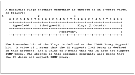
An EVPN device that is enabled with IGMP-snooping and supports BGP SMET Route Type-6 will add a BGP Extended community called EVPN Multicast Flags (EVPN-MF) to its EVPN Type-3 route.
In addition, this device will set the least significant bit (LSB) of the octet in the community to 1 to suggest support for SMET capability. A device that supports IGMP-snooping and supports BGP SMET Route Type-6 capability must add the EVPN-MF community and set the LSB in the octet to 1.
Also, if a device is not IGMP-snooping enabled _or_ does not support BGP SMET Route Type-6 _or if it wants traffic flooded to it irrespective of listeners, it will either skip adding the EVPN-MF community or add the EVPN-MF community but reset the LSB of the octet in the community to 0 to suggest traffic be flooded to this PE.
Once this community is exchanged in EVPN Type-3 route, the participating PEs have information on which LEAF devices have to be included for all traffic, and to which LEAFs have to be selectively forwarded.
Additional Procedures for Selective Multicast Forwarding
Forward L2-switched Traffic to L3-PIM Spines
When a LEAF receives traffic from its access interface for group G1, the LEAF should forward traffic selectively only to those EVPN PE devices that have originated a Type-6 for that group G1.
In addition to forwarding traffic to the LEAF devices that have originated Type-6 for group G1, the Ingress should forward the traffic to the L3-PIM devices, too. If there are no remote listeners for the group, the traffic must still be sent to the L3-PIM devices alone.
The rationale for this is as follows. A L3-PIM device performs Inter-subnet routing from the source-VLAN onto other receiver VLANs (Inter-VLAN Multicast will be illustrated in detail in EVPN Intra-Multicast Optimization with Multihoming chapter). So, the L3-PIM device should attract and receive the traffic on the source-VLAN all the time. Also, the L3-PIM device that is PIM DR should register the multicast source to the PIM-RP. So the traffic should reach the L3-PIM device all the time (see Figure 9).
How Is a L3-PIM Device Detected?
In the last section, the Ingress forwards the traffic for group G1 to L3-PIM devices. This L3-PIM device is detected by virtue of the L3-PIM device resetting the LSB in EVPN-MF community in a BGP Type-3 route.
It is a bit of a paradox that the L3-PIM device is enabled with IGMP-snooping, capable of originating SMET Type-6 routes as well as capable of Selective (SMET) Forwarding. However, the L3-PIM device has to attract traffic for the purposes of Inter-VLAN routing and registering the multicast source with the RP.
Towards this end, the L3-PIM either skips adding the EVPN-MF community or adds the EVPN-MF community but resets the LSB in the octet to 0. Any LEAF Ingress PE that receives such a Type-3 will flood all the traffic to this L3-PIM device.
Accommodating Devices That Do Not Support Snooping/SMET Route
In certain deployments, there may be few LEAF devices that are not enabled with IGMP-snooping. Also, there may some EVPN LEAF devices that are enabled with IGMP-snooping, but the devices do not have the support for originating BGP Type-6 route.
Such legacy LEAF devices do not convey remote listener interest multicast interest to other PEs. Let’s suppose that LEAF-5 in Figure 10 is a legacy device that does not support IGMP-snooping.
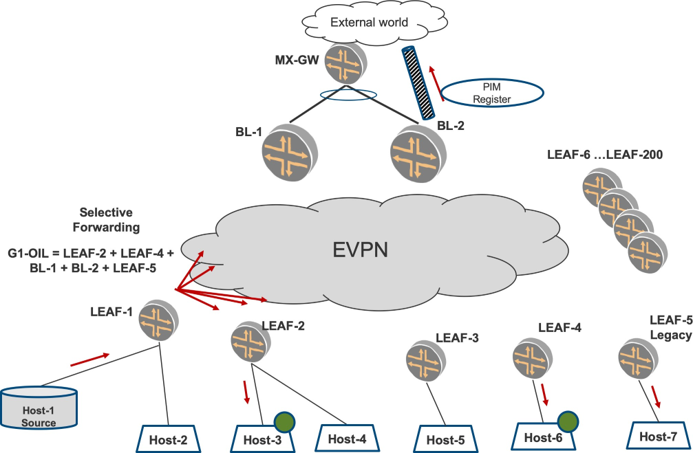
However, such legacy LEAF devices may have listeners interested in traffic for the group G1. Since they do not originate a Type-6 route, the Ingress does not have a way to determine if there are listeners behind such legacy PEs or not. If the Ingress does not forward the traffic to the legacy PEs, the listeners behind the legacy PEs will not get the traffic. So the Ingress has to flood the traffic to the legacy PEs and in this way ensure compatibility with devices that do not support optimized multicast procedures.
How is a Legacy Device Detected?
In an earlier section, we saw that the Ingress forwards the traffic for group G1 to legacy LEAF devices. This legacy LEAF is detected by virtue of an absence of an EVPN-MF community in a BGP Type-3 route.
The Ingress device, when it learns of the LEAF devices from Type-3, will check for this community. If Ingress detects that the EVPN-MF is not present, the Ingress will deduce that it is a legacy device. Based on this, the Ingress will always flood the traffic to this legacy device.
In the Figure 10, for G1, LEAF-1 will have in its OIL, LEAF-2, LEAF-4, the BLs, and LEAF-5. Other LEAFs that don’t have listeners behind them will not be part of the OIL.
Forwarding Prefix for L3-PIM and Legacy Devices to Flood Traffic
To achieve flooding of traffic in the special cases described earlier, where the egress PEs want to attract traffic for_all groups, a default multicast prefix route of 224/4 is installed with its OIL containing L3-PIM and legacy devices. This will cause traffic for flows that don’t have a specific route entry installed (for example, 235.1.1.1) to hit this prefix 224/4 and reach the L3-PIM devices. If there were listeners existing for group 235.1.1.1, the OIL for 235.1.1.1 will include the L3-PIM and legacy devices.
Flood 224/24 Groups (for example, OSPF/LDP Hellos) Everywhere
Consider special well-known multicast groups like 224.0.0.5, 224.0.0.13. These are well-known multicast groups for different purposes, for example, 224.0.0.5 is a multicast group used for OSPF Hellos, 224.0.0.13 for PIM Hellos. Such well known groups are specified to be in the range of 224.0.0.0/24 (224.0.0.1 to 224.0.0.255).
The traffic that is destined for such groups should be flooded everywhere because LEAF devices do not originate Type-6 for such groups. For example, there may be L3-OSPF devices behind LEAF-1 and LEAF- 2. The OSPF devices have to discover each other using hellos. These hello messages have to be forwarded to each other by the LEAFs. So, the Ingress PE installs a 224.0.0.0/24 specific forwarding entry that has in its next hop all the PEs in the fabric. This happens without any need for configuration.
Flood User-configured Groups Everywhere
There may be scenarios where the operator may want some multicast groups to be flooded everywhere ir respective of the presence of listeners. These groups may not fall in the 224/24 range. Suppose there is a group 230.1.1.1 for which the operator desires the traffic to be flooded everywhere. This can be accomplished by having a configuration on the Ingress. The configuration will contain a list of groups for which the traffic should be flooded. When traffic does arrive for 230.1.1.1, irrespective of listeners on access or over the core, the traffic is flooded everywhere.
Rules for Selective Multicast Forwarding
So the rules of Selective Multicast Forwarding for traffic destined for group G1 are enhanced in the following manner:
L2-forwards the multicast traffic for group G1 towards those EVPN PEs that have originated a BGP Type-6 SMET route for that group G1.
L2-forwards the multicast traffic for group G1 towards L3-spine devices for the purpose of Inter-subnet multicast and registering the multicast source with PIM-RP.
L2-forwards the multicast traffic for group G1 towards the legacy LEAF devices that are not enabled with IGMP snooping or those that do not support BGP Type-6 SMET Route origination.
L2-forwards the multicast traffic for group in range 224.0.0/24, to all EVPN PEs in the fabric.
L2-forwards the multicast traffic for user-configured groups to all EVPN PEs in the fabric.
Chapter Summary
This chapter explored optimized multicast with IGMP-snooping and Selective (SMET) Forwarding. In large scale multicast deployments with a high volume of traffic, these optimizations play a key role in conserving bandwidth in both core and access, and also in the replication and packet processing load on the participating EVPN devices.
It also explored different signaling procedures with SMET Type-6 routes and how interoperability is achieved with legacy devices. We explored the different outliers that an EVPN device takes into consideration when building the list of PEs, therefore, L3-PIM devices, legacy devices, etc., and also the special forwarding rules needed for link local multicast addresses 224/4.
SMET Forwarding is enabled when IGMP-snooping is enabled. It may be the case that some groups need to be flooded everywhere. This can be achieved by a configuration where the operator can cherry-pick the group addresses where traffic needs to be flooded.
In EVPN Intra-Multicast Optimization with Multihoming chapter we will explore optimized multicast forwarding in multihomedscenarios..
Configuration
The reference topology is shown in Figure 11.
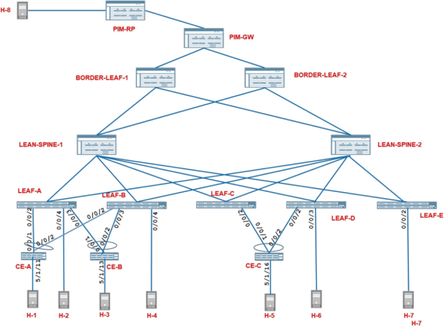
Having reviewed intra-VLAN multicast traffic optimization for EVPN, let’s now see it in action by enabling IGMP-snooping and Selective (SMET) Forwarding and observing how traffic forwarding is optimized.
Configure IGMP-Snooping
Turn on IGMP-snooping on the EVPN PEs. Upon enabling IGMP-snooping on a BD/VLAN level, SMET Type-6 route origination Selective (SMET) Forwarding is enabled, too.
Configure VLAN-101 on LEAF-5. However, since we want LEAF-5 to simulate a legacy device that does not support IGMP snooping, we do not turn on IGMP-snooping on any of the VLANs on LEAF-5.
Before we begin, stop the traffic, and the receivers on RT, and load the following configuration snippets on the following devices:
LEAF-1, LEAF-2, LEAF-3, LEAF-4:
BL-1, BL-2:
Configure VLAN-101 on LEAF-5
Load this configuration snippets on LEAF-5:
Traffic Verification
From Host-1, start sending multicast traffic at 10 pps for group 225.1.1.1 in VLAN-101.
On Host-6 that is single-homed to LEAF-4, start a receiver for the multicast group, 225.1.1.1 on VLAN-101.
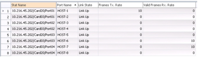
Traffic Statistics on Router Tester
From the RT statistics in Figure 12, you can see that the traffic sent by Host-1 at 10 pps is now being received only by the interested receiver, Host-6, and the legacy device, Host-7, in VLAN-101.
Multicast Traffic Outputs - LEAF-1
As it did previously, the load balanced multicast traffic arrives on the access interface ae0 on LEAF-1. However, the multicast traffic arriving on LEAF-1 is no longer forwarded on any of the access interfaces on LEAF-1, since there are no receivers, thus avoiding waste of access side bandwidth:
lab@LEAF-1> monitor interface traffic detail
Interface Link Input packets (pps) Output packets (pps) Description
…
xe-0/0/4   Up       0         (0)      2564        (0)    TO Host-2
…
ae0        Up     9467        (10)       0         (0)      TO CE-1
ae1        Up       0         (0)      2560        (0)      TO CE-2
…
The multicast traffic is forwarded on the VTEPs towards Border-LEAF PEs (101.101.101.101 and 102.102.102.102) and LEAF-5 (109.109.109.109).
The traffic is also sent on the VTEP towards LEAF-4 (108.108.108.108) that has an interested receiver.
LEAF-2 (106.106.106.106) and LEAF-3 (107.107.107.107) that do not have any interested receivers are spared of the traffic:
lab@LEAF-1> show interfaces vtep extensive | grep “VXLAN Endpoint Type: Remote|Output packets.*pps”
    VXLAN Endpoint Type: Remote, VXLAN Endpoint Address: 106.106.106.106…
     Output packets:                 4713                    0 pps
    VXLAN Endpoint Type: Remote, VXLAN Endpoint Address: 101.101.101.101…
     Output packets:                 9375                   10 pps
    VXLAN Endpoint Type: Remote, VXLAN Endpoint Address: 108.108.108.108…
     Output packets:                 5653                   10 pps
    VXLAN Endpoint Type: Remote, VXLAN Endpoint Address: 107.107.107.107…
     Output packets:                 4713                    0 pps
    VXLAN Endpoint Type: Remote, VXLAN Endpoint Address: 109.109.109.109…
     Output packets:                 4664                    9 pps
    VXLAN Endpoint Type: Remote, VXLAN Endpoint Address: 102.102.102.102…
     Output packets:                 9375                    9 pps
Multicast Traffic Outputs - LEAF-4
The access side IGMP-snooping functionality ensures that the multicast traffic arriving on LEAF-4 is forwarded on the single-homed interface, xe-0/0/3.0, that now has a receiver, but it is not forwarded on the multihomed interface ae0.0 that does not have a receiver:
lab@LEAF-4> monitor interface traffic detail
Interface    Link Input packets (pps) Output packets (pps) Description
…
xe-0/0/3      Up       0         (0)      5660        (10)   TO Host-6
ae0           Up      505        (0)      2481         (0)     TO CE-3
…
Multicast Traffic Outputs - LEAF-5
LEAF-5 being a legacy device and being configured with VLAN-101, now receives the traffic and floods it on its access interface, xe-0/0/2.0, though it does not have a receiver:
lab@LEAF-5> monitor interface traffic detail
Interface    Link  Input packets (pps) Output packets (pps) Description
…
xe-0/0/2      Up        0         (0)      4666        (10)   TO Host-7
…
Multicast Traffic Outputs – BL-1 and BL-2
Again, we will ignore the traffic forwarding behavior on these devices until we get to EVPN Intra-VLAN Multicast Without Optimization chapter.
Detailed Control Plane Verification
Verification of Base EVPN IGMP Snooping State
Verify that IGMP-snooping has been enabled on VLAN-101 on all the EVPN PEs, except LEAF-5:
lab@LEAF-1> show evpn instance extensive
Instance: default-switch
…
  Number of bridge domains: 2
    VLAN   Domain ID  … IPv4 SG sync IPv4 IM core nexthop …
    101    101        … Enabled             131082 …
    102    102        … Enabled             131084 …
Similar outputs can be seen on LEAF-2, LEAF-3, LEAF-4, BL-1, and BL-2.
Now let’s verify that the Type-3 route being advertised by the IGMP-snooping enabled regular LEAF EVPN PEs (LEAF-1 through LEAF-4) now carries the Multicast Flags extended community with the “IGMP Proxy Support” bit set:
lab@LEAF-1> show route extensive table default-switch.evpn.0 evpn-ethernet-tag-id 101 matchprefix
3:* protocol bgp| grep “entry|Communities”
…
3:106.106.106.106:1::101::106.106.106.106/248 IM (1 entry, 1 announced)
            Communities: target:1:1 encapsulation:vxlan(0x8) evpn-mcast-flags:0x1:snoopingenabled
3:107.107.107.107:1::101::107.107.107.107/248 IM (1 entry, 1 announced)
            Communities: target:1:1 encapsulation:vxlan(0x8) evpn-mcast-flags:0x1:snoopingenabled
3:108.108.108.108:1::101::108.108.108.108/248 IM (1 entry, 1 announced)
            Communities: target:1:1 encapsulation:vxlan(0x8) evpn-mcast-flags:0x1:snoopingenabled
Verify that the non-IGMP-snooping enabled LEAF-5 continues to advertise Type-3 routes without the Multicast Flags Extended community or with the “IGMP Proxy Support” bit reset in the Multicast Flags extended community:
lab@LEAF-1> show route extensive table default-switch.evpn.0 evpn-ethernet-tag-id 101 matchprefix
3:109* protocol bgp| grep “entry|Communities”
3:109.109.109.109:1::102::109.109.109.109/248 IM (1 entry, 1 announced)
                Communities: target:1:1 encapsulation:vxlan(0x8)
Verify that border LEAF EVPN PEs (BL-1 and BL-2) that are enabled with IGMP-snooping and L3-multicast (PIM), advertise Type-3 routes without the Multicast Flags Extended community or with the “IGMP Proxy Support” bit reset in the Multicast Flags extended community:
lab@LEAF-1> show route extensive table default-switch.evpn.0 evpn-ethernet-tag-id 101 matchprefix
3:* protocol bgp| grep “entry|Communities”
3:101.101.101.101:1::101::101.101.101.101/248 IM (1 entry, 1 announced)
                Communities: target:1:1 encapsulation:vxlan(0x8)
3:102.102.102.102:1::101::102.102.102.102/248 IM (1 entry, 1 announced)
                Communities: target:1:1 encapsulation:vxlan(0x8)
Verify that the snooping-enabled LEAF PEs have programmed their multicast forwarding table such that all unknown multicast ingress traffic is forwarded towards the border LEAF PEs and towards the non- IGMP-snooping enabled PEs:
lab@LEAF-1> show multicast snooping route extensive VLAN VLAN-101
…
Group: 224.0.0.0/4
    Source: *
    VLAN: VLAN-101
    Mesh-group: __all_ces__
        Downstream interface list:
        evpn-core-nh -(131082)
…
lab@LEAF-1> show evpn multicast-snooping next-hops 131082 detail
…
ID           Refcount KRefcount Downstream interface Addr
131082           3        1     vtep.32770-(1756)
                                vtep.32773-(1764)
                                vtep.32774-(1765)
Verification of EVPN IGMP Proxy State with Remote Receivers
Verify that on LEAF-4, the IGMP group membership has been learned on the VLAN-101 interface xe-0/0/3.0 by snooping the IGMP reports:
lab@LEAF-4> show igmp snooping membership VLAN VLAN-101 225.1.1.1
Instance: default-switch
VLAN: VLAN-101
…
Interface: xe-0/0/3.0, Groups: 1
    Group: 225.1.1.1
        Group mode: Exclude
        Source: 0.0.0.0
Last reported by: 18.18.18.70
Group timeout: 209 Type: Dynamic
Verify that LEAF-4, having learned local IGMP membership for the group 225.1.1.1, builds local EVPN IGMP-proxy state and originates Type 6 IGMP proxy routes to notify remote PEs of its interest in receiving multicast traffic for the group:
lab@LEAF-4> show igmp snooping evpn proxy VLAN VLAN-101 225.1.1.1
Instance: default-switch
  Bridge-Domain: VLAN-101, VN Identifier: 101
        Group       Source   Local    Remote
        225.1.1.1   0.0.0.0    1           0
lab@LEAF-4> show evpn igmp-snooping proxy l2-domain-id 101 group 225.1.1.1 extensive
Instance: default-switch
  VN Identifier: 101
        Group       Source   Local Remote Corenh Flood
        225.1.1.1   0.0.0.0    1      0      0       0
lab@LEAF-4> show route table default-switch.evpn.0 evpn-ethernet-tag-id 101 matchprefix
6:* extensive protocol evpn
default-switch.evpn.0: 83 destinations, 83 routes (83 active, 0 holddown, 0 hidden)
6:108.108.108.108:1::101::225.1.1.1::108.108.108.108/520 (1 entry, 1 announced)
        *EVPN Preference: 170
…
              Protocol next hop: 108.108.108.108
…
              Communities: encapsulation:vxlan(0x8)
              IGMP flags: 0xa
Verify that all remote PEs process this EVPN Type-6 and learn that LEAF-4 is an interested remote EVPN receiver for the group:
lab@LEAF-1> show route table default-switch.evpn.0 evpn-ethernet-tag-id 101 matchprefix
6:* extensive
default-switch.evpn.0: 82 destinations, 82 routes (82 active, 0 holddown, 0 hidden)
6:108.108.108.108:1::101::225.1.1.1::108.108.108.108/520 (1 entry, 1 announced)
        *BGP Preference: 170/-101
             Route Distinguisher: 108.108.108.108:1
…
             Source: 108.108.108.108
             Protocol next hop: 108.108.108.108
…
             Communities: target:1:1 encapsulation:vxlan(0x8)
             Import Accepted
             IGMP flags: 0xa
…
lab@LEAF-1> show evpn igmp-snooping proxy l2-domain-id 101 group 225.1.1.1 extensive
Instance: default-switch
  VN Identifier: 101
     Group      Source   Local Remote Corenh Flood
     225.1.1.1  0.0.0.0    0     1    131087     0
lab@LEAF-1> show igmp snooping evpn proxy VLAN VLAN-101 225.1.1.1
Instance: default-switch
  Bridge-Domain: VLAN-101, VN Identifier: 101
     Group      Source   Local Remote
     225.1.1.1  0.0.0.0    0        1
Verification of Multicast Forwarding State with Remote Receiver
Verify that the multicast forwarding state created for group 225.1.1.1 in LEAF-4 includes the interested single-homed interface xe-0/0/3.0:
lab@LEAF-4> show multicast snooping route extensive VLAN VLAN-101 group 225.1.1.1
…
Group: 225.1.1.1/32
    Source: *
    VLAN: VLAN-101
    Mesh-group: __all_ces__
        Downstream interface list:
        evpn-core-nh -(131082) xe-0/0/3.0 -(1730)
…
Verify that on all other PEs, LEAF-4 (vtep.32771) has been added to the EVPN core next hop for group 225.1.1.1. Note that in addition BL-1 (vtep.32770), BL-2 (vtep.32774), and LEAF-5 (vtep.32773) will also be present in the EVPN core next hop for the group:
lab@LEAF-1> show evpn igmp-snooping proxy l2-domain-id 101 group 225.1.1.1 extensive
Instance: default-switch
  VN Identifier: 101
   Group     Source   Local Remote Corenh Flood
   225.1.1.1 0.0.0.0  0     1      131087     0
lab@LEAF-1> show evpn multicast-snooping next-hops 131087 detail
…
ID    Refcount KRefcount Downstream interface Addr
131087    3         1    vtep.32770-(1756)
                         vtep.32771-(1761)
                         vtep.32773-(1764)
                         vtep.32774-(1765)
Verify that the multicast forwarding state created for group 225.1.1.1 includes the EVPN core next hop shown above:
lab@LEAF-1> show multicast snooping route extensive VLAN VLAN-101 group 225.1.1.1
…
Group: 225.1.1.1/32
    Source: *
    VLAN: VLAN-101
    Mesh-group: __all_ces__
        Downstream interface list:
        evpn-core-nh -(131087)
…