ON THIS PAGE
Assisted Replication
In EVPN Intra-VLAN Multicast Without Optimization chapter we explored the different procedures for multicast data forwarding like ingress replication, DF/NDF forwarding, and local bias rules.
Typically, data centers have several top-of-rack (TOR/LEAF) switches (in the order of hundreds) that have less port density, have less forwarding/processing capability, and are less expensive. The QFX5110, for instance, is such a device, and is the right fit for a LEAF role.
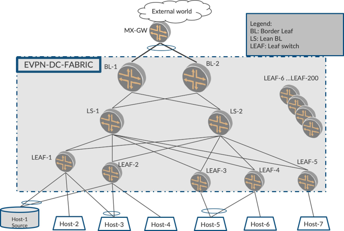
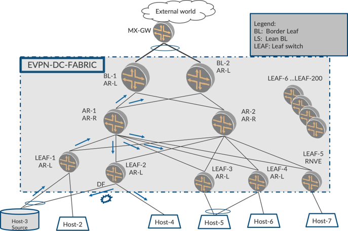
Also, a data center physical topology looks similar to Figure 1 and has the following components:
LEAF Layer: There are several LEAFs, (QFX 5110s) that connect to the VM Hosts, bare-metal servers (BMS), etc.
Border LEAF: There are couple of LEAF devices called Border-LEAF (BL) devices (QFX10K) that are used to connect the DC fabric to the outside world over a gateway (MX-GW).
Lean Spine: There are couple of lean spine devices (LS) (QFX10K) that are used to physically interconnect the participating EVPN devices. These lean spine devices serve as physical interconnects only, do not host any access interfaces, and generally do not participate in an EVPN overlay. They are part of the BGP underlay.
Ingress Replication Characteristics and Challenges
When multicast source sends traffic for different flows, say, for IPTV applications, the traffic rate is typically very high (in order of 4Mbps per flow, for example, HD streams). When such a high rate of traffic arrives on LEAF-1, LEAF-1 shall Ingress replicate the traffic to all other PEs in the fabric. To achieve this, for each packet LEAF-1 receives on the access interface, it replicates one copy per remote PE and sends it over the EVPN core as shown in Figure 2.
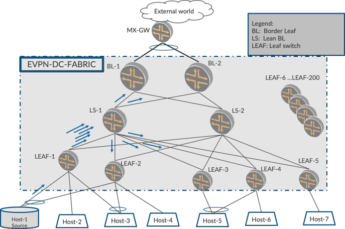
With, say, 1000 flows at 4 Mbps per flow, and about 200 PEs in the Fabric, LEAF-1 sends out (1000 * 200 * 4 Mbps = 800Gbps). Two situations arise here.
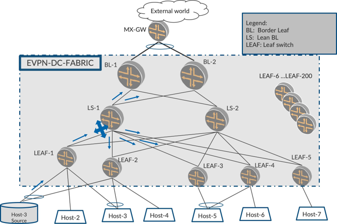
Since LEAF-1 is a device with less capacity, it is burdened to make 200 copies (one per PE) of the incom-ing heavy traffic flow. This can potentially melt the Ingress.
Though the overlay traffic is 800 Gbps distributed to 200 PEs, (4 Gbps per PE in the logical topology), LEAF-1 sends all the 800 Gbps traffic on the physical link between LEAF-1 and LS-1. Thereafter, LS-1, forwards these packets to each of the other PEs at 4 Gbps each. The link between LS-1 to LEAF-3, let’s say, carries 4Gbps, which is expected and is not a problem. However, the link between LEAF-1 and LS-1 is severely overutilized leaving no space for other applications and potential traffic drops.
We have just illustrated this situation with one multicast source. If there are several sources behind other LEAFs sending traffic at high rates, many LEAFs will be effected as the links that go from the LEAF to the LS will also choke
Assisted Replication
Using the above scenario, let’s explore if there is anything that can be done to mitigate the problems of (i) the inability of LEAF-1 to replicate to several PEs, with the traffic coming in at high rate, and (ii) the over utilization of the link between LEAF-1 and LS-1, since that link has to carry the packets destined to all PEs in the underlay.
Wouldn’t it be nice if LS-1, which typically is a high-end device, could ‘assist’ in the responsibility of replication to other PEs? Yes. If LS-1 can assist LEAF-1 with the load of replication to other PEs, both the above problems are addressed. How?
Let’s say LEAF-1 sends only one copy of the packet to LS-1, and LS-1 takes over the role of replication and replicates to other EVPN devices in the fabric. The LEAF-1 needs to send only one packet to the LS-1, so the replication load on LEAF-1 and the number of packets that flow over the link between LEAF-1 and LS-1 is reduced by a factor of 200.
Of course, LS-1 should have the capability and configuration to ‘assist’ such replication. Also, LS-1 should exchange this capability with other EVPN devices and the other devices to offload the responsibility of replication to LS-1. Which tunnels the traffic should be forwarded onto will also be coordinated.
Enter assisted replication. In this chapter, we describe assisted replication (AR), its characteristics, and the benefits it brings to the table in reducing load and complexity. In later chapters, once we have introduced optimized multicast, we shall also explore how AR, in conjunction with optimized multicast, effectively makes the DC Fabric operate in a slick manner for multicast traffic.
An Important Thing to Note
AR functionality is optional. That it is to say, it is not mandatory to deploy AR to be able to optimize multi-cast traffic (a discussion of which is coming in later chapters). Some customers ensure multicast traffic is first optimized in the fabric, and then proceed with addressing the problems of load and link bandwidth utilization. However, for academic reasons, AR fits in well in this chapter in terms of a staged understanding of the different mechanisms of EVPN multicast.
Building Blocks of Assisted Replication
There are three components of the AR solution in the fabric as shown in Figure 4:
the role of AR-LEAF
the role of AR-Replicator
the role of RNVE (Regular Network Virtualization Equipment): a device that does not support the AR feature
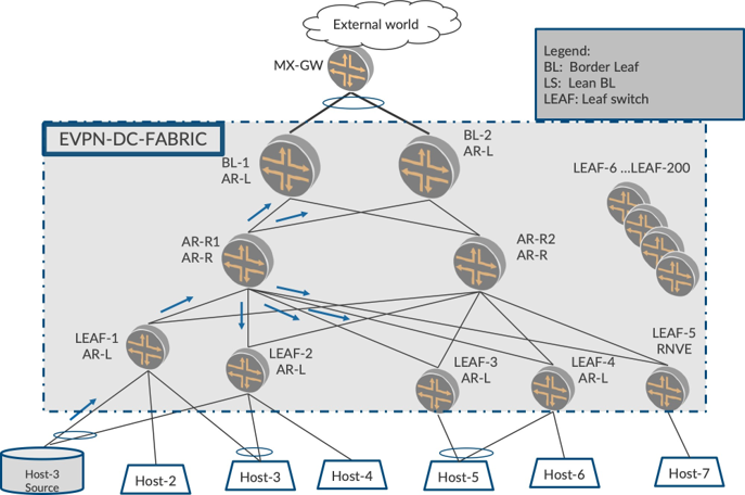
The AR-LEAF in our topology will be LEAFs, and the AR Replicator role will be LS-1 and LS-2. LS-1 and LS-2, prior to AR, participate in the underlay build-up of the fabric. With AR, these devices will perform the additional roles of AR replicator in the overlay, too. This way, there is no additional introduction of hardware and the existing device is utilized to solve the two hard problems of Ingress Replication described earlier.
LEAF-1, LEAF-2, LEAF-3, and LEAF-4 are configured as AR-LEAF. (AR-L)
BL-1 and BL-2 are configured as AR-LEAF, too.
AR-R1 and AR-R2 are configured as the AR-Replicators.
(AR-R) There is no AR configuration on LEAF-5. So this makes LEAF-5, the RNVE.
Requirements of Assisted Replication In Fabric
The EVPN PEs should be designated with a specific AR role using a configuration (AR-LEAF/Replicator) or lack thereof. (RNVE)
The EVPN devices should be able to detect the presence of other AR devices and their roles.
The AR-capable devices (therefore, AR-LEAFs and AR-Replicators) should accommodate RNVE devices (therefore, AR-incapable devices).
The AR-LEAF PEs should be able to build AR-tunnels to AR-replicators to send multicast traffic to AR-Replicators.
The AR-Replicator PEs should be able to use existing IR-tunnels to send replicated multicast traffic to other AR-LEAF devices and RNVEs.
The AR-LEAF and AR-Replicators should be able to use the existing IR-tunnels to receive traffic from RNVEs.
Ensure EVPN multihoming behavior and forwarding are at parity with IR.
There should be provisions to support multiple AR-Replicator roles for load balancing of the replication. The AR-LEAF devices should be able to load-balance amongst the multiple AR-Replicator devices. In typical customer deployments, there would be two or four AR-Replicators in the Fabric for load balancing and resiliency.
Tunnel Building For Assisted Replication In Fabric
AR-R1 and AR-R2, by virtue of being replicators, advertise an AR Type-3 route in addition to the usual IR Type-3 of today. The AR Type-3 route parameters are used in building the AR-tunnels from the AR-LEAF to the AR-Replicator.
LEAFs 1-4, the AR-LEAFs, on receiving the AR-Type-3 route from AR-R1 and AR-R2, deduce the presence of replicators and build the AR-tunnel to the replicators.
The AR-LEAF detects multiple replicators, by virtue of how they build the load balancing capability in their AR-tunnels. Therefore, some flows will be sent to AR-R1 for replication, others to AR-R2.
AR-LEAF and AR-Replicators and the RNVE build the IR-tunnels with each other based on existing Type 3 routes.
The AR-LEAF and AR-Replicators keep their IR-tunnels to each other for two reasons: (1) for a LEAF to receive replicated traffic from AR-R, and, (2) to fall back to IR when the AR-tunnel fails for any reason
Assisted Replication Traffic Forwarding Rules
Assisted Replication Traffic Forwarding with Traffic Arriving From Behind AR-LEAF
When multicast traffic for a flow arrives on the access interface on LEAF-1, LEAF-1 sends the traffic to one of the replicators, such as AR-R1. LEAF-1 sends only one copy of this traffic to AR-R1 on the AR-tunnel.
AR-R1, upon receiving the traffic on the AR-tunnel, replicates this packet to the other AR-LEAFs, other ARs and RNVEs, (LEAF-2, LEAF-3, LEAF-4, BL-1, BL-2), (AR-2), and (LEAF-5). The replicated traffic is sent to the AR-LEAFs and the RNVEs on the IR tunnel.
The receiving PEs get this replicated traffic in their existing IR tunnel. Hence, the behavior is same as with existing IR tunnels. Therefore, they receive the multicast traffic on the IR tunnel and forward it to access interfaces.
Assisted Replication Traffic Forwarding with Traffic Arriving From Behind RNVE
When multicast traffic arrives on the access interface of RNVE (LEAF-5), the RNVE itself replicates and sends one copy each of the traffic to all the other LEAFs, ARs, and BLs (classic Ingress Replication) on the IR tunnel. Remember, there is no AR-configuration or AR-tunnel on RNVE.
The AR replicators, upon receiving this traffic from RNVE, should not replicate further to ensure duplicates do not occur. How is the AR replicator able to distinguish which traffic to replicate (from behind the AR-LEAF) and which traffic not to replicate (from behind RNVE)? AR-1 figures this out by checking on the tunnel type on which the traffic arrived. Therefore, if traffic arrived on the AR-tunnel, it replicates to other PEs, and if it arrives on the IR-tunnel, it does not replicate.
Cardinal AR/IR Tunnel Forwarding Rules Summary
AR-Replicator
On AR-R, if traffic arrived on AR-tunnel, replicate:
send replicated traffic to LEAF, RNVE, and AR on IR-tunnel
On AR-R, if traffic arrived on IR-tunnel, do not replicate.
AR-LEAF
On LEAF-1, for access traffic, send one copy to AR-R on AR-tunnel
On LEAF-1, traffic arriving on IR, forward on access (existing behavior).
RNVE: Existing IR Forwarding and Receiving Rules apply
Assisted Replication In a Multihoming Environment
EVPN Multihoming Local Bias Refresher
Please revisit EVPN Intra-VLAN Multicast Without Optimization chapter’s coverage of EVPN multicast forwarding in multihomed topologies. Here’s a quick version: let’s say that in Figure 5, LEAF-1 and LEAF-2 are multihomed on ESI-1, and that multicast traffic is arriving on ESI-1 on LEAF-1. When LEAF-1 Ingress replicates the packet to its multihomed peer LEAF-2, LEAF-2 should not forward on ESI-1 as duplicates/loops would occur. How does LEAF-2 avoid forwarding on ESI-1?
LEAF-2 looks at the source-IP of the packet and figures out that it has originated from LEAF-1. Based on this, LEAF-2 does not forward on the ESIs that are multihomed with LEAF-1. In this case, ESI-1. LEAF-2 would forward on other single-homed interfaces and on other ESIs where it is not multihomed with LEAF-1.
Assisted Replication In a Multihomed Environment – AR-R Should Retain the Src-IP of the Replicated Packet
Given the above, when we introduce AR in the fabric, we need to be careful with the packet that the AR replicates and sends. That is to say, it is paramount that the source-IP of the replicated packet is retained as LEAF-1 for local bias to work correctly.
If the AR-R sets its own IP (AR-R-IP) as the Src-IP of the replicated packet, LEAF-2 would end up sending on ESI-1 (since LEAF-2 thinks it is a packet from AR-R (core) and not from LEAF-1).
If this occurs, the LEAF-2 is in a spot because it cannot really tell if this replicated packet originated from LEAF-1 (multihomed) or from LEAF-3 (not multihomed). LEAF-2 will treat it as regular BUM packet coming in from the core and forward it to the ESI (since it is DF on the ESI) causing duplicates/loops on the MH-ESI.
It may not always be possible for the AR-Replicator to retain the Src-IP of the incoming packet onto the replicated packet (on some platforms).
Assisted replication functionality on AR-R is about receiving a packet on one VTEP (AR-tunnel) and then replicating it on other VTEPs in (IR-tunnel). When the AR device replicates and sends out the packet on VTEP following classic forwarding procedures, on some platforms the AR device can place only its own IP, (AR-R-IP) as the Src-IP.
Typically, when a PE Ingress replicates traffic arriving on access, it builds multiple copies and sends to the remote PEs with the Src-IP of the outer VXLAN header as its own IP. Prior to AR, there was never a need for transforming a packet arriving on core and sending back to the core with the retained Src-IP.
Overall, Ingress replication was always about taking an incoming packet from access interface and replicating it towards the core stamping its own Src-IP in the outer header. It may have been hard to add addi- tional functionality to be able to take an incoming packet from the core interface and replicate it towards the core interface itself while also stamping the Src-IP as the incoming packet’s Src-IP.
Since special handling is involved and this is unique forwarding behavior, some platforms do not have the capacity to retain the Src-IP of LEAF-1.
Enhanced Assisted Replication Procedure to the Rescue
AR provides a huge benefit in that the limitation of some platforms described in the above section as not able to retain the Src-IP should not preclude adoption of AR. If it was somehow possible for the LEAF/ Replicator devices to cooperate and handle this situation, it would be worthwhile. Fortunately, this can be solved, and it is referred to as Enhanced Assisted Replication.
Capability Exchange
In its Type-3 AR route the AR-Replicator advertises its ability to retain the Src-IP by way of an extended community value. A value of Base-AR mode in the community would mean, ‘I can retain the Src-IP of LEAF-1’ and a value of ‘Enhanced-AR’ mode in the community would mean, ‘I am not capable of retaining the Src-IP of LEAF-1.’
AR-R Capable of Retaining the Source-IP of LEAF-1
If AR-R is capable of retaining Src-IP, then all is well. The AR-R appropriately sends the community value suggesting that it is in Base AR mode. Based on the exchange, the AR-LEAF devices and AR-Replicatordevices follow the procedures described earlier in the plain vanilla AR procedures.We are good in multihomed scenarios, too.
Since the Source-IP of LEAF-1 is retained in the replicated packet, LEAF-2, upon receiving packet from the ARR, figures out the Src-IP of the packet to be that of LEAF-1. With this, it performs local-bias and skips forwarding on the ESI.
AR-R Not Capable of Retaining the Source-IP of LEAF-1
If AR-R is not capable of retaining Src-IP, then the AR-R sets the community value suggesting that it is in Enhanced-AR-mode. The AR-LEAF devices on hearing this community get into Enhanced-AR-mode. In this case of enhanced-AR mode, extra procedures are required of both AR-R and AR-L as shown in Figure 6.
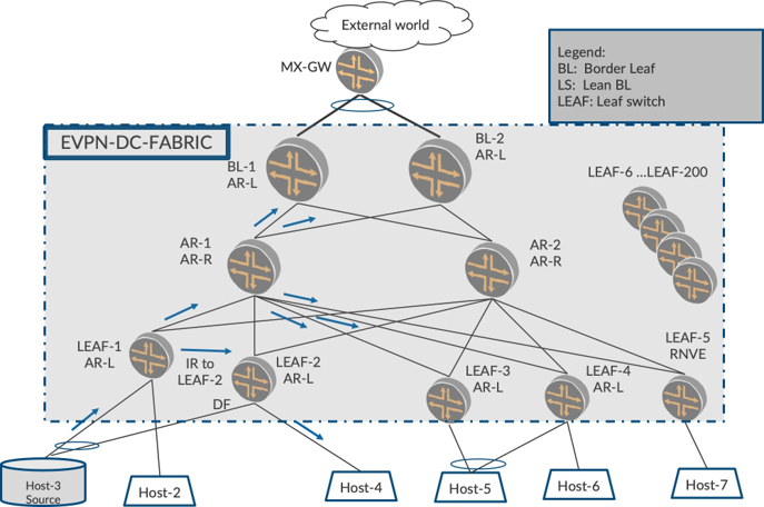
In Figure 6, AR-R deduces which AR-LEAF PEs are multihomed on a VLAN. This information is avail- able and can be deduced from the Type 1 route per EVI that is advertised for ESIs. MAC-aliasing uses this information already.
Once AR-R deduces LEAF-1 and LEAF-2 are multihomed, when it receives traffic from LEAF-1 and replicates to other LEAFs, AR-R skips send the replicated packet to LEAF-2 alone, therefore, the multihomed peers that LEAF-1 is multihomed to.
Since AR-R has skipped sending to LEAF-2, there should be some other means of sending that traffic to LEAF-2. So LEAF-1, the AR-LEAF, sends one copy of the access traffic to the replicator and one another copy to LEAF-2 alone over IR-tunnel. (to its MH peers on that VLAN). This needs to be sent to LEAF-2 because LEAF-2 may have other single-homed interfaces where this traffic needs to be sent.
When LEAF-2 receives traffic from LEAF-1 it will look at the Src-IP of the packet and will do what’s needed (DST-LOCAL-BIAS) . Since LEAF-2 has already directly received from LEAF-1, it can perform the local-bias and not send on the ESI link but can forward on the single-homed interfaces.
This way we have arrived at the middle ground of deriving the benefits of AR as it is also handled in multi-homing scenarios.
Overall Assisted Replication Procedures
AR-Replicator:
On AR-R, if traffic arrived on AR-tunnel, replicate
Send replicated traffic to LEAF, RNVE, and AR on IR-tunnel
On AR-R, if traffic arrived on IR-tunnel, do not replicate
AR-LEAF:
On LEAF-1, for access traffic, send one copy to AR-1 on AR-tunnel
LEAF-1, traffic arriving on IR, forward on access (existing behavior)
RNVE: Existing IR Forwarding and Receiving Rules apply
Enhanced-AR Additional Forwarding Rules, in Addition to Base-AR mode:
AR-R skips sending the replicated packet to LEAF-2.
LEAF-1 makes an extra copy to LEAF-2 alone, and sends over IR-tunnel.
Chapter Summary
This chapter explored assisted replication, its benefits, basic procedures, platform limitations with EVPN MH scenarios, and procedures to detect and accommodate it.
With AR we transferred the load of replication from low-end LEAF devices to capable highend replicator devices effectively reducing replication load on LEAF and avoiding the overuse of the link bandwidth between the LEAFs and the Lean Spine. The existing underlay Lean Spine performs the additional role of Replicator.
In multihoming environments AR has two modes, base and enhanced. We have capability exchange occurring with an extended community in Type-3 AR route.
In Base-AR mode, where the Src-IP of the LEAF is retained, classical local bias, multihoming procedures work automatically to ensure duplicates do not occur as the Src-IP of the originating LEAF is retained by the AR-R.
In Enhanced-AR mode where the Src-IP of the LEAF is not retained, enhanced AR procedures are followed to ensure duplicates do not occur. This is achieved by the AR-R sending the replicated packet to the multi-homed peer and the Ingress PE sending one copy to AR-R and one another copy to the multihomed peer alone.
In ensuing chapters, we’ll explore the first steps towards optimization of multicast. We will begin by ob serving how traffic towards the access side is optimized followed by how traffic towards the core is optimized.
In EVPN Base Configuration in DC Fabric Topology chapter and EVPN Intra-VLAN Multicast Without Optimization chapter we explored flooding of multicast traffic everywhere. Therefore, the traffic is sent to all Egress PEs and access interfaces, and the Egress PEs in turn send to their access interfaces.
As was mentioned earlier, understanding the concepts of AR or its procedures is not a prerequisite to proceed with getting to different multicast optimizations in the next chapters. As we introduce each facet of optimization, we describe how it would fit in if AR is also deployed along with optimization.