EVPN Intra-VLAN Multicast Without Optimization
This chapter explores how non-optimized multicast works in an EVPN data center fabric. It first describes multicast in a topology with single-homed EVPN devices to allow us to become conversant with the procedures and terminologies. Later the chapter explores procedures for multicast forwarding in a topology with multihomed EVPN devices (like DF/NDF-based forwarding and local-bias based forwarding).
By the end of this chapter, you should have a fair understanding of:
Intra-subnet multicast in an EVPN DC fabric
L2-switched multicast procedures in EVPN multihomed topologies
Overall multicast forwarding rules for L2 multicast in EVPN
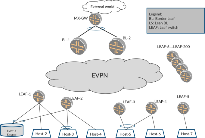
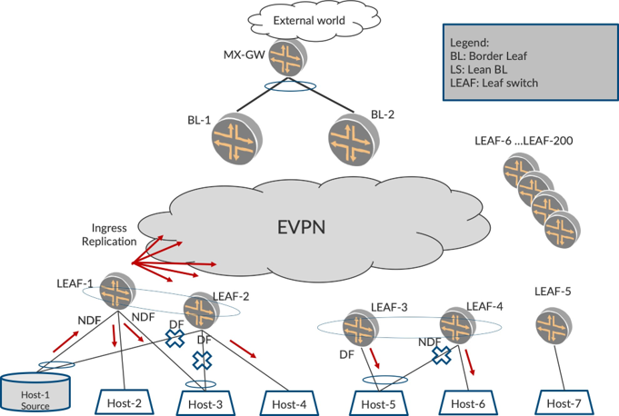
Physical Topology For an EVPN Fabric
Figure 1 illustrates a typical IP-CLOS physical topology. Typically, there are two Border LEAF devices (BL) and several LEAF devices (in the order of hundreds). Also, there are two (or four) Lean Spine (LS) devices that participate in the EVPN underlay for physical connectivity between devices in the EVPN fabric.
Typically, within the fabric, the multicast sources and hosts reside behind LEAF devices.
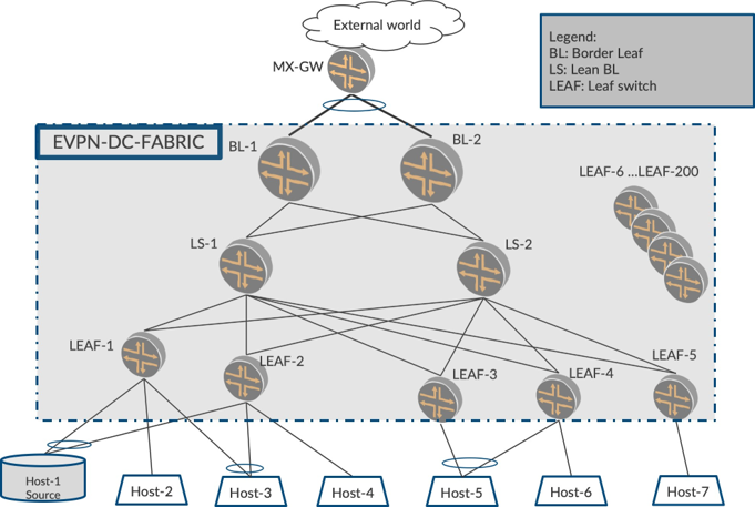
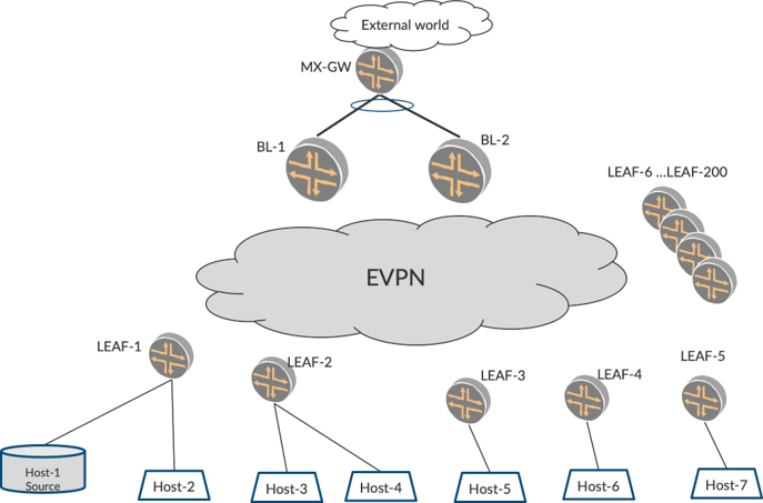
Logical Topology
For illustrating the procedures for non-optimized multicast in this chapter, Figure 2 shows a logical topology where an EVPN network is configured only on the BL and LEAF devices. Typically, the Lean Spine layer helps with underlay alone and is not configured with EVPN.
Initially, we will describe single-homed hosts. The LEAF devices from LEAF-6 to LEAF-200 have access links and have hosts behind them. To explain the principles and procedures, we will use LEAF-1 to LEAF- 5. The same procedures would apply to the rest of the LEAF devices, too.
Intra-subnet Multicast without Optimization
In this section, let’s explore the procedures for Intra-subnet multicast forwarding within the DC fabric on a single VLAN (L2-switched multicast). In this topology, there is only one VLAN, VLAN-101. Typically, four sets of behaviors have to be considered with respect to multicast forwarding. (The configuration for the EVPN devices is included later in this chapter.)
No sources and listeners exist
Sources do not exist, but listeners exist
Sources exist but no listeners exist
Sources and listeners exist
No Sources and Listeners Exist
This is straightforward in that it is a fabric with no multicast listeners or sources started yet.
Sources Do Not Exist but Listeners Exist
In this case, the listeners (hosts represented by Host-3 and Host-5 in Figure 3) are interested in traffic for a particular group G1, say 235.1.1.1. Since there is no multicast traffic started for that group yet, the listeners don’t receive any traffic.
Sources Exist but No Listeners Exist
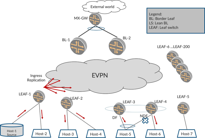
Consider a case where the multicast source (represented by Host-1 Source in Figure 3) has started to send the traffic for group G1, say 235.1.1.1, but there are no listeners yet for that group. In this case of intra-subnet multicast forwarding, the LEAF-1 that receives the multicast traffic will forward (L2-switch) the traffic to all the Layer 2 access interfaces on that VLAN. ie., towards Host-2. (SH-FWD). Also, LEAF-1 will not forward the traffic back to Host-1 based on Split Horizon. (ACCESS-SPLIT-HRZN).
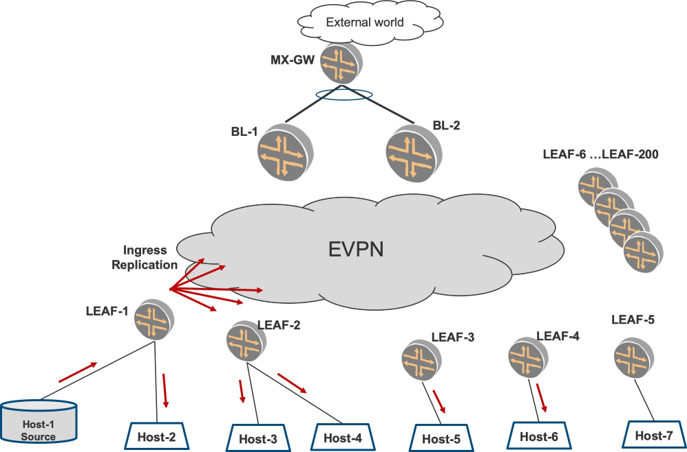
In Figure 3, LEAF-1 will forward the traffic towards the EVPN core to all the EVPN PEs using Ingress Replication. The PEs to which traffic is sent are determined by the remote PEs’ participation in the VLAN, VLAN-101. (CORE-IMET-FWD)
The participation of a LEAF in a VLAN is determined by virtue of EVPN Type-3s received from them. You can see all LEAFs except the LEAF-5 host, VLAN-101. Therefore, LEAF-5 would not send a Type-3 for VLAN-101. The multicast traffic will be Ingress Replicated to both BLs and all LEAFs except LEAF-5. (CORE-IMET-SKIP)
All the LEAF and BL devices that received the traffic from the EVPN core will forward this traffic onto all their access interfaces, irrespective of the presence of listeners as shown in Figure 3. LEAF-2 will forward towards Host-3 and Host-4. LEAF-3 will forward towards Host-5, and so on. Even when there are no listeners in the VLAN, you can see that the multicast traffic is ‘flooded everywhere’.
This may not be desirable because such a high volume of traffic unnecessarily flooding everywhere may affect bandwidth utilization in the core and the access interfaces of different EVPN devices in the fabric. Flooding is one of the characteristics of EVPN multicast without optimization. Later chapters describe how optimization procedures help address this flooding problem.
Sources Exist and Listeners Exist
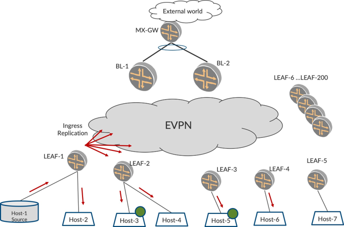
Consider the case where the source is sending traffic for group G1, say 235.1.1.1, and there are listeners in the fabric as shown in Figure 4. Therefore, Host-3 and Host-5 are interested in traffic for group G1 as shown. Listener interest is conveyed by the hosts by sending an IGMP report. Listener interest is represented in Figure 4 by a green circle on the host.
These IGMP hosts are expressing interest in traffic for group G1 from any source by sending IGMP report (*,G1). As described in the last section, by virtue of flooding multicast traffic everywhere, it reaches the interested listeners in the fabric and is consumed by them.
Intra-subnet Multicast in EVPN Multihomed Topologies
One of the advantages of EVPN deployment is the multihoming feature with Ethernet Segment Identifier (ESI). An ESI helps in grouping a set of links on different EVPN devices such that the devices that host a particular ESI will consider themselves multihomed on that ESI. This is achieved by the devices exchanging BGP EVPN Type 1 and Type-4 routes and deducing the multihomedness for the ESI.
Typically, the set of links that are grouped as an ESI are terminated on the CE in an aggregated Ethernet lag (AE) interface. Overall, the EVPN ESI paradigm will ensure redundancy and load balancing features from the multihomed PEs towards the CE. The AE interface bundle on the CE will ensure redundancy and load balancing features towards the multihomed PEs.
Overall, for the case of multihomed listeners, the objective is to ensure that the listeners do not receive duplicate copies of the same traffic. For the case of multihomed sources, the objective is to ensure that the traffic is not looped back towards the source. Consider the logical topology for EVPN Multihoming in Figure 5.
EVPN multihoming with ESI is a L2 feature. Therefore, two PEs are considered multihomed on an ESI (per VLAN per EVPN instance). This section describes how LEAF devices are multihomed. BL devices running PIM L3-routing being multihomed to tenant routers (titled as External Multicast) are described in detail in later chapters.
We shall describe this in order to illustrate the BUM forwarding rules:
Listener is behind multihomed LEAFs and source is single homed.
Source is behind multihomed LEAF.
Source is behind a LEAF that has multihomed listener on a different ESI.
Listeners Behind Multihomed LEAF Devices and Source are Singlehomed
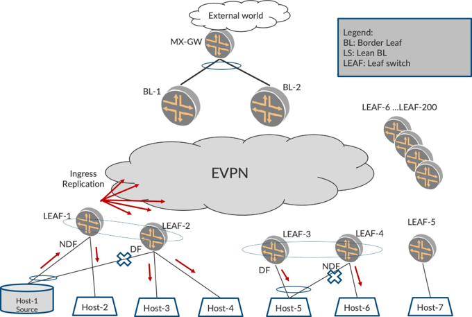
Consider the topology in Figure 6 where two LEAF devices, LEAF-3 and LEAF-4, are multihomed to Host-5. The rationale for multihoming Host-5 to LEAF-3 and LEAF-4 is that, in case of failure of one of the LEAFs, the traffic resumes over the other LEAF as soon as possible (resiliency). Also, if there are multiple unicast flows going from LEAF-1 to Host-5, some flows will be sent over LEAF-3 and others over LEAF-4 (load balancing).
For multicast traffic, care should be taken that the traffic from EVPN core is not sent by both LEAF-3 and LEAF-4, lest it result in duplicates for Host-5. (Duplicates are a worse problem for multicast applications than traffic loss!).
The Ingress LEAF, LEAF-1, will flood multicast traffic to both LEAF-3 and LEAF-4. Both LEAFs receive the traffic. However, only one LEAF should forward the traffic onto the ESI interface where they have realized the multihomed relationship.
To achieve this, the multihomed LEAFs determine the DF for a ESI amongst the PEs that are multihomed on that ESI. This determination is done by running a DF election algorithm (MOD based, local-preference, etc.,) based on Type-4 routes. Once this determination is completed, one amongst the multihomed PEs for the ESI is elected as the DF and the other multihomed PEs for that ESI are marked as NDF (non-DF).
When multicast traffic arrives from the EVPN core, rules for forwarding are as below:
On a single-homed access interface, flood the traffic.
On a multihomed access interface, if elected as DF, flood the traffic.
On a multihomed access interface, if marked as NDF, don’t flood the traffic.
In Figure 6LEAF-3 and LEAF-4, who are being multihomed towards Host-5 over an ESI, run an election for DF. Say LEAF-3 is elected as the DF and LEAF-4 is NDF for the ESI. When LEAF-3 receives traffic from the core (Ingress Replicated from LEAF-1), it floods to Host-5, since it is the DF on the ESI (CLASSICAL-DF-NDF).
LEAF-4, on receiving traffic from the EVPN core, does not flood the traffic towards Host-5 since it has marked the ESI as NDF (CLASSICAL-DF-NDF). Thus, Host-5 does not receive duplicates. LEAF-4, however, floods the traffic to Host-6 since it is a singly-homed access interface.
Multicast Source Behind Multihomed LEAF Devices
Consider Figure 7 where the multicast source is multihomed to two LEAF devices over an ESI where LEAF-1 is the NDF and LEAF-2 is the DF. When the source starts sending traffic, by virtue of an AE interface hashing, the traffic can be sent on either of the members of the LAG bundle. Therefore, Host-1 can send the traffic to either LEAF-1 or to LEAF-2.
Let’s say the multicast traffic is sent to LEAF-1. If no special handling for this scenario is undertaken, the following would occur based on (CLASSICAL-DF-NDF) procedures described earlier. LEAF-1 will send traffic towards the core. LEAF-2 on receiving this traffic from the core will flood on interfaces where it is the elected DF.
In this case, since LEAF-2 is the elected DF towards Host-1, it will end up forwarding back to the source. This is not correct behavior. Hence, special handling is required such that LEAF-2 does not send back the traffic on the ESI that it is multihomed to LEAF-1.
MPLS has the split-horizon label to handle such scenarios. How can this problem be addressed in VXLAN?
If it was possible for LEAF-2 to deduce that the packet was sent by LEAF-1, LEAF-2 can program its forwarding such that if packets come in from LEAF-1, it will skip forwarding on those interfaces that are multihomed with LEAF-1. Let’s examine this in detail.
LEAF-1 sends the multicast packets with the source-VTEP IP of LEAF-1, say S-VTEP-IP-1. LEAF-2 knows that LEAF-1 has S-VTEP-IP-1 as its source-VTEP from BGP Type-3 routes.
LEAF-2 walks its access interfaces/ESIs and builds a multihomed interface list with LEAF-1 where it is multihomed to LEAF-1. LEAF-2 then builds a rule in forwarding such that, when a packet arrives with SVTEP-IP-1, it will skip forwarding on this multihomed interface list with LEAF-1. Such forwarding rules are to be built for each LEAF that LEAF-2 is multihomed with. Let’s refer to this as (DST-LOCAL-BIAS).
With the forwarding being programmed, when LEAF-2 receives traffic from S-VTEP-IP-LEAF-1, the traffic is not sent back to the multihomed interface but flooded towards Host-3 and Host-4 (since these interfaces are not multihomed with LEAF-1).
Source is Behind a LEAF That Has a Multihomed Listener
Before we revisit the multihomed forwarding rules and rewrite the overall multicast L2 forwarding rules, we need to consider one more topology where an EVPN LEAF device has a local source and has a multihomed interface that are on different interfaces/ESIs.
Consider the topology shown in Figure 8 where LEAF-1 has a multicast source on a single-homed interface and a listener Host-3 on a multihomed interface shared with LEAF-2. Based on an election, let’s say that LEAF-1 is the NDF and LEAF-2 is the DF for the ESI.
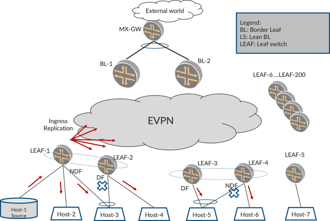
Per rules described earlier, LEAF-2, on receiving the traffic from the core, will not forward the traffic onto the multihomed interface list with LEAF-1. Therefore, LEAF-2 will not forward the traffic to Host-3.
LEAF-1 being the NDF towards Host-3 is an uncanny situation here. LEAF-2 will not forward the traffic to Host-3 due to (DST-LOCAL-BIAS). This is to ensure that traffic received on multihomed interfaces does not get looped back to the source. However, LEAF-1 being NDF towards Host-3 cannot forward to Host-3 based on (CLASSICAL-DF-NDF) rules. How is Host-3 to get traffic?
To address this scenario, let’s deviate a little from the (CLASSICAL-DF-NDF) rules. When LEAF-1 receives traffic from a local access interface, it will flood the traffic onto all the other local access interfaces irrespective of whether it is DF on the target interface or not. This can be referred to as (SRC-LOCAL-BIAS).
In Figure 8, LEAF-1 on receiving traffic from the source from the access interface will flood on all its access interfaces irrespective of DF/NDF. Therefore LEAF-1 will forward the traffic to Host-3 despite being NDF on the interface since the traffic arrived from an access interface. Thus, Host-3 will receive the traffic from LEAF-1.
LEAF-2 on receiving the traffic from the core from LEAF-1, will determine the s-VTEP to S-VTEP-IP-LEAF-1 and will skip forwarding to ‘MH interface list to LEAF-1’ (DST-LOCAL-BIAS). Thus, LEAF-2 will not forward to Host-3. LEAF-2 will forward to Host-4 since it is not a multihomed interface with LEAF-1.
Putting It All Together for Intra-VLAN Multicast
Based on the forwarding rules described so far in this chapter, let’s correlate the behavior in our sample topology vis-à-vis the forwarding rules. Please refer to the Traffic Verification section for statistics.
In Figure 9 LEAF-1 is the NDF on the MH-interfaces that go to Host-1 and Host-3. LEAF-3 is the DF on the MH interface that goes to Host-5. Host-1 is the source of multicast traffic. Host-1, based on the hash of its AE bundle, can send the traffic to either LEAF-1 or LEAF-2. Say it sends to LEAF-1.
Here, LEAF-1 performs the actions below:
Does not send the traffic back to Host-1 (ACCESS-SPLIT-HRZN)
Ingress Replicates traffic to all remote PEs over VTEP (CORE-IMET-FWD)
Does not send to LEAF-5 as no Type-3 for VLAN-101. (CORE-IMET-SKIP)
Sends traffic to Host-2 since it is single-homed interface (SH-FWD)
Sends to Host-3, though it is NDF and it is access traffic (SRC-LOCAL-BIAS)
LEAF-2, on receiving the traffic from core, performs the actions listed below:
Does not send traffic back to core (CORE-SPLIT-HRZN)
Sends traffic towards Host-4 since it is a single-homed interface. (SH-FWD)
Does not send traffic to Host-1 (DST-LOCAL-BIAS)
Does not send the traffic to Host-3 (DST-LOCAL-BIAS)
LEAF-3, on receiving traffic from core, performs the actions below:
Sends to Host-5 since it is DF on that interface (CLASSICAL-DF-NDF).
LEAF-4, on receiving traffic from core, performs the actions below:
Does not send to Host-5 since it is NDF (CLASSICAL-DF-NDF).
Forwards the traffic to Host-6 since it is a single-homed interface (SH-FWD).
LEAF-5 does not receive traffic from core since it does not host VLAN-1.
Overall Forwarding Rules For Multicast Traffic in EVPN
Let's enhance the rules stated earlier in this chapter and take multihomed into account.
(CLASSICAL-DF-NDF)
When traffic arrives from EVPN core from a PE who I am not multihomed with
On a single-homed access interface, flood the traffic.
On a multihomed access interface, if elected as DF, flood the traffic
On a multihomed access interface, if marked as NDF, don’t flood the traffic
(DST-LOCAL-BIAS)
When traffic arrives from EVPN core from a PE, say PE-X, who I am multihomed with
On a single-homed access interface, flood the traffic.
On a multihomed access interface where multihomed with PE-X, don’t flood traffic, irrespective of DF/ NDF.
On a multihomed access interface where not multihomed with PE-X, flood if I am DF on that interface.
On a multihomed access interface where not multihomed with PE-X, do not flood if I am NDF on that interface.
(SRC-LOCAL-BIAS)
When traffic arrives from access interface:
Flood on all the other access interfaces irrespective of DF/NDF.
Ingress Replicate to core to all PEs that host the VLAN.
The above procedures, (2) and (3), for forwarding BUM traffic are generally referred to as local-bias. As the name suggests, when traffic arrives on a local access interface, the LEAF device is given the bias to forward it onto other access interfaces irrespective of DF/NDF. The remote multihomed devices do not forward onto the multihomed access interface irrespective of DF/NDF. Therefore, the local PE is given preference to forwarding over the remote PE (hence the term local-bias).
We have to keep in mind that these rules of local bias are applicable only in EVPNoVXLAN. With EVP-NoMPLS, the usage of the split-horizon label per ESI addresses the multihomed scenarios.
The procedures for split-horizon label are beyond the scope of this book.
Chapter Summary
This chapter has explored different BUM forwarding rules in single-homed and multihomed topologies. We illustrated how multicast traffic is flooded everywhere throughout the EVPN fabric towards the core and all access interfaces. Multihoming forwarding rules help to ensure that listeners do not receive duplicates or are looped back. These rules take into account the DF/NDF status of an ESI, whether the traffic arrived from a PE with which it is multihomed, and whether traffic arrived on an access interface.
Assisted Replication chapter explores the challenges with Ingress Replication and how it can be mitigated. Configurations and verifications now follow.
Configuration
Figure 10 is the reference topology.
Now let’s focus on the configuration and verification of the intra-VLAN Multicast functionality described in this chapter, including multihoming in EVPNoVXLAN and the commands used. In this section, we will see the EVPN intra-VLAN multicast traffic forwarding behavior, particularly the flood everywhere aspect in the absence of any optimizations.
The basic underlay and overlay configurations listed in EVPN Base Configuration in DC Fabric Topology chapter are sufficient for this section. For all of our intra VLAN discussions, we will focus on VLAN-101(VLAN id 101, VNI 101). Please note that LEAF-5 does not Host VLAN-101/VNI-101.
Traffic Verification
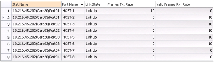
From Host-1, start sending multicast traffic at 10 pps (packets per second) for group 225.1.1.1 in VLAN-101. Note that, as of now, no receivers have actually expressed interest in receiving this traffic.
From the RT statistics in Figure 11, you can see that Host-1 sends traffic at 10 pps, which is received by all the Hosts within the DC that are part of VLAN-101 (Host-2 to Host-6), though none of them are interested in the traffic. Host-7 alone, which is not part of VLAN-101, is spared from the traffic. Host-8 is outside of the fabric and it can be ignored for now.
Multicast Traffic Outputs - LEAF-1
Host-1 is multihomed to LEAF-1 and LEAF-2. So the traffic from Host-1 towards LEAF-1/LEAF-2 may be load balanced and can arrive on either LEAF-1 or LEAF-2. In our case, the multicast traffic arrives on access interface, ae0 on LEAF-1.
The traffic is not flooded back on the incoming interface, ae0.0: (ACCESS-SPLIT-HRZN).
On LEAF-1, the traffic is forwarded on the other single-homed access interface, xe-0/0/4 towards Host-2: (SH-FWD).
The traffic is forwarded on all multihomed access interfaces, ae1.0 on LEAF-1, irrespective of the DF/NDF status (SRC-LOCAL-BIAS):
lab@LEAF-1> monitor interface traffic detail
Interface Link Input packets (pps) Output packets (pps) Description
…
 xe-0/0/4  Up       0         (0)      2474        (10)   TO Host-2
…
 ae0       Up      2467       (10)       0          (0)     TO CE-1
 ae1       Up       0          (0)     2470        (10)     TO CE-2
…
The multicast traffic is also forwarded on the VTEPs towards BL-1 (101.101.101.101) and BL-2 (102.102.102.102).
Also forwarded on the VTEPs towards LEAF-2 (106.106.106.106), LEAF-3 (107.107.107.107), and LEAF-4 (108.108.108.108): (CORE-IMET-FWD).
The traffic is not forwarded on the VTEP towards LEAF-5 (109.109.109.109) (CORE-IMET-SKIP):
lab@LEAF-1> show interfaces vtep extensive | grep “VXLAN Endpoint Type: Remote|Output packets.*pps”
    VXLAN Endpoint Type: Remote, VXLAN Endpoint Address: 106.106.106.106…
     Output packets:                2488                     9 pps
    VXLAN Endpoint Type: Remote, VXLAN Endpoint Address: 101.101.101.101…
     Output packets:                2488                     9 pps
    VXLAN Endpoint Type: Remote, VXLAN Endpoint Address: 108.108.108.108…
     Output packets:                2488                     9 pps
    VXLAN Endpoint Type: Remote, VXLAN Endpoint Address: 107.107.107.107…
     Output packets:                2489                    10 pps
    VXLAN Endpoint Type: Remote, VXLAN Endpoint Address: 109.109.109.109…
     Output packets:                   0                     0 pps
    VXLAN Endpoint Type: Remote, VXLAN Endpoint Address: 102.102.102.102…
     Output packets:                2489                    10 pps
Multicast Traffic Outputs - LEAF-2
The multicast traffic arriving on LEAF-2 is not forwarded on the multihomed access interfaces, ae0 and ae1, although it is the DF on both of these interfaces since the source PE, LEAF-1, is a multihomed peer on the ESI of these interfaces (DST-LOCAL-BIAS). This ensures that there is no looping of traffic towards the multihomed source, Host-1, and no traffic duplication towards the multihomed Host, Host-3.
The traffic is forwarded on xe-0/0/4.0 (SH-FWD) towards the single-homed Host, Host-4:
lab@LEAF-2> monitor interface traffic detail
Interface Link Input packets (pps) Output packets (pps) Description
…
 xe-0/0/4  Up       0         (0)      2478        (10)   TO Host-4
 ae0       Up      553        (0)       213         (0)     TO CE-1
 ae1       Up       0         (0)       208         (0)     TO CE-2
…
The traffic is not sent back on any of the VTEPs. Though VTEPs are part of the flood next hop, the split horizon rules for BUM traffic arriving from a core ensure that the traffic is not sent back to the core. (CORE-SPLIT-HRZN).
Multicast Traffic Outputs - LEAF-3
The traffic arriving on LEAF-3 is not forwarded on the multihomed access interface, ae0.0, since it is the NDF (CLASSICAL-DF-NDF). This ensures that the multihomed Host, Host-5, does not receive duplicate traffic:
lab@LEAF-3> monitor interface traffic detail
Interface Link Input packets (pps) Output packets (pps) Description
…
 ae0       Up       0         (0)       208        (0)      TO CE-3
…
The traffic is also not sent back on any of the VTEPs (CORE-SPLIT-HRZN).
Multicast Traffic Outputs - LEAF-4
The multicast traffic arriving on LEAF-4 is forwarded on the multihomed access interface, ae0.0, since it is the DF and LEAF-1 is not a multihomed peer (see section 3.4.1): (CLASSICAL-DF-NDF).
The traffic is also forwarded on xe-0/0/3.0 (SH-FWD) towards the single-homed Host, Host-6:
lab@LEAF-4> monitor interface traffic detail
Interface Link Input packets (pps) Output packets (pps) Description
…
 xe-0/0/3  Up       0         (0)     2480         (10)   TO Host-6
 ae0       Up      505        (0)     2481         (10)     TO CE-3
…
The traffic is not sent back on any of the VTEPs (CORE-SPLIT-HRZN).
Multicast Traffic Outputs - LEAF-5
LEAF-5, since it does not Host the VLAN-101, does not receive the traffic from LEAF-1 at all.
Multicast Traffic Outputs –BL-1 and BL-2
The behavior of the two border LEAF devices will become significant only once we reach the chapter about inter-VLAN traffic forwarding. So until then, we will ignore the traffic forwarding behavior on these devices.
Detailed Control Plane Verification
Verifying the Flood Routes
For each VLAN, a PE builds a flood next hop consisting of all its access interfaces for that VLAN, and the VTEPs corresponding to the EVPN peers from which it has received Type-3 routes for that VLAN. This next hop is used to flood the multicast traffic in the VLAN.
For instance, on LEAF-1, the flood next hop is comprised of VTEPs corresponding to:
BL-1 (vtep.32770)
BL-2 (vtep.32774)
LEAF-2 (vtep.32769)
LEAF-3 (vtep.32772)
LEAF-4 (vtep.32771)
The VTEP corresponding to LEAF-5 (vtep.32773) is not present in the flood next hop for VLAN-101.
lab@LEAF-1> show ethernet-switching flood route re-flood bridge-domain VLAN-101
  Flood route prefix: 0x30000/51
  Flood route type: RE_FLOOD
  Flood route owner: __re_flood__
  Flood group name: __re_flood__
  Flood group index: 65534
  Nexthop type: comp
  Nexthop index: 1735
    Flooding to:
    Name        Type NhType Index
    __all_ces__ Group comp   1734
       Composition: split-horizon
       Flooding to:
       Name       Type NhType Index
       xe-0/0/4.0 CE   ucst    1732
       ae1.0      CE   ucst    1715
       ae0.0      CE   ucst    1714
    Flooding to:
    Name    Type  NhType Index
    __ves__ Group comp    1724
        Composition: flood-to-all
        Flooding to:
        Name       Type        NhType Index
        vtep.32769 CORE_FACING venh    1751
        vtep.32770 CORE_FACING venh    1756
        vtep.32771 CORE_FACING venh    1761
        vtep.32772 CORE_FACING venh    1762
        vtep.32774 CORE_FACING venh    1765
The flood next hop information on the other PEs will be similar to the above.
Verification of Multihoming State
Each PE Hosting the ES, performs a DF election for the ES.
For the active/active Ethernet segments multihomed to LEAF-1 and LEAF-2, therefore, 00:11:11:11:11:11:11:11:11:11 and 00:22:22:22:22:22:22:22:22:22, LEAF-2 (106.106.106.106) is elected DF.
For the active/active Ethernet segment multihomed to LEAF-3 and LEAF-4, i.e. 00:33:33:33:33:33:33:33:33:33, LEAF-4 (108.108.108.108) is elected DF.
In most cases we will verify the states for a single ESI on LEAF-1 by itself. The states for other ESIs and on other PEs are similar and are left as an exercise for the reader.
DF Verification
Let’s verify the DF/NDF state on LEAF-1:
lab@LEAF-1> show evpn instance designated-forwarder esi 00:11:11:11:11:11:11:11:11:11
…
    ESI: 00:11:11:11:11:11:11:11:11:11
      Designated forwarder: 106.106.106.106
lab@LEAF-1> show evpn instance designated-forwarder esi 00:22:22:22:22:22:22:22:22:22
…
    ESI: 00:22:22:22:22:22:22:22:22:22
      Designated forwarder: 106.106.106.106
Verification For ESI Status in Detail
The following command may be used to see more details on the DF election for an ES:
lab@LEAF-1> show evpn instance esi 00:11:11:11:11:11:11:11:11:11 extensive
…
  Number of local interfaces: 4 (4 up)
   Interface name ESI                           Mode         Status AC-Role
   .local..4      00:00:00:00:00:00:00:00:00:00 single-homed Up        Root
   ae0.0          00:11:11:11:11:11:11:11:11:11 all-active   Up        Root
   ae1.0          00:22:22:22:22:22:22:22:22:22 all-active   Up        Root
   xe-0/0/4.0     00:00:00:00:00:00:00:00:00:00 single-homed Up        Root
…
   ESI: 00:11:11:11:11:11:11:11:11:11
     Status: Resolved by IFL ae0.0
     Local interface: ae0.0, Status: Up/Forwarding
     Number of remote PEs connected: 1
       Remote PE       MAC label Aliasing label Mode
       106.106.106.106 0         0              all-active
     DF Election Algorithm: MOD based
     Designated forwarder: 106.106.106.106
     Backup forwarder: 105.105.105.105
…
Router-ID: 105.105.105.105
…
Verifying ESI State: Forwarding/Blocked
Now let’s verify the ESI state.
LEAF-1, since it is not the DF on multihomed access interfaces ae0.0 and ae01, marks them in “Blocking” mode for BUM traffic, while LEAF-2, being the DF, marks these interfaces in “Forwarding” mode:
lab@LEAF-1> show interfaces ae0.0 extensive
…
… EVPN multi-homed status: Blocking BUM Traffic to ESI, …
…
  Local Bias Logical Interface Name: vtep.32769, Index: 558, VXLAN Endpoint Address: 106.106.106.106
lab@LEAF-2> show interfaces ae0.0 extensive
…
… EVPN multi-homed status: Forwarding, …
…
  Local Bias Logical Interface Name: vtep.32769, Index: 556, VXLAN Endpoint Address: 105.105.105.105
The PE(s) to which this interface is multihomed can also be seen in the output. This information is used on this PE when applying the DST-LOCAL-BIAS for traffic arriving from the core.