EVPN Inter-VLAN Multicast Routing without Optimization
Part 2 of this book explored how Intra-VLAN multicast works in an EVPN data center fabric. It also explored different optimization procedures like IGMP-snooping, Selective (SMET) Forwarding, and Assisted Replication (AR). These procedures are about traffic forwarding rules within a VLAN.
Traditionally, customers have several VLANs in their data center fabric, for example, an Admin department in VLAN-A, Payroll in VLAN-B, Engineering in VLAN-C, etc. In IPTV applications, a set of subscribers may be hosted in one VLAN and another set in another VLAN and so on. The number of VLANs in an EVPN fabric can range from 20 to around 1000.
There may be a need to forward multicast traffic across VLANs. The sources of the multicast traffic may be present in some VLANs, while listeners may be present in some or all VLANs. There may be a need for routing the multicast traffic from one VLAN to the interested listeners in other VLANs.
PIM has been the de facto protocol for Inter-VLAN multicast routing and operates at the Level 3 layer. For inter-subnet multicast, we will first describe how PIM on an external M-Router can be used to achieve multicast routing across the VLANs in the fabric. Then we will describe how L3 routing can be achieved by running L3 multicast routing with PIM on IRB on the EVPN device itself.
The model that we will describe is called Centrally Routed Bridged (CRB) model for multicast, where routing is performed in a central device as opposed to performing routing in the Edge Routed Bridge (ERB) model. It may be worth noting that unicast can be configured to work in an ERB model, while multicast routing is configured to work in a CRB model.
By the end of this chapter, you should have a fair understanding of:
Inter-subnet multicast in an EVPN data center fabric using External M-Router.
Inter-subnet Multicast in an EVPN data center with L3-PIM routing on devices with IRB.
How the ‘flood eveywhere’ problem is compounded with Inter-VLAN multicast.
We also describe the procedures of Inter-Subnet Multicast Routing without any Intra-VLAN optimization. This is first to illustrate the procedures for Inter-VLAN multicast alone, and how the problem of ‘flood everywhere’ is compounded manifold in Inter-VLAN scenarios.
In EVPN Inter-VLAN Multicast Routing with Optimization chapter we throw in the optimization techniques of IGMP-snooping, Selective Forwarding, and Assisted Replication, and illustrate the bandwidth conservation that can be achieved through using those techniques.
Inter-subnet Multicast
There are two ways L3 inter-subnet multicast can be deployed:
Perform L3-routing on a peripheral device (External M-Router/Tenant Router)
Perform L3-routing on a device that is part of the fabric using IRB
Though (b) is the preferred and widely deployed method for Inter-subnet multicast, (a) is sometimes used to achieve the same result when devices in the fabric do not support IRB routing, or, if for security reasons, operators prefer L3-routing of multicast on a peripheral device. Once we have finished exploring (a) in the next section, later chapters and sections will focus on (b).
Inter-subnet Multicast with External Multicast Router
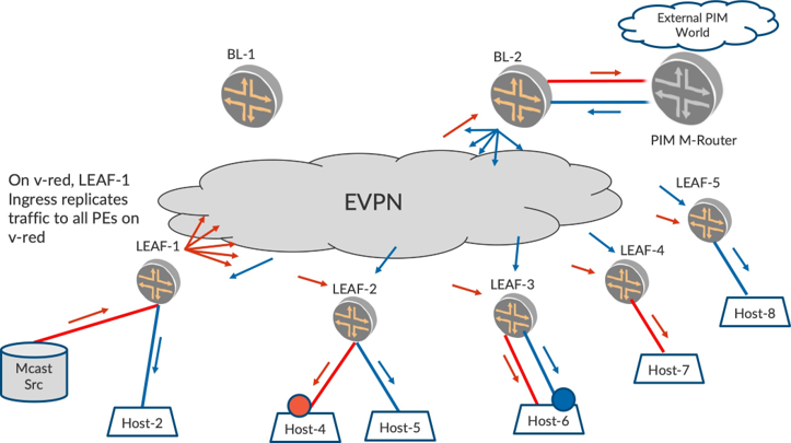
Consider the topology depicted in Figure 1. A data center fabric has two VLANs, v-red and v-blue. The Border Leaf (BL) devices do not perform L3-multicast routing but may perform unicast routing (achieved by configuring IRB with routing protocols for unicast but not enabled with PIM on the IRB interface).
There is a ‘PIM M-Router’ device on the periphery of the fabric that is assigned the responsibility for L3-inter-subnet multicast routing for the fabric. One of the EVPN devices, BL-2, is connected to the PIM M-Router. BL-2 and the PIM M-Router host all VLANs in the fabric and BL-2 L2 switches the traffic and listener interest from fabric to the PIM M-Router.
Bridge Domains (BDs) Not Everywhere
It is worth noting that the LEAF devices need not host all the VLANs in the fabric. For example, LEAF-1 can host VLANs 1 to 50, while LEAF-2 can Host VLANs 20 to 70, and so on. Still, multicast routing will work between the source-VLAN to the listener VLANs as long as the BL-2 and the PIM M-Router host all the VLANs in the fabric.
In Figure 1, the multicast source is on v-red behind LEAF-1. There are hosts Host-2, Host-4, Host-5, and Host-6 that have v-blue. Also, hosts Host-4, Host-6, and Host-7 have v-red. It can be observed that LEAF- 1, LEAF-2, and LEAF-3 host both VLANs, while LEAF-4 and LEAF-5 do not host all the VLANs..
No Source or Listeners Started
If there are not listeners and sources in any of the VLANs, there is nothing to do.
Source Alone Starting Up On v-red
There are no listeners anywhere in the fabric. This is similar to what we have seen when the traffic on v-red is flooded to all the PEs and the access interfaces on v-red. Also, this traffic is flooded by BL-2 towards M-Router.
Listeners alone coming up
Say there is no traffic started and there are listeners coming up for group G1 on v-red from Host-4 and on v-blue from Host-6 (shown in Figure 1 by circles). These reports are sent across the EVPN core and reach the BL-2, are sent to the PIM M-Router, and create PIM states on this M-Router device for (*,G1) on both VLANs, blue and red.
Source started on v-red and listeners on v-red and v-blue
By virtue of listener interest for group G1 on v-red from Host-4 and on v-blue from Host-6, PIM (*,G1) states are created on the PIM M-Router. When the source starts sending traffic on v-red, this traffic reaches the PIM M-Router device on v-red. This PIM M-Router device routes the multicast traffic from the v-red to v-blue.
Post routing, the M-Router device forwards the packet on v-blue. This traffic reaches BL-2 and gets flooded towards the EVPN core on v-blue. The LEAFs that host v-blue receive the traffic and flood it to the listeners; LEAF-1, LEAF-2, LEAF-3, and LEAF-5 flood the traffic received on v-blue to Host-2, Host-5, Host-6, and Host-8, respectively. It is worth noting that the LEAF devices flood the traffic to hosts irrespective of active listener interest.
If we have several VLANs (say, v-orange, v-green, etc.), and there is at least one listener in each of these VLANs, the traffic will get routed by the M-Router from v-red onto all the listener VLANs. Also, post routing, the routed multicast traffic will be forwarded towards the EVPN core onto all the listener VLANs.
Flooding and Multicast Traffic Hair-pinning
Let’s take a closer look at LEAF-1.
It can be observed that LEAF-1 floods the traffic on v-red. This traffic goes to the M-Router and gets routed onto v-blue and returns to LEAF-1. Then LEAF-1 floods the traffic to v-blue access interfaces. The multicast traffic has to hop to the periphery of the data center fabric to get routed and has to return via the fabric to the interested listeners.
This is a characteristic of CRB-Multicast. The main reason for deployment of CRB-Multicast routing is that since the central device (BL-2) performs the Multicast routing, the LEAFs are_not required to host all the VLANs.
Also, since Snooping/Selective forwarding is turned off, LEAF-2 and LEAF-5 forward traffic to Host-5 and Host-8 on v-blue, even though there is no listener interest for group G1. Also, BL-2 forwards traffic to all LEAFs irrespective of the presence of listener interest behind them.
It is worth noting that with optimizations in multicast, the ‘flood everywhere’ aspect of the problem can be addressed. Overall, with optimizations, the following are possible with AR, SMET forwarding, and IGMP-snooping:
the core-bandwidth utilization can be conserved on each VLAN
the link bandwidth utilization can be conserved on each VLAN
the access side link utilization can be conserved on each VLAN
the replication load on LEAF and BLs is reduced for each VLAN
However, the issue of inter-subnet multicast traffic hopping all up until M-Router and returning back to the LEAFs (‘hair-pinning’) cannot be alleviated with the optimizations.
It may make sense here to explain that the alternative to the ‘hair-pinning’ problem is ERB Multicast. However, it has several nuances that have to be taken into consideration when it comes to scenarios of BDs-not-everywhere, External Multicast, and the need for PIM and IRB on all participating devices.
Since with CRB-Multicast, (a) BDs-not-everywhere is allowed, (b) PIM is required on only one device, and (c) External Multicast works seamlessly and uses traditional PIM procedures, CRB-Multicast is preferred for deployments today. Also, since the ‘flood everywhere’problem is mitigated significantly with the optimizations in Part I of this book, applications today can be effectively run with CRB-Multicast.
Inter-subnet Multicast with PIM and IRB On Spines
In an earlier section, we explored how inter-subnet multicast is achieved with the use of an external M-Router placed in the periphery of the EVPN data center fabric. In this section, let’s explore how we can have L3-routing PIM on IRB functionality on BL devices within the fabric (see Figure 2). This approach is preferred over using M-Router, because the need for an external M-Router is obviated and existing participating EVPN BLs take up the role of L3-PIM multicast routing. Also, the number of hops the packets are subjected to is reduced. Additional enhancements for optimization become possible with this model.
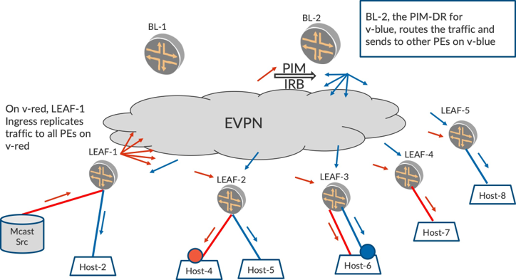
In Figure 2 the PIM L3-routing functionality can be performed on BL-2 itself, instead of a PIM M-Router. For this to work, BL-2 has to host all the VLANs in the fabric and has to be enabled with PIM on IRBs for all the participating VLANs.
The routing of the multicast traffic from v-red to v-blue will be performed by BL-2 as BL-2 is the PIM DR for v-blue. Post routing, BL-2 will flood the traffic on v-blue to all LEAFs, and in turn to the access interfaces LEAFs that are on v-blue. The traffic forwarding on LEAFs is similar that discussed earlier in this chapter.
The earlier section related to Flooding and Traffic Hair-pinning is applicable in this scheme as well. For example, the traffic on v-red has to reach BL-2, get routed onto other listener VLANs, and return to the LEAFs.
An IRB Multicast Primer
When a multicast L2-frame reaches an EVPN device on a VLAN that has IRB enabled on that VLAN, the multicast L2-frame is L2-switched to other access interfaces on the EVPN device on that source-VLAN.
In addition, the L2-headers are removed and the L3-packet inside is punted to the L3-component of the IRB interface of that VLAN. This will make it appear as if the L3-packet has reached the IRB interface on the EVPN device. From this point on, the L3 procedures will apply on the packet that arrived on IRB interface.
Consider Figure 2 where there are listeners on v-blue at Host-6. When these IGMP reports (multicast L2-frames) reach SPINE-2, the L3-IGMP report will be punted to IRB interface on v-blue on BL-2. This will lead to IGMP and PIM (*,G1) state creation on IRB.blue on BL-2.
When Mcast Src starts sending traffic on v-red, this traffic reaches BL-2 and is punted to IRB.red. Now PIM L3-multicast routing occurs on BL-2, therefore traffic from IRB.red is routed to IRB.blue using PIM. Post routing into IRB.blue, the traffic is Ingress replicated on v-blue to all EVPN PEs that participate in v-blue.
Thus the multicast traffic reaches the LEAF devices on v-blue and the LEAF devices in turn flood the routed packets on v-blue to all the access interfaces.
To achieve this, PIM needs to be enabled on IRB interfaces on the BL devices. IRB interfaces are the representative interfaces of a L2-bridge domain. Typically, there is a VLAN/bridge-domain and it has multiple L2-interfaces associated with the BD. When traffic arrives on the L2-interface for that BD, traditional L2-switching occurs on that VLAN. In addition, L3-layer functionality of unicast route lookup or multicast routing with PIM occurs at the IRB interface.
All PIM-related procedures and protocols are applicable on IRB interfaces. So BL-1 and BL-2 see each other as PIM neighbors on each of the IRB interfaces (VLANs). By virtue of EVPN emulating a LAN, the IRB interface acts as the L3-interface towards the LAN for the spine devices. PIM Joins/Hellos are sent and received over the IRBs and PIM DRs are also elected.
Inter-subnet Multicast with Multiple VLANs
In earlier sections we described how Inter-subnet multicast works between two VLANs. Typically, in multicast applications, there will be several VLANs where there are interested listeners for the group G1. When the traffic for the group arrives, this source-traffic is routed onto all VLANs using multicast IRB procedures and forwarded onto the listener IRBs and Ingress replicated on all the interested VLANs.
If a single BL takes the load for routing traffic onto all VLANs, then that BL will be overloaded. It is desirable that the L3-routing load is shared across multiple BL devices.
Towards this end, two BLs are typically deployed for PIM L3-routing purposes. Classical PIM procedures are utilized to elect PIM DR for different VLANs. Therefore, for some set of VLANs, BL-1 will be the PIM DR while for other VLANs, BL-2 will be the PIM DR. The BL that is the non-DR (NDR) on the listener IRB will not route the traffic onto that VLAN.
Something to Remember About PIM DR-ship
PIM DR-ship is always relevant when building the outgoing interface list. The responsibilities of a PIM device that is a PIM DR on an IRB.600 are:
When traffic arrives on that IRB.600, register the source to the PIM-RP.
When an IGMP report is received on IRB.600 for group G1, create a PIM (*,G1) Join state on IRB.600.
When traffic arrives on any other IRB, say IRB.800, if there are listeners on IRB.600, then route the traffic from IRB.800 to IRB.600 and Ingress replicate the traffic on VLAN 600 to other PEs that Host VLAN-600.
PIM DR election, by default, is based on the IP address of the BL devices. The BL with the highest IP address on a particular IRB interface is elected as the DR. It may be that the IP address of one BL device is always higher on all IRBs. In this case, to effectively load-balance across VLANs, it is a good idea to configure the DR priority value under the IRB.
Configuring the DR priority value on an IRB interface will cause the DR-priority value to be carried in the PIM hello message. This DR-priority value will override the DR election based on IP address. This way, different L3-PIM BL devices can be configured as the DR for different IRBs.
An Example with Multiple Spines Sharing Load Using PIM DRship
Let’s consider a topology like Figure 3, where there are three VLANs. VLAN v-red has a multicast source behind LEAF-1. There are two other VLANs, v-blue and v-green, where there are listeners behind some LEAFs. BL-1 is the PIM DR for v-red and v-blue, and BL-2 is the PIM DR for v-green.
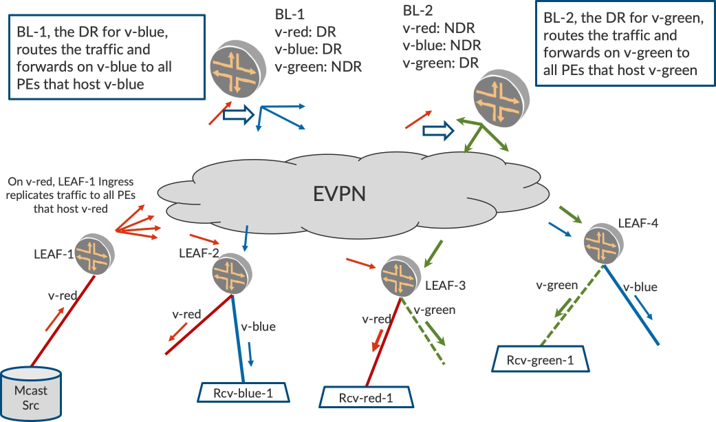
When IGMP reports are received on v-blue, the BL-1 (PIM DR for v-blue) creates PIM (*,G) state for IRB. blue. Similarly, when IGMP reports are received on v-green, the BL-2 (PIM DR for v-green) creates PIM (*,G) state for IRB.green.
When Mcast Src sends traffic on IRB.red, the L2-switching based forwarding will ensure that traffic is forwarded everywhere on v-red. When traffic arrives on BL-1 on v-red (IRB.red), BL-1 will L3-route the traffic onto v-blue (since it is the DR for v-blue). Post routing, BL-1 will Ingress replicate the packet onto v-blue to all PEs that host v-blue. BL-1, being the non-DR for v-green will not route the packet onto v-green.
Similarly, when BL-2 receives the traffic on v-red (IRB.red), it will L3-route the traffic onto v-green (since it is the DR for v-green). Post routing, BL-2 will Ingress replicate the packet onto v-green to all PEs that Host v-green. BL-2, being the non-DR for v-blue, will not route the packet onto v-blue.
Thus multiple BLs are used to load share the role of PIM L3-routing in the fabric. In a fabric with, say, 100 VLANs, BL-1 may be PIM DR for VLANs 1-50 and BL-2 may be DR for VLANs 51-100. BL-1 routes the traffic onto 50 VLANs while BL-2 does so for the rest.
Flood-everywhere Problem Compounded with Inter-subnet Multicast
Kindly note that since there is no optimization in use so far, the L2-switched traffic is forwarded everywhere on the source-VLAN. On the receiving VLANs, as long as there is a _single receiver existing, a PIM (*,G) join state gets created on the BL and this results in the BL routing the traffic onto that receiver VLAN.
This results in all the PEs that host the receiver-VLAN getting the traffic, and these PEs in turn forwarding the traffic onto the access interfaces irrespective of whether there are existing listeners or not. That is to say, the non-optimized multicast paradigm to flood everywhere in Intra-VLAN multicast is compounded in Inter-subnet multicast scenarios when the routed traffic is flooded everywhere, too. In later chapters we discuss how optimized multicast mitigates this flooding of traffic.
For now, let’s briefly take a typical use case and describe the bandwidth calculations. Consider the following use case where optimizations are turned off:
Number of LEAFs in Fabric: ‘N’ = 200
Number of groups: ‘G’ = 20
Traffic Rate: ‘R’ = 1 pps Number of VLANs ‘M’ = 500
The core-bandwidth utilization on the source-VLAN will be:
(N * G * R) = (200 * 20 * 1) = 4 Kbps
The routed multicast traffic is sent to all the VLANs. The core-bandwidth utilization of the Fabric will be:
(N * G * R * M) = (200 * 20 * 1 * 500) = 2 Mbps
This is increasingly referred to as the (M * N) replication problem where ‘M’ is the number of VLANs and ‘N’ is the number of LEAFs that the traffic has to be replicated to. Without optimization, on each of the ‘M’ VLANs the traffic is flooded to each of the ‘N’ LEAFs. Also, on each LEAF, traffic is flooded onto the access interfaces on each of the ‘M’ VLANs.
Chapter Summary
This chapter explored the mechanism of Inter-VLAN multicast in an EVPN data center fabric. We turned OFF the optimizations to illustrate how the problems with non-optimized multicast get compounded with multiple VLANS in the fabric. In the next chapter, we illustrate how the optimizations play a significant role in mitigating the ‘flood everywhere’ problem.