ON THIS PAGE
Access Juniper Security Director Cloud and Check Active Subscriptions
Generate Device Certificates in Juniper Security Director Cloud
Deploy a Secure Edge Policy in Juniper Security Director Cloud
Gather IPsec Tunnel Configuration Parameters to Apply in Juniper Security Director Cloud
Verify the IPsec Tunnel from Mist to Juniper Secure Edge (Manual)
Configure Secure Edge Connector with Juniper Secure Edge (Manual)
This topic outlines every step of the workflow to manually provision Secure Edge Connector with Juniper® Secure Edge.
The Juniper Mist cloud integrates with Juniper Secure Edge (JSE) to inspect traffic from WAN Edge devices. The Secure Edge Connector configuration in Mist enables Session Smart Routers and SRX Series Firewalls deployed as a WAN Edge device to send a portion of traffic to JSE for inspection.
Secure Edge capabilities are managed by Juniper Security Director Cloud, Juniper’s simple and seamless management experience delivered in a single user interface (UI).
For more information, see Juniper Secure Edge.
Configuration Overview
In this task, you send the Internet-bound traffic from the LAN side of a spoke or hub device to the Secure Edge for inspection before the traffic reaches the Internet.
The topics in the following table present the tasks you need to complete in order to integrate the Mist cloud with JSE to inspect WAN Edge device traffic by way of the Secure Edge Connector. The order that the tasks are listed represents the sequence of steps you should follow to complete the workflow.
| Step | Task | Description |
| 1 | Access Juniper Security Director Cloud and Check Active Subscriptions | Access Juniper Security Director Cloud, go to your organization account, and check Secure Edge subscriptions. The subscription entitles you to configure Secure Edge services for your deployments. |
| 2 | Configure a Service Location in Juniper Security Director Cloud |
Create service locations. This is where VPN gateways create secure connections between different networks. |
| 3 | Generate Device Certificates in Juniper Security Director Cloud | Generate digital certificates for Juniper Secure Edge to establish secure communications between Secure Edge and user endpoints. |
| 4 | Create an IPsec Profile in Juniper Security Director Cloud | Create IPsec profiles to establish IPsec tunnels for communication between the WAN Edge devices on your Mist cloud network with the Secure Edge instance. |
| 5 | Create a Site in Juniper Security Director Cloud | Create a site that hosts a WAN Edge device. The traffic from the device is forwarded to the Secure Edge instance through a secure tunnel for inspection. |
| 6 | Deploy a Secure Edge Policy in Juniper Security Director Cloud | Configure policies that define the security rules and actions for the traffic originating from or destined to the site. |
| 7 | Get IPsec Tunnel Configuration Parameters to Apply in Juniper Security Director Cloud | Note down the details such as service location IP or hostname, the IPsec profile name, and the pre-shared key. You need these details to set up IPsec tunnels from the Juniper Mist side. |
| 8 | Create Secure Edge Connectors in the Juniper Mist Cloud Portal | Create Secure Edge connectors in the Mist portal. This task completes the tunnel configuration on the Mist cloud side which establishes an IPsec tunnel between WAN Edge devices managed by Mist and the Secure Edge instance. |
| 9 | Modify an Application Policy | Create a new application policy or edit an one to direct the traffic from the WAN Edge device to the Internet through Juniper Security Director Cloud (instead of going through a hub for centralized access). |
| 10 | Verify the IPsec Tunnel from Mist to Juniper Secure Edge (Manual) | Confirm your configuration is working by checking the established
IPsec tunnels in:
|
Before You Begin
-
Read about the Juniper® Secure Edge subscription requirements. See Juniper Secure Edge Subscriptions Overview.
-
Ensure that you have completed the prerequisites to access the Juniper Security Director Cloud Portal. See Prerequisites.
- Create Your Secure Edge Tenant. See Create Your Secure Edge Tenant.
- Adopt and configure your Mist WAN Edge device in the Mist Cloud portal.
Access Juniper Security Director Cloud and Check Active Subscriptions
A tenant in Juniper Secure Edge is an organization account that you create to access the Juniper Security Director Cloud portal and manage your Secure Edge services. A tenant is associated with a unique e-mail address and subscription plan. A tenant can have multiple service locations.
A tenant can have one or more service locations. These are the connection points for end users. To create a tenant, you need to have an account on Juniper Security Director Cloud. See Create Your Secure Edge Tenant for details.
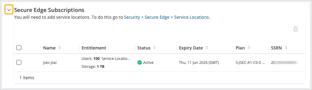
After you create your Secure Edge tenant in the SD-Cloud portal, access the portal and check your subscriptions.
To access Juniper Security Director Cloud and check active subscriptions:
-
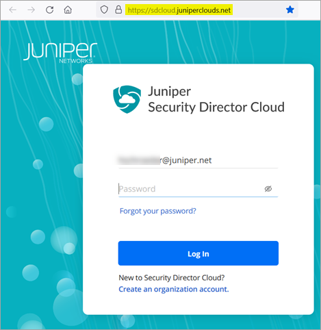
Open the URL to the Juniper Security Director Cloud.
Enter your e-mail address and password to log into the portal.
-
Select Admin >
Subscriptions to access the Security Director
Cloud subscriptions page.
Configure Service Locations
After confirming that your license for Juniper Security Director Cloud is active, you configure a service location. This task is the first step in setting up a Secure Edge connector for WAN Edge devices.
A service location in Juniper Security Director Cloud is also known as POP (point of presence) and represents a Juniper® Secure Edge instance in a cloud location. The service location is the connection (access) point for both on-premises and roaming users.
The public IP address you configure in the service location (unique per tenant and service location) is used to:
-
Set up an IPsec tunnel between the branch device and the Juniper Security Director Cloud.
-
Centrally distribute the traffic when the destination is on the Internet.
To configure a service location in Juniper Security Director Cloud:
-
Click the Add (+) icon to create a new service
location.
Table 2: Service Location Details Field Value Name Enter a descriptive name. Location 1 Select the location (POP) for the Secure Edge. The geographic region this location belongs to will be automatically selected as the region that the POP belongs to. Location 2 Select the second location (POP) for the Secure Edge. The geographic region this location belongs to is automatically selected. Subscriptions Click + to add new subscriptions, or select from your existing subscriptions. Total users Enter the total possible number of users this service location may need to serve. This is automatically set based on the subscription you chose. 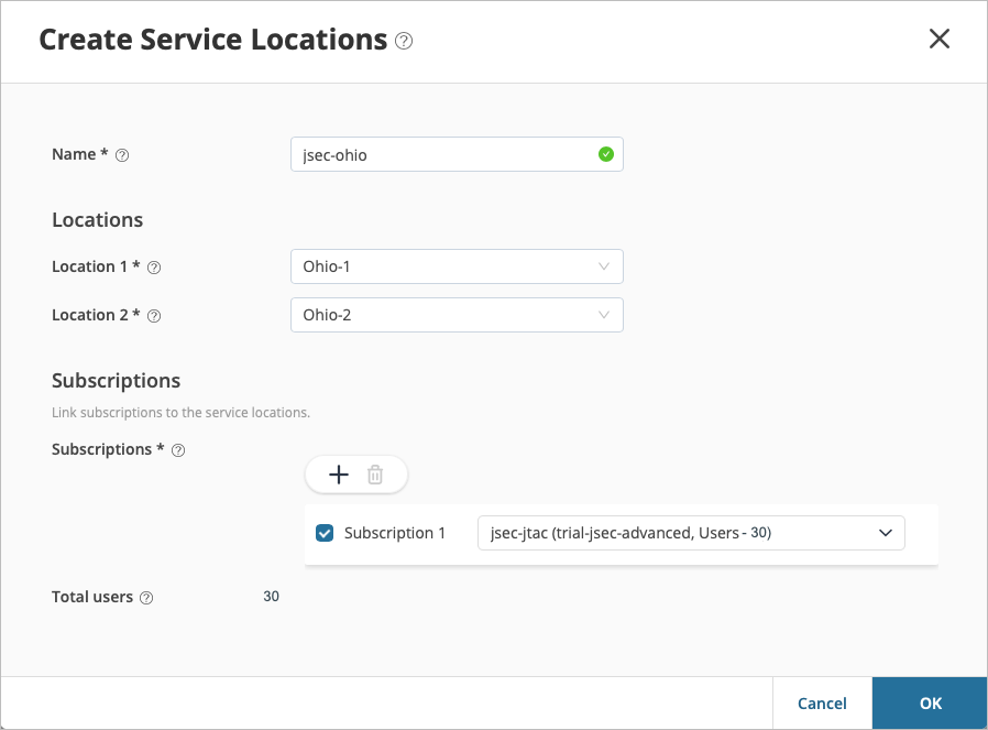
-
Click OK.
The Security Director Cloud creates a service location and lists it on the Service Locations page.
The status of the service location displays as In Progress until the Secure Edge instance is fully deployed. This can take a few moments to complete.
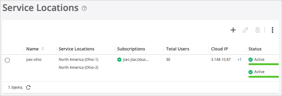
When you create a service location, it is unique per customer. Instances are not shared with other tenants.
Generate Device Certificates in Juniper Security Director Cloud
Now that you have configured service locations in Juniper Security Director Cloud, you can optionally generate device certificates for SSL decryption.
If you choose to use a Transport Layer Security/Secure Sockets Layer (TLS/SSL) certificate to establish secure communications between the clients and Juniper Secure Edge. All the client browsers on your network must trust the certificates signed by the WAN Edge devices to use an SSL proxy.
In Juniper Security Director Cloud, you have the following choices for generating certificates:
-
Create a new certificate signing request (CSR), and your own certificate authority (CA) can use the CSR to generate a new certificate.
-
Select the option to have Juniper Networks create a certificate.
This topic describes how to generate a TLS/SSL certificate. How you import and use the certificate depends on your company's client-management requirements and is beyond the scope of this topic.
To generate device certificates in Juniper Security Director Cloud:
-
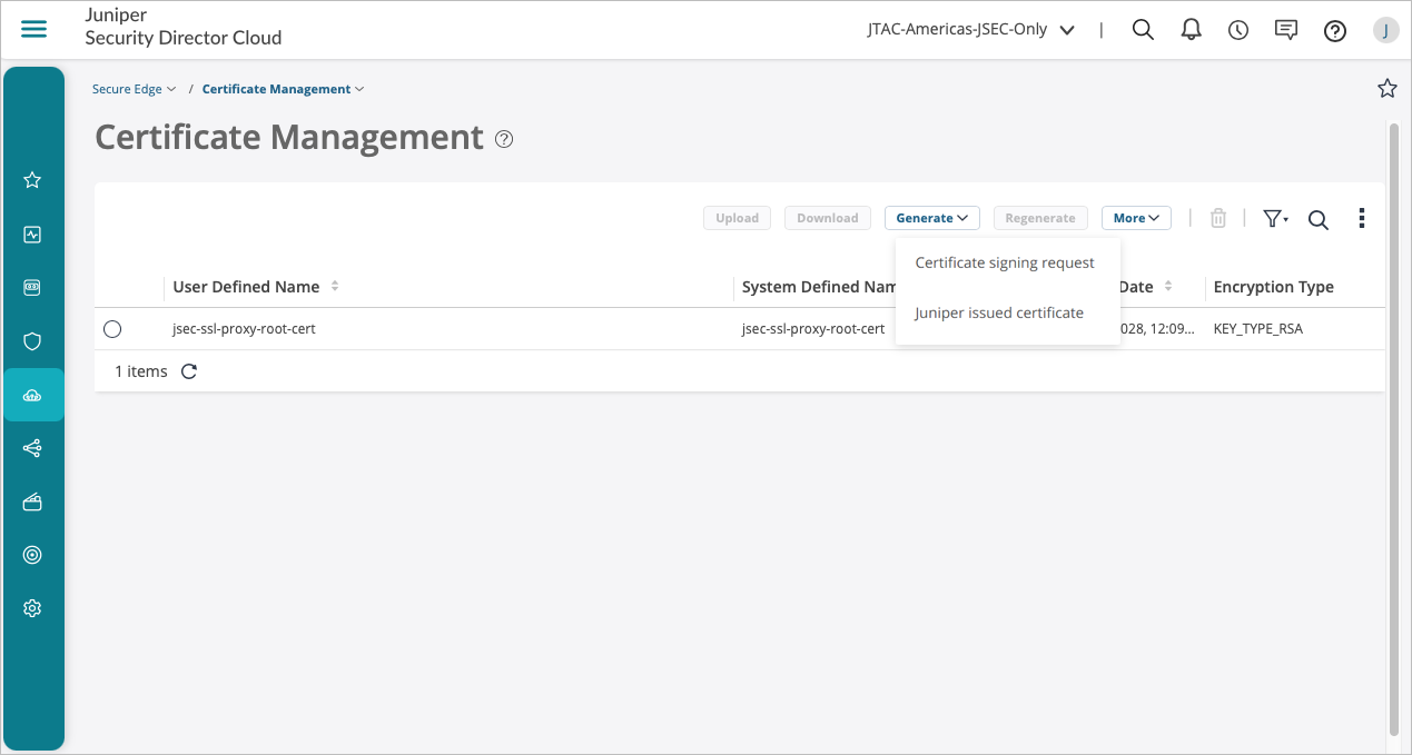
Select Secure Edge > Certificate
Management.
The Certificate Management page appears.
From the Generate drop-down list, you can generate either a new Certificate signing request (CSR) or a Juniper issued certificate.
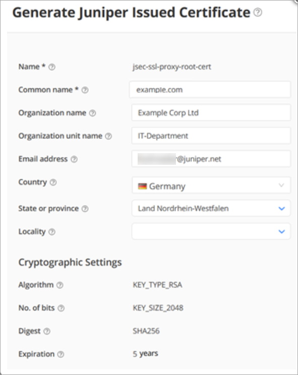
-
Enter the certificate details. In the Common name
field, use the certificate's fully qualified domain name (FQDN).
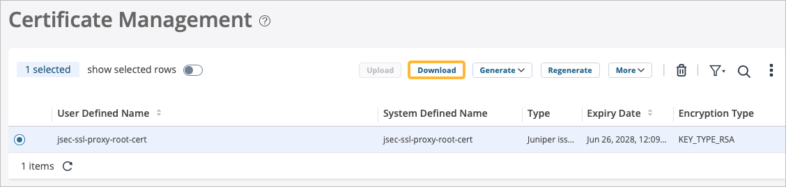
The Certificate Management page opens with a message indicating that the certificate was created successfully.
-
Select the certificate from the list, then click
Download to download the generated
certificate.
The following sample shows the downloaded certificate:
-----BEGIN CERTIFICATE-----
$ABC123#1$ABC123#1 $ABC123#1$ABC123#1 $ABC123#1$ABC123#1 $ABC123#1$ABC123#1.
.
J$ABC123#1$XYZ123#1 $ABCBVFCC123#1$ABC123#1 $XYZ123#1$GTF123#1 $XZY123#1$BVFD123#1=
$ABC123#1$XYZ123#1 $ABCBVFCC123#1$ABC123#1 $XYZ123#1$GTF123#1 $XZY123#1$BVFD123#1=
-----END CERTIFICATE-----
After you download the certificate to your system, add the certificate to client browsers.
Create an IPsec Profile in Juniper Security Director Cloud
After you generate the certificates to establish secure communications between the Juniper Secure Edge and your WAN Edge devices, you're ready to create IPsec profiles.
IPsec profiles define the parameters with which an IPsec tunnel is established when the WAN Edge devices in Mist start communicating with your Secure Edge instance.
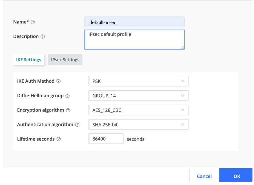
To create an IPsec profile in Juniper Security Director Cloud:
-
For the profile name, use default-ipsec. Retain all
default values for Internet Key Exchange (IKE) and IPsec; currently, they
are not configurable on the Mist portal.
You'll use this IPsec profile to create a site in the next task. On the Create Site page, if you select IPsec as the tunnel type on the Traffic Forwarding tab, you will attach the IPsec profile.
Create a Site in Juniper Secure Edge Cloud
You have now created IPsec profiles, which define the parameters for the IPsec tunnel between WAN Edge devices on your Mist cloud and your Secure Edge instance.
At this point, you need to create a site in Juniper Security Director Cloud. A site represents a location that hosts a WAN Edge device. The traffic from the WAN Edge device is forwarded to the Secure Edge instance through a secure tunnel, and then inspected and enforced by the Secure Edge cloud services.
In this configuration, you can choose to forward some or all of the Internet-bound traffic from customer sites to the Juniper Secure Edge cloud through generic routing encapsulation (GRE) or IPsec tunnels from the WAN Edge devices at the site.
Overlapping branch addresses are not supported to the same POP within the Secure Edge when using a stateful firewall at branch locations. Any reverse path traffic to these overlapping IPs will be routed using equal-cost multipath (ECMP) across all connections. Traffic is routed using ECMP rather than per-session routing to the interface from which the traffic originated. Consider reverse path traffic via ECMP when configuring the protected networks for a site.
To create a site in Juniper Security Director Cloud:
-
Enter the settings:
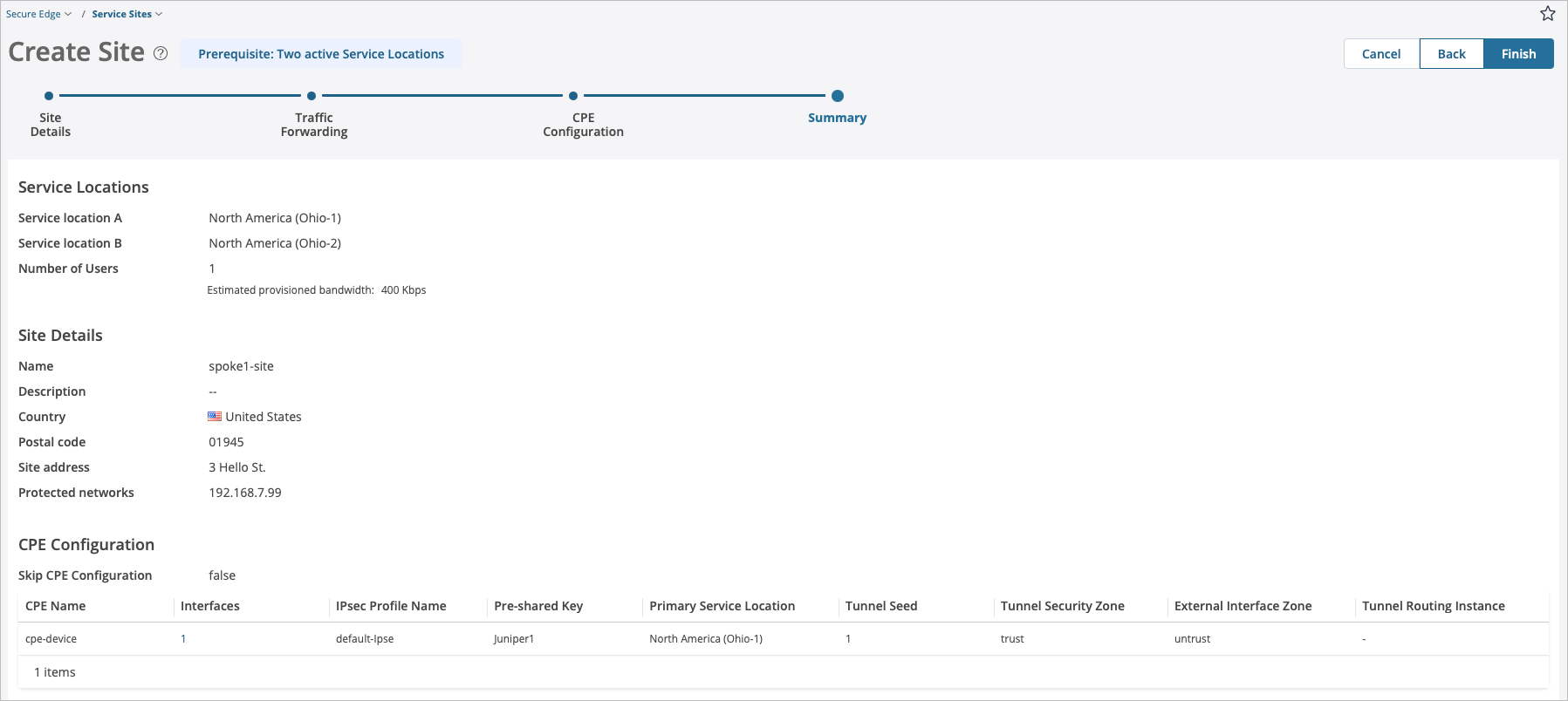
Table 3: Create Site - Service Locations Details Field Value Service location A Select the primary location that you want your on-premises sites to connect to. This is one of the locations you set up previously in Configure Service Locations. Service location B Select the secondary location that you want your on-premises sites to connect to. This is one of the locations you set up previously. Number of Users Enter the number of users who can use the network at the site. Table 4: Create Site - Site Details Field Value Name Enter a unique site name. Description Enter a unique site description. Country Select the corresponding country from the list where the site is located. Postal code (Optional) Enter the zip code where the customer branch is located. Site address (Optional) Enter the location (street address) of the site. Protected networks Click the Add (+) icon to add the private IP address range of the interface to be used for traffic flow through the tunnel (Example: 10.99.99.0/24, a LAN network IP address). 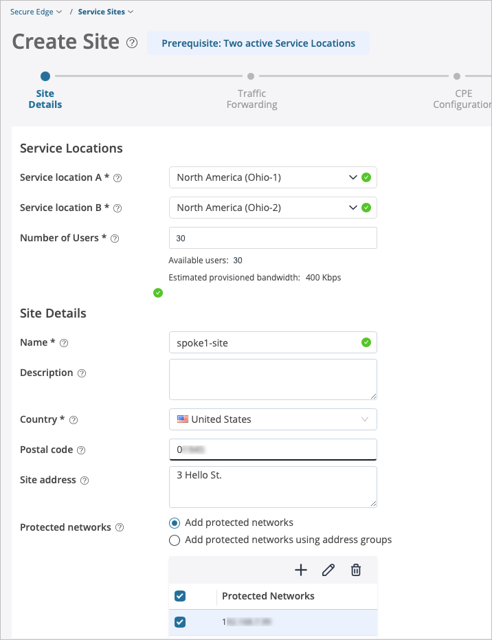
-
On the Traffic Forwarding page, enter the settings. Then, click the
checkmark.
Table 5: Interface Details for Traffic Forwarding Policy Field Value CPE Name Enter a descriptive name, such as the name of your CPE device. Interface Name Select the name of the interface. Tunnel type IPsec IP Address Type Select Dynamic IP address or Static IP address. IKE ID site1@example.com (resembles an email address and must be a unique value for each site). External Interface Enter the external interface name. An external interface connects your device to the internet/network. ge-0/0/0.0 is the default value. 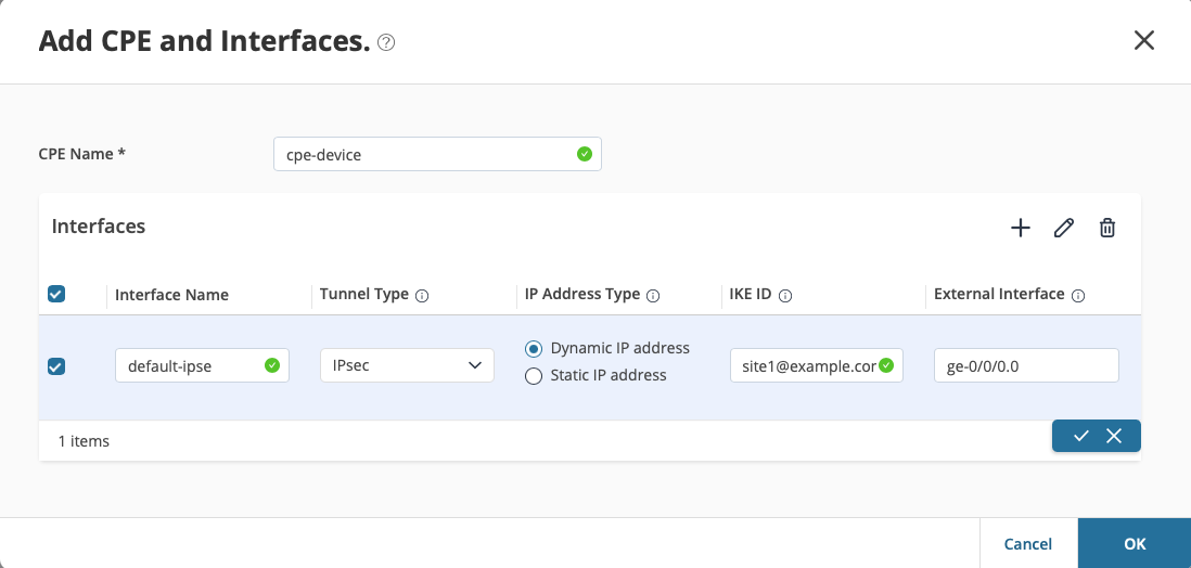
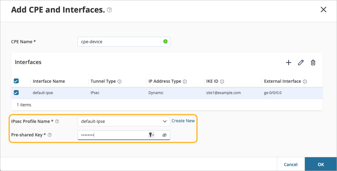
-
Select the IPsec Profile Name and enter the Pre-shared key to authenticate
the remote access user. Then, click OK.
Table 6: Additional Details for Traffic Forwarding Policy Field Value IPsec Profile Name default-ipsec If you do not have a pre-configured IPsec profile, click Create New to create an IPsec profile.
Pre-shared Key Define a unique PSK for each site. Example: Juniper!1
-
On the CPE Configuration page, select the CPE you
created in the previous step, then click the pencil in the top right.
Remember, the CPE device is a non-Juniper
device.
Table 7: CPE Configuration for Traffic Forwarding Policy Field Value CPE Name This defaults in based on what you configured previously. Interfaces This defaults in based on what you configured previously. IPsec Profile Name This defaults in based on what you configured previously. Pre-shared Key This defaults in based on what you configured previously.
Primary Service Location Select the service location from the list that primarily processes the traffic sent from the site CPE device to the Juniper Secure Edge. Tunnel Seed Enter a tunnel seed number between 1-1000. This number determines the Junos OS CLI tunnel interface identifiers. The default is 1. Tunnel Security Zone Enter the tunnel zone type of trust or untrust. Trust is the default. External Interface Zone Enter the zone type for the external interface of trust or untrust. Untrust is the default. Tunnel Routing Instance Enter the routing instance that contains the tunnel destination address. If your configuration does not have a routing instance, leave this field blank. 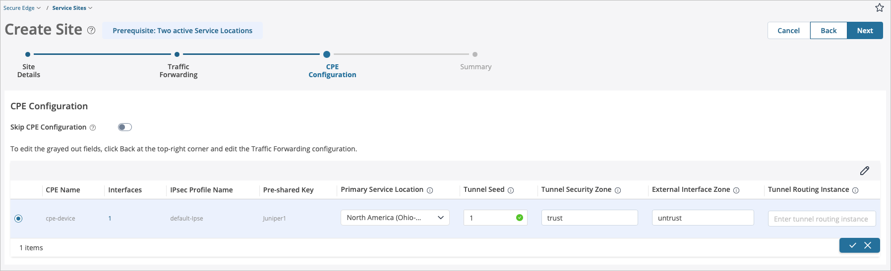
-
On the Summary page, review the configuration.
Deploy a Secure Edge Policy in Juniper Security Director Cloud
Now that you have created sites in Juniper Security Director Cloud, its time to deploy one or more Juniper® Secure Edge policies.
Secure Edge policies specify how the network routes traffic. By default, when you create a new tenant, the Security Director Cloud creates a Secure Edge policy rule set with predefined rules in it.
Even if you do not change the default rule set, you must use the Deploy option to load the rules in your service locations.
To deploy a Secure Edge policy in Juniper Security Director Cloud:
-
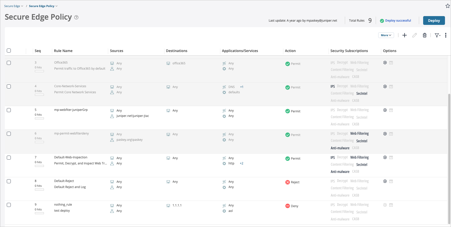
In the Juniper Security Director Cloud portal, click Secure
Edge > Secure Edge Policy.
The Secure Edge Policy page appears and contains default rules. You modify the default security policy set for better debugging. The default rule set does not allow ICMP pings to the Internet, preventing you from pinging through the cloud.
-
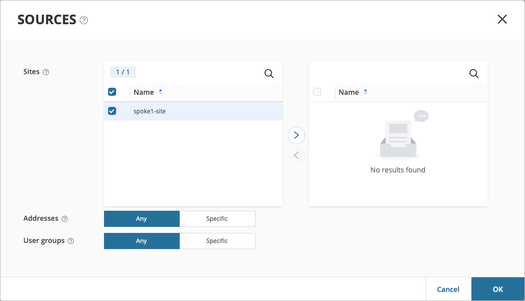
Click Add (+) to add sources.
Under Sources, use the following default values:
-
Addresses—Any
-
User Groups—Any
-
-
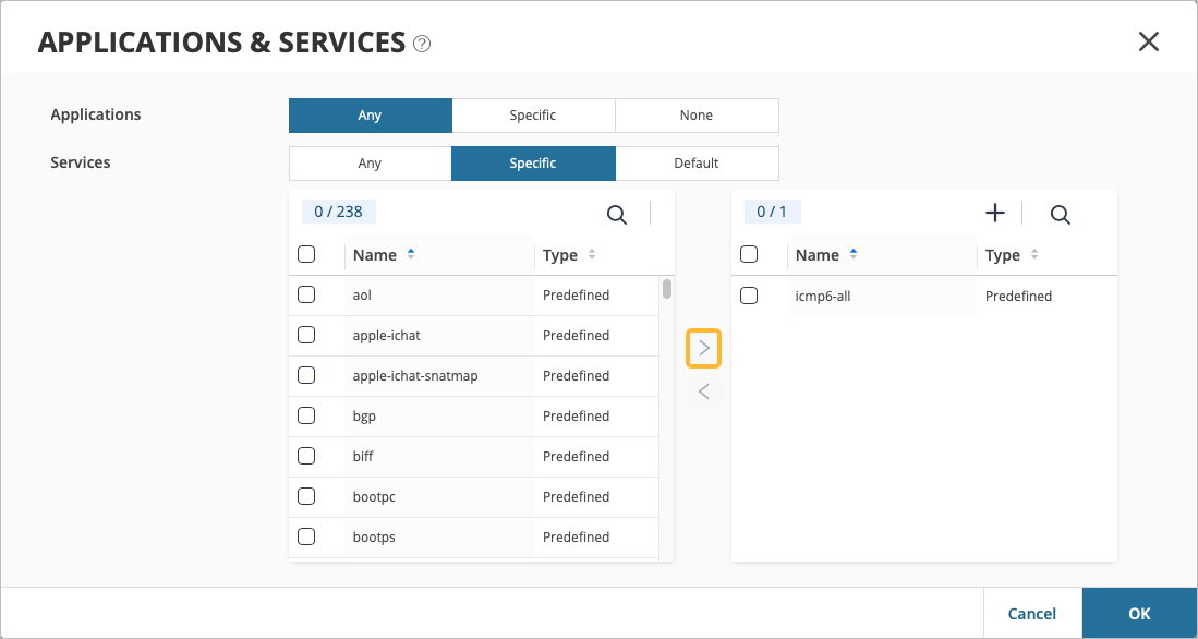
Under Applications/Services, configure the following
values:
-
Applications—Any
-
Services—Specific (via search)
-
Specific Service—icmp-all
Using the Right Arrow (>), move specific service=icmp-all to the right pane to activate it, then click OK.
-
Gather IPsec Tunnel Configuration Parameters to Apply in Juniper Security Director Cloud
In the previous tasks, you completed several actions to set up IPsec tunnels in Juniper Secure Edge and have deployed the Secure Edge policy in Juniper Security Director Cloud. The final step in Security Director Cloud is to collect configuration data for each site. In this step, you'll note down the details of the sites you created.
An automated configuration push option to synchronize between Juniper Security Director Cloud and Mist cloud is not available.
To get IPsec tunnel configuration parameters to apply in Juniper Security Director Cloud:
Create Secure Edge Connectors in the Juniper Mist Portal
You are about halfway to your ultimate goal of setting up a Secure Edge connector for your WAN Edge devices deployed in Juniper Mist™.
You create Secure Edge Connectors in the Mist portal. This task completes the tunnel configuration on the Mist cloud side to establish an IPsec tunnel between WAN Edge devices managed by Mist and Security Director Cloud. Before you create the connectors, ensure that your site has a deployed WAN Edge device.
To create Secure Edge connectors in the Mist portal:
-
From the left menu, click WAN Edges >
WAN Edges.
The WAN Edges page displays site details.
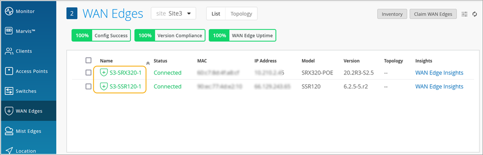
-
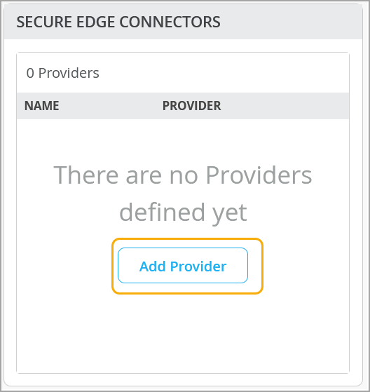
Click the device and scroll down to Secure Edge Connectors.
-
Enter Secure Edge connector details. Remember, these are same the details
you gathered in Gather IPsec Tunnel Configuration Parameters to Apply in Juniper Security Director Cloud
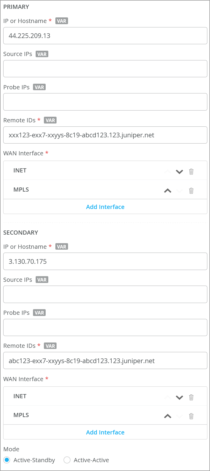
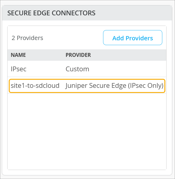
Table 12: Secure Edge Connector Details (Sample) Field Value Name site1-to-sdcloud Provider Juniper Secure Edge Local ID site1@example.com Pre-Shared Key Juniper!1 (example) Primary IP or Hostname This is the IP address from the Juniper Security Director Cloud tunnel configuration. Probe IPs You do not need to enter the probe IP values. IPsec tunnels do not need additional monitoring like GRE needs. Remote ID This is the remote ID from the Juniper Security Director Cloud tunnel configuration (Example: <UUID>.jsec-gen.juniper.net). WAN Interface -
WAN0=INET
-
WAN1=MPLS
Secondary IP or Hostname <IP address> from (From Juniper Security Director Cloud tunnel configuration) Probe IPs You do not need to enter the probe IP values. IPsec tunnels do not need additional monitoring like GRE needs. Remote ID <UUID>.jsec-gen.juniper.net (from Juniper Security Director Cloud tunnel configuration) WAN Interface -
WAN0=INET
-
WAN1=MPLS
Mode Active-standby 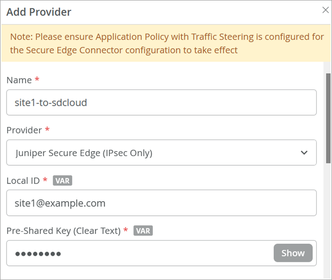
 Note:
Note:Do not enable ICMP Probe IPs for Session Smart Router-based Secure Edge configuration. ICMP probes will be sourced from a nonroutable IP address toward the Secure Edge and dropped due to policy. In addition, if the source addresses are overlapping at all branches, routing to more than one branch with a probe IP address is not supported.
-
-
Verify that the Mist portal displays the Secure Edge connector you just
configured.
Configure Traffic Steering
Configure traffic steering rules to define the paths that application traffic can take to reach its destination. You will apply this traffic steering rule to the application policy you create in the next step. See Traffic Steering Rules.
-
Add a new traffic-steering path on the WAN Edge template or WAN Edge
device.
Table 13: Traffic-Steering Path Configuration (Sample) Fields Value Name Cloud Strategy Ordered Paths Add Paths Type Secure Edge Connector Provider Juniper Secure Edge (IPsec Only) Name site1-to-sdcloud 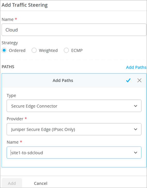
Modify an Application Policy
The next step is to modify application policies on the branch device. For example, you can allow traffic from a spoke device to a hub device. You can also allow traffic from spoke to spoke in the VPN tunnel. Then you can send traffic from spokes to the Internet through Juniper Security Director Cloud, rather than sending traffic from spokes to a hub for central breakout.
-
Add the traffic steering policy you just created. In this example, the
Traffic Steering was changed to
Cloud in the last rule.
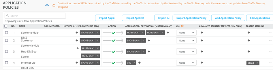 Note:
Note:If you are creating application policies from the WAN Edge device page, you may need to select the Override Template Settings option as per requirement.
Verify the IPsec Tunnel from Mist to Juniper Secure Edge (Manual)
Follow these steps to confirm that traffic is being routed from the Mist Cloud to the Juniper Secure Edge (Juniper Security Director Cloud) through the tunnel you created via the Secure Edge Connector.
- Verify the IPsec Tunnel via CLI
- Verify the Tunnel in the Mist Portal
- Check the New Traffic Flow Using a VM Desktop
Verify the IPsec Tunnel via CLI
(Optional) Depending on your environment, you can see the communication of the IPsec tunnel towards Juniper Security Director Cloud in Command Line Interface (CLI).
user@host:~# tcpdump -eni fabric6 port 4500
tcpdump: verbose output suppressed, use -v or -vv for full protocol decode
listening on fabric6, link-type EN10MB (Ethernet), capture size 262144 bytes
18:43:46.835469 52:54:00:f4:02:77 > 52:54:00:14:07:6c, ethertype IPv4 (0x0800), length 317: 192.168.173.191.16534 > 44.225.209.13.4500: NONESP-encap: isakmp: child_sa ikev2_auth[I]
18:43:46.879282 52:54:00:f4:02:77 > 52:54:00:14:07:6c, ethertype IPv4 (0x0800), length 317: 192.168.173.191.16535 > 3.130.70.175.4500: NONESP-encap: isakmp: child_sa ikev2_auth[I]
18:43:46.884834 52:54:00:14:07:6c > 52:54:00:f4:02:77, ethertype IPv4 (0x0800), length 292: 44.225.209.13.4500 > 192.168.173.191.16534: NONESP-encap: isakmp: child_sa ikev2_auth[R]
18:43:46.974426 52:54:00:14:07:6c > 52:54:00:f4:02:77, ethertype IPv4 (0x0800), length 292: 3.130.70.175.4500 > 192.168.173.191.16535: NONESP-encap: isakmp: child_sa ikev2_auth[R]
18:43:58.001576 52:54:00:14:07:6c > 52:54:00:f4:02:77, ethertype IPv4 (0x0800), length 103: 44.225.209.13.4500 > 192.168.173.191.16534: NONESP-encap: isakmp: parent_sa inf2
18:43:58.002603 52:54:00:f4:02:77 > 52:54:00:14:07:6c, ethertype IPv4 (0x0800), length 103: 192.168.173.191.16534 > 44.225.209.13.4500: NONESP-encap: isakmp: parent_sa inf2[IR]
18:44:06.111512 52:54:00:14:07:6c > 52:54:00:f4:02:77, ethertype IPv4 (0x0800), length 103: 3.130.70.175.4500 > 192.168.173.191.16535: NONESP-encap: isakmp: parent_sa inf2
18:44:06.112368 52:54:00:f4:02:77 > 52:54:00:14:07:6c, ethertype IPv4 (0x0800), length 103: 192.168.173.191.16535 > 3.130.70.175.4500: NONESP-encap: isakmp: parent_sa inf2[IR]
18:44:06.896312 52:54:00:f4:02:77 > 52:54:00:14:07:6c, ethertype IPv4 (0x0800), length 103: 192.168.173.191.16534 > 44.225.209.13.4500: NONESP-encap: isakmp: child_sa inf2[I]
18:44:06.922069 52:54:00:14:07:6c > 52:54:00:f4:02:77, ethertype IPv4 (0x0800), length 103: 44.225.209.13.4500 > 192.168.173.191.16534: NONESP-encap: isakmp: child_sa inf2[R]
18:44:07.022463 52:54:00:f4:02:77 > 52:54:00:14:07:6c, ethertype IPv4 (0x0800), length 103: 192.168.173.191.16535 > 3.130.70.175.4500: NONESP-encap: isakmp: child_sa inf2[I]
18:44:07.022502 52:54:00:14:07:6c > 52:54:00:f4:02:77, ethertype IPv4 (0x0800), length 43: 44.225.209.13.4500 > 192.168.173.191.16534: isakmp-nat-keep-alive
18:44:07.097695 52:54:00:14:07:6c > 52:54:00:f4:02:77, ethertype IPv4 (0x0800), length 103: 3.130.70.175.4500 > 192.168.173.191.16535: NONESP-encap: isakmp: child_sa inf2[R]
18:44:07.113678 52:54:00:14:07:6c > 52:54:00:f4:02:77, ethertype IPv4 (0x0800), length 43: 3.130.70.175.4500 > 192.168.173.191.16535: isakmp-nat-keep-alive
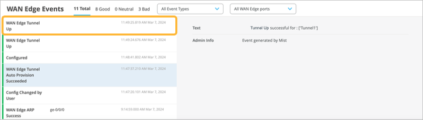
Verify the Tunnel in the Mist Portal
You can use various monitoring tools in the Mist portal to verify tunnel details.
Verify the established tunnel details by selecting WAN Edges >WAN Edges from the left menu, then click the WAN Edge device. Finally, click WAN Edge Insights. Look to see that the WAN Edge Tunnel Up event appears under WAN Edge Events.
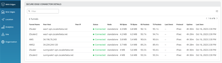
View the tunnel status and other details by navigating to WAN Edges> WAN Edges. Select the WAN Edge device, then scroll down to the Secure Edge Connector Details section.
View the tunnel statistics by navigating to WAN Edges> WAN Edges > WAN Edge name > WAN Edge Insights > Probe Stats. To view an example of this, see Tunnel Statistics
Check the New Traffic Flow Using a VM Desktop
-
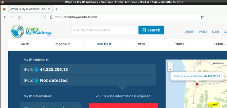
Open a browser on a VM desktop and navigate to https://whatismyipaddress.com/
to view details about the source IP address used to route the Juniper Mist
network traffic from a service location towards the Internet.
This example shows traffic from a primary service location.
This example shows traffic from a secondary service location.
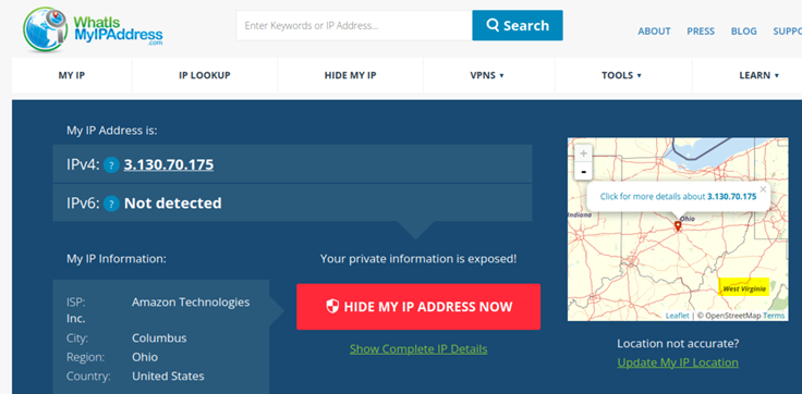
One of the two IP addresses of the service location is a public IP address and serves two purposes:
-
Terminates the IPsec tunnel
-
Routes traffic from branch devices to the Internet through Juniper Security Director Cloud
You can view this same public IP address in the packet captures showing established tunnel to the service location using Juniper Security Director Cloud.
Remember that a service location in Juniper Security Director Cloud is also known as POP and represents a Juniper® Secure Edge instance in a cloud location. The service location is the connection (access) point for both on-premises and roaming users.
-