Appendix: Topology Optimizations, Enhancements, and Extensions Valid for All Topologies
The test cases for this JVD, described in this appendix, are optional extensions to the five validated topologies. While they are not required to establish a basic VPN between branch spokes and hubs, they serve as supplemental optimizations commonly implemented in practice. Review these cases and apply them as needed based on your specific use case.
Changing the Hub Used for Central Breakout When Traffic Destination Is “Any”
When we created the WAN edge spoke template for the first lab above Create the WAN Edge Template for Spokes we defined a weighted VPN traffic steering policy that looked like the figure below:
.png)
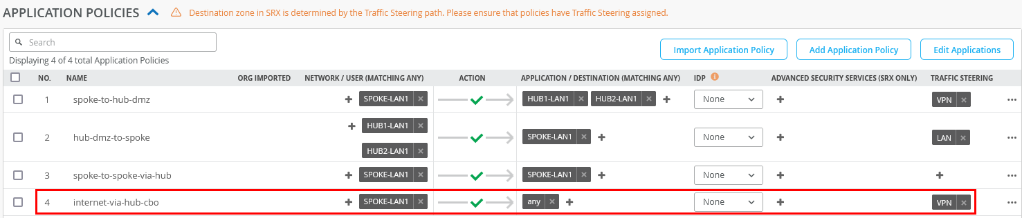
Next, we applied Rule 4 from the application policies to steer all traffic not destined for the VPN toward the two hubs for centralized Internet breakout, using “any” as the traffic destination:
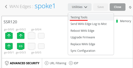
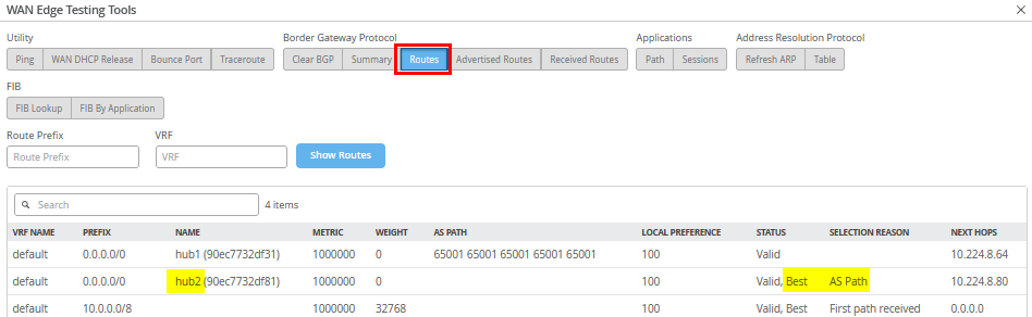
When you go to an individual spoke device under the Testing Tools dropdown:
Upon inspecting the BGP routes, you'll notice that two default routes are received—one from each hub—but currently, only the route from Hub1 is being used:
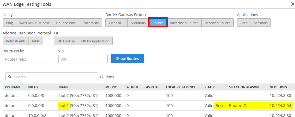
Why this route is selected is also explained because Hub1 in our
case has the neighbor IP 10.224.8.64 which is lower
than 10.224.8.80 from hub2. This is a normal process
for BGP when there is a tie for the same IP prefix obtained. As a
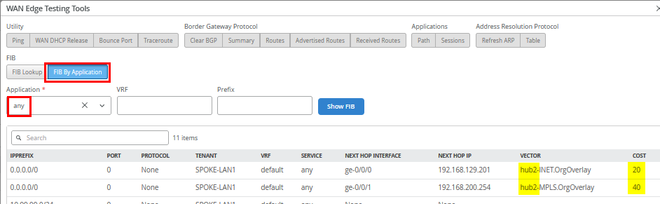
consequence, review the resulting forwarding table (FIB) via
FIB By Application selecting “any” as
Application.
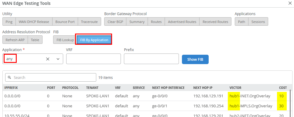
Currently, only two routes are installed—those received
from the hub selected as the default based on the lowest router ID.
The routes from Hub2 will only be used if the primary hub becomes
unavailable. This behavior is intentional, as we want to avoid
frequent switching between hubs for this 0.0.0.0/0
traffic. Keep in mind that each hub performs source NAT for
Internet-bound traffic during central breakout. If traffic were to
alternate between hubs, applications on the Internet could see the
same VPN client appearing to come from different public IP
addresses, which can cause issues.
However, the router ID is typically not configurable and is often assigned automatically during device installation. In our case, Hub1 was installed before Hub2, but that doesn’t guarantee Hub1 will have the lower router ID.
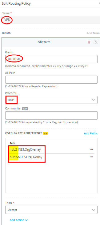
If, for any reason, you want Hub2 to be preferred over Hub1—even if Hub2 has a higher router ID—you can achieve this by modifying the spoke template. To do so, add a new routing policy with the following configuration:
- Name=
VPN - Prefix=
0.0.0.0/0 - Protocol=
BGP- Overlay Path Preference. Do not use any Hub1 path here due to router ID.
- Path1=
hub2-INET.OrgOverlay - Path2=
hub2-MPLS.OrgOverlay
- Then=
Accept
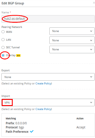
Then add a new BGP group as follows:
- Name=
hub2-as-default - Overlay=
Checked/Enabled - Export=
None - Import=
VPN
Save your template so that it gets applied to your spokes.
When you go back to the spoke and review the routes again, you will see that Hub2 now offers the best routes by BGP AS Path selection.
Upon rechecking the forwarding table (FIB), you’ll see that the change we made now selects Hub2 as the destination for this traffic—exactly the outcome we intended through our local BGP route manipulation.
Local Traffic Breakout at the Spoke
In this section, we will modify the default forwarding behavior of the VPN that was configured in the first lab Appendix: Building a base SD-WAN Topology with Three Spokes and Two Hubs. Remember, the model used routes all Internet-bound traffic through the hub, which then performs central breakout using source NAT before forwarding it to the Internet.
.png)
However, this configuration may not align with customer-specific designs or application requirements for Internet access. In some cases, it may be preferable for the spoke to handle local internet breakout through its own WAN interfaces, performing source NAT for the following reasons:
- Reduced Latency: Local breakout at the spoke typically provides a shorter and more direct path to Internet applications compared to routing through the hub for central breakout.
- Optimized VPN Resources: By offloading Internet-bound traffic locally, more bandwidth and resources are available for the VPN overlay.
- Traffic Isolation: You may not want traffic from spoke-local networks—such as an isolated Wi-Fi guest network not advertised in the VPN overlay—to traverse the VPN. This is similar to the guest network example described in the lab Appendix: Building an Extended Full Stack Topology with Juniper EX Switch Virtual Chassis and SSR HA Cluster example above.
Using the lab scenario Appendix: Building a base SD-WAN Topology with Three Spokes and Two Hubs as a foundation, this section demonstrates how to configure:
- Local breakout at the spoke via WAN interfaces with source NAT.
- Local breakout for all Internet traffic instead of routing it through the hub for central breakout.
- Local breakout for specific applications identified by DNS, while keeping central breakout as the default for all other traffic.
Local breakout for an isolated LAN network can be reviewed when following the instructions for lab Appendix: Building a Full Stack Topology with Juniper EX Switch and Juniper AP and lab Appendix: Building an Extended Full Stack Topology with Juniper EX Switch Virtual Chassis and SSR HA Cluster already.
The examples for local breakout can be extended by the information shared below in section Advanced Application Steering. This section is not intended to present a full list of possible configurations.
Checking the WAN Interfaces to Perform Source NAT
First, check your existing WAN interface configuration in the
spoke WAN Edge template. In our case, we have two called
INET and MPLS as shown in the figure
below:
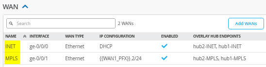
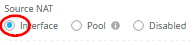
Every interface that we want to utilize for local breakout must have the following configured:
- Source NAT=
Interface
Configure an LBO Traffic Steering Policy
In our case, we want to use the Internet WAN interface as a primary interface for local breakout and the MPLS interface as a secondary interface. Hence, we configure an additional traffic steering policy in the spoke WAN Edge template:
- Name=
LBO - Strategy=
Weighted - Paths
- Type1=
WAN: INET - Cost1=
10 - Type2=
WAN: MPLS - Cost2=
20
- Type1=
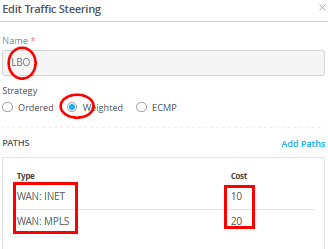
When configuring the traffic steering policy for local breakout using WAN interfaces, avoid using the ECMP option. ECMP can cause traffic to be load-balanced across multiple WAN interfaces on a per-flow basis, potentially resulting in different public IP addresses due to varying Internet paths. This behavior can lead to issues with applications that expect a consistent source IP address..
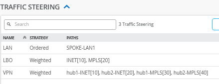
The result should look like the figure below:
Local Breakout of all Internet Traffic Instead of Central Breakout
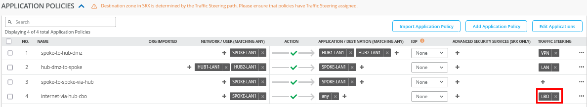
For this example, you just need to change Rule 4 from
VPN to LBO as indicated in the figure
below:
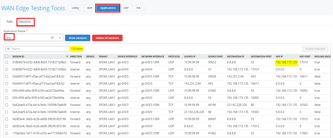
Once this configuration change is applied, generate
internet-bound traffic from clients connected to your
spokes—such as the desktop1 VM connected to Spoke1. After
initiating traffic, use the spoke’s Testing
Tools to analyze sessions under Applications ->
Session with Application Name=any, as shown
in the figure below. For a busy website like reddit.com, you'll see
a large number of captured sessions. The NAT IP allows you to infer
which interface was used for source NAT.
Local Breakout for a Custom Application Identified by DNS
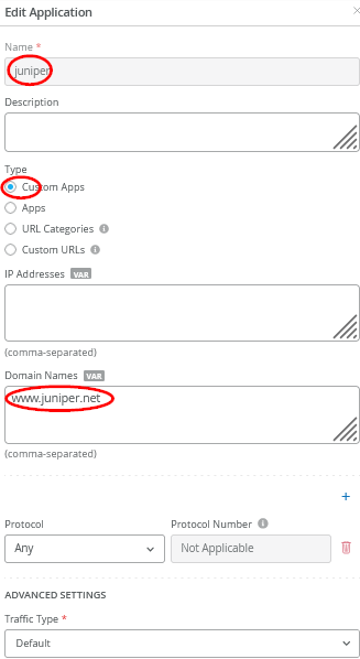
In this example, we create a new application which we will identify by DNS and then send its traffic towards the local breakout. Go to Organization -> Applications and configure the following:
- Name=
juniper - Type=
Custom Apps - Domain Names=
www.juniper.net
Then, go to your existing WAN Edge template and insert the following application policy:
- Number=
4- Name=
juniper-traffic - Network=
SPOKE-LAN1 - Action=
Pass - Application=
juniper - Traffic Steering=
LBO
- Name=
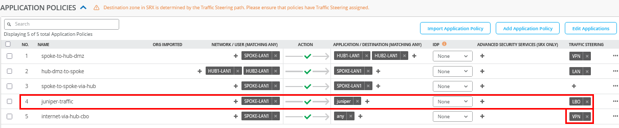
We also reverted the “any” rule to use the VPN for central breakout. Apply this change.
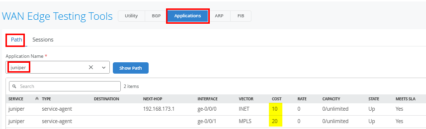
On your WAN Edge spoke, navigate to the Testing
Tools section and select Applications ->
Path with Application Name=juniper, as shown
in the figure below. This view displays the configured WAN
interfaces used for the traffic along with their associated path
costs.
Now, we need to generate traffic using this custom application. In our example, we use the desktop1 VM attached to Spoke1 and pointing a browser towards https://www.juniper.net.
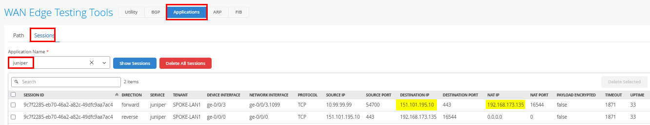
Using Testing Tools again, select
Applications -> Sessions with Application
Name=juniper as indicated in the figure below. You
should see a few sessions using this path now (most of the content
comes from CDN which we did not configure here).
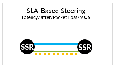
Traffic Path SLA-Based Failover
When deploying your SD-WAN VPN with multiple paths, you can leverage the SLA-based failover mechanism provided by the Session Smart Router. The router continuously monitors latency, jitter, and packet loss on each path. Administrators can define traffic SLAs using custom or pre-configured thresholds for these metrics. Based on real-time measurements, the system can detect when a path no longer meets the defined SLA. If an alternate path remains within acceptable thresholds, the traffic is automatically rerouted to maintain performance and avoid service degradation.
Except for the predefined “any” application, you can define such traffic SLAs under Advanced Settings by changing the traffic type from the default setting.
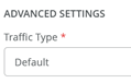
Changing the default traffic type value enables you to influence the traffic failover policy indicated in the figure below:
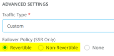
- Revertible means that the traffic after an SLA-based failover will switch back to the old path once the SLA for that path has recovered.
- Non-Revertible means that the traffic after an SLA-based failover will stay on the new path until it experiences an SLA violation, and a new failover decision needs to be made.
- None disables SLA-based failovers.
The table below outlines the predefined traffic types available for selection, or you can choose the custom option to define your own.
| Traffic Type | Traffic Class | DSCP Class | Max. Latency | Max. Jitter | Max. Loss |
|---|---|---|---|---|---|
| Custom | Default=Best Effort | Default=8 | Custom defined | Custom defined | Custom defined |
| Data Best Effort | Low | 0 | 1625 | N/A | 30 |
| Data Interactive | Medium | 18 | 600 | N/A | 30 |
| Data Mission Critical | Medium | 26 | 750 | N/A | 25 |
| Data Scavenger | Best Effort | 8 | 1625 | N/A | 30 |
| Gaming | Medium | 18 | 500 | 200 | 25 |
| Management Interactive | Medium | 16 | 650 | N/A | 25 |
| Management M2M | Medium | 16 | 1000 | N/A | N/A |
| Remote Desktop | Medium | 32 | 1300 | 500 | 25 |
| Video Streaming | Medium | 26 | 3000 | 200 | 30 |
| Video Streaming Scavenger | Best Effort | 8 | 3000 | 250 | 35 |
| VoIP Audio | High | 46 | 150 | 30 | 35 |
| VoIP Signaling | Medium | 40 | 250 | N/A | N/A |
| VoIP Video | Medium | 32 | 1500 | 250 | 35 |
Here is an example of how you can test this: Go to
Organization -> Applications and edit the
existing Application HUB1-LAN1 in the following
way:
- Traffic Type=
Custom - Failover Policy=
Revertible - Traffic Class=
Best Effort - DSCP Class=
8 - Maximum Latency=
100
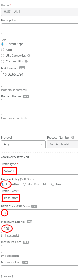
Save your configuration so that it gets applied.
We shall now continue our testing on the clients attached to the
spokes. We connect to the desktop1 VM with IP address
10.99.99.99 attached to Spoke1 and set up a continuous
ping to desktop4 VM with IP address 10.66.66.66 which is attached
to Hub1. This generates traffic utilizing the SLA.
root@desktop1:~# ping 10.66.66.66
PING 10.66.66.66 (10.66.66.66) 56(84) bytes of data.
64 bytes from 10.66.66.66: icmp_seq=1 ttl=59 time=12.7 ms
64 bytes from 10.66.66.66: icmp_seq=2 ttl=59 time=11.4 ms
64 bytes from 10.66.66.66: icmp_seq=3 ttl=59 time=11.3 ms
64 bytes from 10.66.66.66: icmp_seq=4 ttl=59 time=11.3 ms
64 bytes from 10.66.66.66: icmp_seq=5 ttl=59 time=11.2 ms
64 bytes from 10.66.66.66: icmp_seq=6 ttl=59 time=11.2 ms
64 bytes from 10.66.66.66: icmp_seq=7 ttl=59 time=11.3 ms
64 bytes from 10.66.66.66: icmp_seq=8 ttl=59 time=11.1 ms
64 bytes from 10.66.66.66: icmp_seq=9 ttl=59 time=11.3 ms
64 bytes from 10.66.66.66: icmp_seq=10 ttl=59 time=11.2 ms
64 bytes from 10.66.66.66: icmp_seq=11 ttl=59 time=11.3 ms
64 bytes from 10.66.66.66: icmp_seq=12 ttl=59 time=11.2 ms
64 bytes from 10.66.66.66: icmp_seq=13 ttl=59 time=11.2 ms
64 bytes from 10.66.66.66: icmp_seq=14 ttl=59 time=11.4 ms
64 bytes from 10.66.66.66: icmp_seq=15 ttl=59 time=11.3 ms
64 bytes from 10.66.66.66: icmp_seq=16 ttl=59 time=11.2 ms
64 bytes from 10.66.66.66: icmp_seq=17 ttl=59 time=11.1 ms
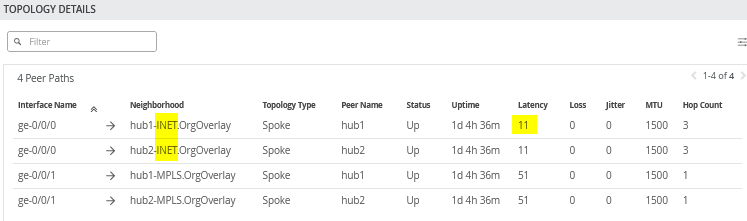
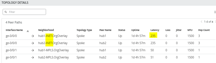
When you review the current topology report you will see the following:
- Both paths toward the hubs connected through the simulated internet have about 11ms latency. That will change in the next step.
- Both paths toward the hubs connected through MPLS will have about 51ms latency. We won’t change that throughout this exercise, hence all traffic with around 50ms will indicate that the MPLS path was used.
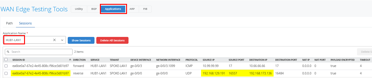
When you open Testing Tools and navigate to
Applications -> Sessions with Application
Name=HUB1-LAN1, you'll see in the return flow the
source and destination IP addresses used between the hub and spoke
over the underlay WAN for Internet traffic.
At this point, we changed the latency of the Internet path from 10 to 234ms, which you can see in the VPN overlay.
root@desktop1:~# ping 10.66.66.66
PING 10.66.66.66 (10.66.66.66) 56(84) bytes of data.
.
64 bytes from 10.66.66.66: icmp_seq=18 ttl=59 time=235 ms
64 bytes from 10.66.66.66: icmp_seq=19 ttl=59 time=235 ms
64 bytes from 10.66.66.66: icmp_seq=20 ttl=59 time=235 ms
64 bytes from 10.66.66.66: icmp_seq=21 ttl=59 time=236 ms
.
.
64 bytes from 10.66.66.66: icmp_seq=50 ttl=59 time=235 ms
64 bytes from 10.66.66.66: icmp_seq=51 ttl=59 time=235 ms
64 bytes from 10.66.66.66: icmp_seq=52 ttl=59 time=235 ms
64 bytes from 10.66.66.66: icmp_seq=53 ttl=59 time=235 ms
Again, the topology view indicates the higher latency for the Internet path due to our change.
After about 35 seconds, you see a change in latency to about 51ms which means the traffic has switched to the secondary MPLS path which has this latency in our lab.
root@desktop1:~# ping 10.66.66.66
PING 10.66.66.66 (10.66.66.66) 56(84) bytes of data.
.
64 bytes from 10.66.66.66: icmp_seq=54 ttl=61 time=52.9 ms
64 bytes from 10.66.66.66: icmp_seq=55 ttl=61 time=50.9 ms
64 bytes from 10.66.66.66: icmp_seq=56 ttl=61 time=51.1 ms
.
.
64 bytes from 10.66.66.66: icmp_seq=97 ttl=61 time=51.2 ms
64 bytes from 10.66.66.66: icmp_seq=98 ttl=61 time=51.3 ms
64 bytes from 10.66.66.66: icmp_seq=99 ttl=61 time=51.1 ms
# this is the point on time we did heal the original internet path back to 10ms
64 bytes from 10.66.66.66: icmp_seq=100 ttl=61 time=51.2 ms
64 bytes from 10.66.66.66: icmp_seq=101 ttl=61 time=51.3 ms
64 bytes from 10.66.66.66: icmp_seq=102 ttl=61 time=51.3 ms
64 bytes from 10.66.66.66: icmp_seq=103 ttl=61 time=51.3 ms
.
.
64 bytes from 10.66.66.66: icmp_seq=146 ttl=61 time=51.3 ms
64 bytes from 10.66.66.66: icmp_seq=147 ttl=61 time=51.2 ms
64 bytes from 10.66.66.66: icmp_seq=148 ttl=61 time=51.2 ms
64 bytes from 10.66.66.66: icmp_seq=149 ttl=61 time=51.2 ms
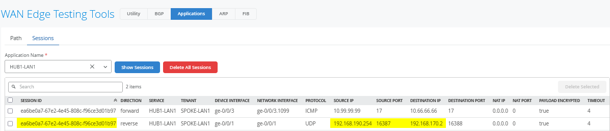
When you open Testing Tools and review
Applications -> Sessions with Application
Name=HUB1-LAN1, you'll see in the return flow the
source and destination IP addresses used between the hub and spoke
over the underlay WAN for MPLS traffic. The session ID is still the
same as well.
We recover the Internet path around ping sequence 99, and after about 50 seconds, the traffic is switched back to the original path since our failover policy is set to revertible and the latency returns back to about 11ms.
root@desktop1:~# ping 10.66.66.66
PING 10.66.66.66 (10.66.66.66) 56(84) bytes of data.
.
64 bytes from 10.66.66.66: icmp_seq=150 ttl=59 time=12.6 ms
64 bytes from 10.66.66.66: icmp_seq=151 ttl=59 time=11.2 ms
64 bytes from 10.66.66.66: icmp_seq=152 ttl=59 time=11.3 ms
64 bytes from 10.66.66.66: icmp_seq=153 ttl=59 time=11.2 ms
64 bytes from 10.66.66.66: icmp_seq=154 ttl=59 time=11.2 ms
64 bytes from 10.66.66.66: icmp_seq=155 ttl=59 time=11.2 ms
64 bytes from 10.66.66.66: icmp_seq=156 ttl=59 time=11.3 ms
Failover and revert times depend on how much the measured performance deviates from the defined SLA. The greater the margin of violation, the more aggressively the system responds. However, the system avoids reacting too aggressively to normal path fluctuations.
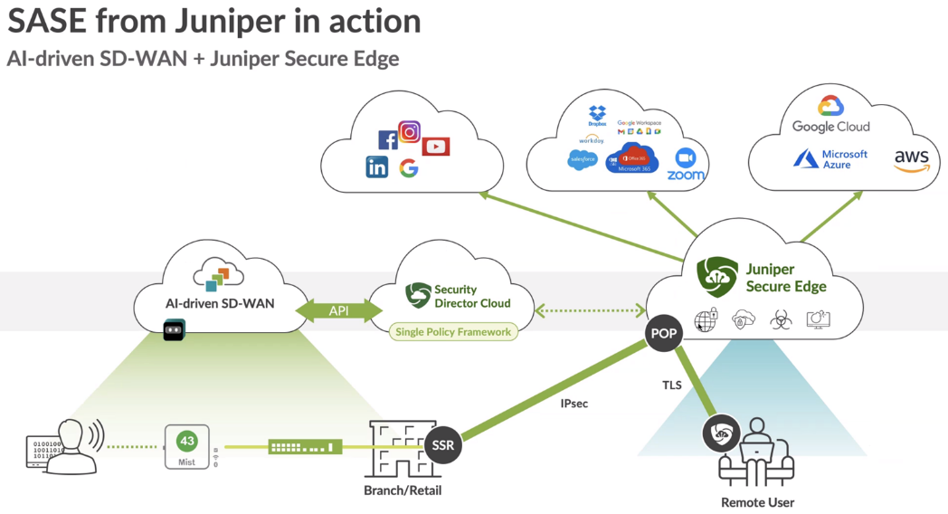
Secure Edge Connector
Juniper® Secure Edge provides full-stack security service edge (SSE) capabilities to protect access to web, SaaS, and on-premises applications. These capabilities also provide consistent threat protection, an optimized network experience, and security policies that follow users wherever they go. Secure Edge acts as an advanced cloud-based security scanner. It enables organizations to protect data and provide users with consistent, secure network access whether users are in the office, on campus, or on the move.
Juniper Mist works with Juniper Secure Edge by providing a Secure Edge Connector (SEC) that can establish a secure tunnel with the Juniper Secure Edge cloud service.

Secure Edge capabilities are all managed by Juniper Security Director Cloud, Juniper’s simple and seamless management experience delivered in a single user interface.
For more information, see Juniper Secure Edge.
Secure Edge Connector Overview
The Juniper Mist cloud works with Secure Edge to perform traffic inspection from edge devices by using the Secure Edge connector feature. This feature allows the SRX Series Firewall, deployed as a WAN edge device, to send a portion of traffic to Secure Edge for an inspection.
With this solution, you send the Internet-bound traffic from the LAN side of a spoke or hub device to Secure Edge for inspection before the traffic reaches the Internet.
To perform traffic inspection by Secure Edge:
- In Security Director Cloud, create and configure the service locations, IPsec profiles, sites, and policies for Secure Edge. These are the cloud-based resources that provide security services and connectivity for the WAN edge devices.
- In Juniper Mist cloud, create and configure the WAN edge devices, such as Session Smart Router that connect to the LAN networks. These are the devices that provide routing, switching, and SD-WAN capabilities for the branches or campuses.
- On the Juniper Mist WAN edge, create and configure the Secure Edge tunnels that connect the WAN edge devices to the service locations. These are the IPsec tunnels that provide secure and reliable transport for the traffic that needs to be inspected by Secure Edge.
- In Juniper Mist cloud, assign the Secure Edge tunnels to the sites or device profiles that correspond to the WAN edge devices. This enables the traffic steering from the LAN networks to the Secure Edge cloud-based on the defined data policies and other match criteria.
Before You Begin
- Read about the Secure Edge subscription requirements. See Juniper Secure Edge Subscriptions Overview.
- Ensure that you have completed the prerequisites to access the Juniper Security Director Cloud portal. See Prerequisites.
- Create your Secure Edge tenant. See Create Your Secure Edge Tenant.
- Assume that, in the Juniper Mist cloud, you have adopted and configured the WAN edge devices, such as Session Smart Routers that connect to the LAN networks.
Access Juniper Security Director Cloud and Check Active Subscriptions
A tenant in Secure Edge is an organization account that you create to access the Juniper Security Director Cloud portal and manage your Secure Edge services. A tenant is associated with a unique e-mail address and a subscription plan. A tenant can have multiple service locations, which are vSRX based WAN edge devices hosted in a public cloud for your organization.
A tenant can have one or more service locations, which are the connection points for end users. To create a tenant, you need to have an account on the Juniper Security Director Cloud. See Create Your Secure Edge Tenant for details.
After you create your Secure Edge tenant in the Juniper Security Director Cloud portal, access the portal and check your subscriptions.
To access Juniper Security Director Cloud and check active subscriptions:
- Open the URL to the Juniper Security Director Cloud. Enter your e-mail address and password to log in and start using the Juniper Security Director Cloud portal.
- Select the required tenant in the upper-right corner of the portal to continue.
- Select Administration -> Subscriptions to access the Juniper Security Director Cloud subscriptions page.
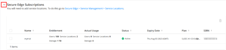
- Scroll to the Secure Edge subscriptions section to check whether you have an active subscription. For details, see About the Subscriptions Page. If you have active subscriptions, continue with the next steps.
Generate Device Certificates in Juniper Security Director Cloud
Now that you have configured service locations in Juniper Security Director Cloud, generate device certificates to secure network traffic.
You use a Transport Layer Security/Secure Sockets Layer (TLS/SSL) certificate to establish secure communications between Secure Edge and WAN edge devices. All the client browsers on your network must trust the certificates signed by Juniper Networks and the SRX Series Firewalls to use an SSL proxy.
In Juniper Security Director Cloud, you have the following choices for generating certificates:
- Create a new certificate signing request (CSR), and your own certificate authority (CA) can use the CSR to generate a new certificate.
- Select the option to have Juniper Networks create a new certificate.
This topic describes how to generate a TLS/SSL certificate. How you import and use the certificate depends on your company's client-management requirements and is beyond the scope of this topic.
To generate device certificates in Juniper Security Director Cloud:
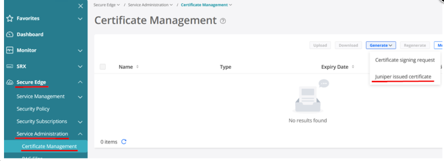
- Select Secure Edge > Service Management > Service Administration > Certificate Management.
- The Certificate Management page appears.
- From the Generate list, you can generate either a new CSR, or a Juniper-issued certificate.
- Select the relevant option:
-
If your company has its own CA and you want to generate a CSR, click Certificate signing request.
After Secure Edge generates a CSR, download the CSR and submit it to your CA to generate a new certificate. Once generated, click Upload to upload the certificate on the Certificate Management page.
-
If your company does not have its own CA, click Juniper issued certificate, and then click Generate to generate the certificate. Juniper Networks will generate and keep the certificate on the system. In this task, select Juniper issued certificate and continue with next step.
-
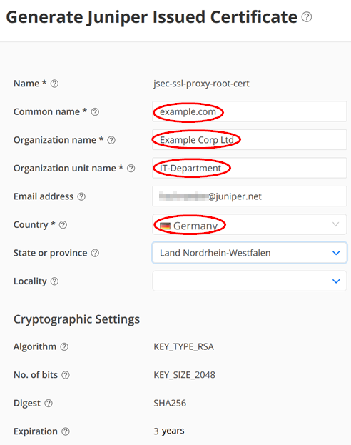
- Enter the certificate details. In the Common name field, use the certificate's fully qualified domain name (FQDN).
The Certificate Management page opens with a message indicating that the certificate is created successfully.
- Download the generated certificate.
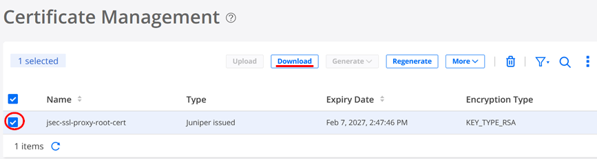
The following sample shows the downloaded certificate:
-----BEGIN CERTIFICATE-----
MIIG4jCCBMqgAwIBAgIIX3yPMZ7QT9MwDQYJKoZIhvcNAQEMBQAwgYgxCzAJBgNV
BAYTAlVTMQswCQYDVQQIEwJDQTESMBAGA1UEBxMJU3Vubnl2YWxlMR4wHAYDVQQK
.
.
JwePvBrmKGPph8k+8gL9Gqw+wnfaARP3fqp4TXUcp6twDMyP0OJR8tRm51keplVw
RAfTzy91Bhf261E62+MzKeh8J0Wi8q8Amaw6+aNVj8TcA9T/zotCI5JSkqV6+Wap
btLaf5DXSYliXWnDgt72sURF3bmUYjfDTmPgwzeMi/dal4IWUqk=
-----END CERTIFICATE-----
After you download the certificate to your system, add the certificate to client browsers.
Configure a Service Location in Juniper Security Director Cloud
After ensuring that you have an active license to Juniper Security Director Cloud, you configure a service location. This is your first main task in setting up a Secure Edge connector for Session Smart Router.
A service location in Juniper Security Director Cloud is also known as POP (point of presence) and represents a Secure Edge instance in a cloud location. The service location is the connection (access) point for both on-premises and roaming users.
Service locations are places where vSRX creates secure connections between different networks using a public cloud service. The public IP address (unique per tenant and service location) is used to:
- Set up an IPsec tunnel between the branch device and the Juniper Security Director Cloud.
- Centrally distribute the traffic when the destination is on the Internet.
To configure a service location in Juniper Security Director Cloud:
- In the Juniper Security Director Cloud menu, select Secure Edge > Service Management > Service Locations.
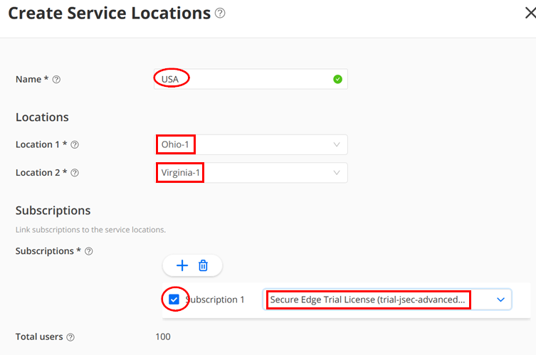
- The Service Locations page appears. Click the Add (+) icon to
create a new service location. Enter the details for the following
fields:
- Name — Give a name like “USA” below.
- Location 1 — Select the location for the Secure Edge in the region.
- Location 2 — Select the location for the Secure Edge in the region. Ensure that it is not another instance in the same region as Location 1. You usually want a backup in case the entire region fails.
- Subscriptions — Select at least one subscription which has a minimum of 100 Users.
The figure below shows examples of service locations:
- Click OK. Security Director Cloud creates a new service location and lists it on the Service Locations page.
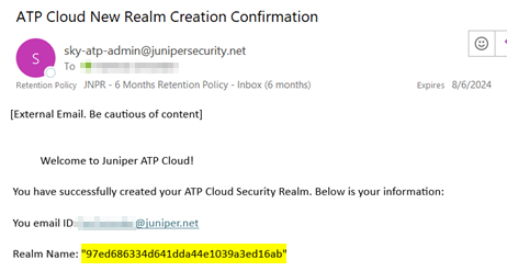
- You will receive an email confirming your action like as shown in the example below:
The status of the service location shows In Progress until the Secure Edge instance is fully deployed, as shown in the figure below:
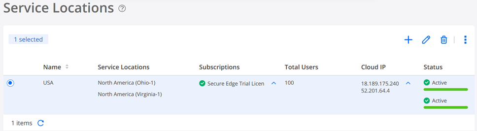
When you create a new service location, the system starts the deployment of two vSRX instances as WAN edges for your tenant system. In this deployment, vSRX instances are not shared with other tenants.
We suggest that you review the security policies https://sdcloud.juniperclouds.net/secure-edge/secure-edge-policy of your tenant. You may need to make changes to allow or deny certain Internet traffic. For basic troubleshooting, it’s recommended to allow ICMP pings to the internet. This enables you to easily verify reachability and measure path latency from a branch-connected client to the intended internet destination, when traffic is redirected through Secure Edge to the Juniper Security Director Cloud environment. An example of such a configuration is given here.
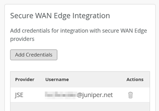
Add Juniper Security Director Cloud Account Credentials to the Mist Cloud Organization
- Go to Organization > Settings
- Click on Add Credentials
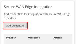
- Fill in your Credentials
- Set Provider: “JSE”
- Add your own email address on the Juniper Security Director Cloud instance
- Add your own password on the Juniper Security Director Cloud instance
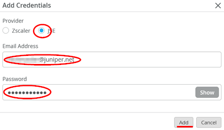
The result of should look similar to the figure below:
Create Secure Edge Connectors in the Juniper Mist Cloud Portal
You create Secure Edge connectors in the Juniper Mist cloud portal. This task completes the configuration on the Mist cloud side of the tunnels to establish an IPsec tunnel between WAN edge devices managed by Juniper Mist and Security Director Cloud. Before you create the connectors, ensure that your site has a deployed Session Smart Router.
To create Secure Edge connectors:
- In the Juniper Mist cloud portal, click WAN Edges.
The WAN Edges page displays site details.
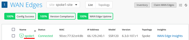
- Select a site with a deployed branch device.
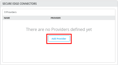
- In the Secure Edge Connectors pane, click Add Provider.
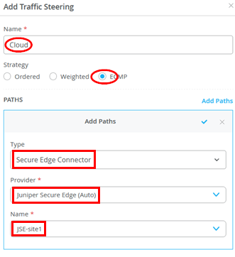
- Enter the Secure Edge connector details as shown in the figure below. Under Provider, select Juniper Secure Edge (Auto), and specify the WAN interfaces to be used for connecting to the two service locations. This setup is very similar to how two hubs are defined for standard VPN connections.
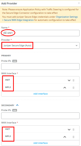
You don't need to enter the probe IP values. IPsec tunnels do not need additional monitoring like GRE needs.
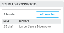
- Verify that the Juniper Mist cloud portal has added the Secure Edge connector you just configured.
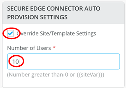
- Next, add a few user sessions to your Secure Edge Connector
- Add the traffic steering paths.
Add a new traffic steering path on the WAN edge template or WAN edge device, according to the values provided in the figure below:
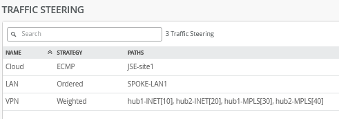
- The figure below displays the configured traffic steering paths:
Modifying the Application Policies
After you create Secure Edge connectors in the Juniper Mist portal, the next step is to modify application policies on the branch device. For example, you already allow traffic from a spoke device to a hub device and vice versa. You can also allow traffic from a spoke device to another spoke device in the VPN tunnel. After that, you can send traffic from spokes to the Internet through Juniper Security Director Cloud instead of sending traffic from spokes to a hub for central breakout.
In the example shown below, we modify, using Override Template Settings, the policy rule set so that instead of central breakout at the hub, all branch traffic towards the Internet gets shifted to the Secure Edge in the cloud.
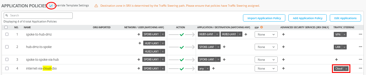
- Select the policy that you want to modify and apply the
following changes:
- Check the Override Template Settings option.
- Change the traffic steering to “Cloud” in the last
rule
internet-via-cloud-cbo.
- Save your changes.
Juniper Mist cloud builds new tunnels to Juniper Security Director Cloud.
Verify the Configuration
After you modify the application policy, you confirm that your configuration is working as expected.
With the desired configuration saved, you can verify if Juniper Mist cloud routes the Internet-bound traffic from spokes to Juniper Security Director Cloud instead of routing it to a hub for central breakout.
To verify the configuration:
- Verify the WAN Insights of the device’s established tunnels in the Juniper Mist cloud portal.
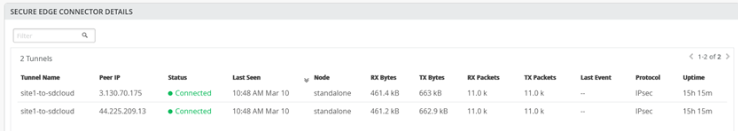
You can also check the established tunnels in the Juniper Security Director Cloud dashboard and in the service location.
- Verify the new traffic flow using a client connected to the LAN interface of the spoke. On the client, open a browser and navigate to https://whatismyipaddress.com/ to view the source IP address being used to route Juniper Mist network traffic from the service location to the internet.
The two figures below show traffic from the primary and secondary service locations:
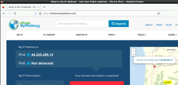
and
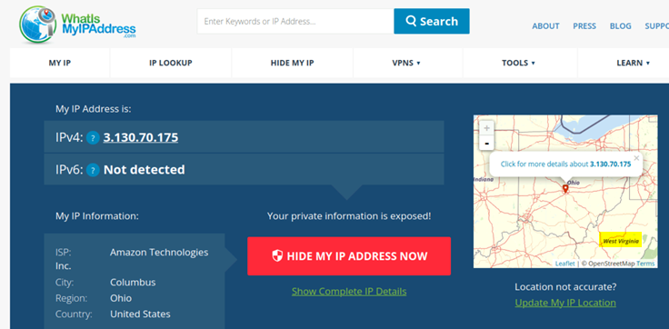
One of the two IP addresses of the service location is a public IP address and serves two purposes:
- Terminates the IPsec tunnel, hence the spoke uses it to establish the tunnel with Juniper Security Director Cloud.
- Acts as a new source IP address for traffic leaving the VPN which we can detect with the above.
Remember that a service location in Juniper Security Director Cloud is also known as a POP and represents a Secure Edge instance in a cloud location. The service location is the connection (access) point for both on-premises and roaming users.