ON THIS PAGE
Appendix: Building a base SD-WAN Topology with Three Spokes and Two Hubs
We are repeating here the topology and IP address information from above for ease of use.
This lab represents the default structure where we emulate the following:
- Installation of three spoke devices
- Installation of two hub devices
- Two underlay paths with different behavior. In the lab, the
underlay address range is
192.168.0.0/16.- MPLS path with private IP addresses.
- Internet path, subjected to NAT.
- An overlay network managed by the enterprise. It is implemented
on the LAN side of hubs and spokes. In the lab, the overlay address
range is
10.0.0.0/8.
| Device | Interface | IF-Type | Path | IP Address | Assigned | NAT |
|---|---|---|---|---|---|---|
| Spoke1 | ge-0/0/0 | WAN | INET | 192.168.173.1xx | DHCP | symmetric |
| Spoke1 | ge-0/0/1 | WAN | MPLS | 192.168.170.2 | static | none |
| Spoke1 | ge-0/0/3 | LAN | VPN | 10.99.99.1/24 | static | N/A |
| Spoke2 | ge-0/0/0 | WAN | INET | 192.168.133.1xx | DHCP | symmetric |
| Spoke2 | ge-0/0/1 | WAN | MPLS | 192.168.130.2 | static | none |
| Spoke2 | ge-0/0/3 | LAN | VPN | 10.88.88.1/24 | static | N/A |
| Spoke3 | ge-0/0/0 | WAN | INET | 192.168.153.1xx | DHCP | symmetric |
| Spoke3 | ge-0/0/1 | WAN | MPLS | 192.168.150.2 | static | none |
| Spoke3 | ge-0/0/3 | LAN | VPN | 10.77.77.1/24 | static | N/A |
| Hub1 | ge-0/0/0 | WAN | INET | 192.168.191.254 | static |
Full Cone (1:1) 192.168.129.191 |
| Hub1 | ge-0/0/1 | WAN | MPLS | 192.168.190.254 | static | none |
| Hub1 | ge-0/0/3 | LAN | VPN | 10.66.66.1/24 | static | N/A |
| Hub2 | ge-0/0/0 | WAN | INET | 192.168.201.254 | static |
Full Cone (1:1) 192.168.129.201 |
| Hub2 | ge-0/0/1 | WAN | MPLS | 192.168.200.254 | static | none |
| Hub2 | ge-0/0/3 | LAN | VPN | 10.55.55.1/24 | static | N/A |
In this lab, the emulated public IP addresses are 192.168.129.191 for Hub1 and 192.168.129.201 for Hub2. The spokes connect to these addresses.
.png)
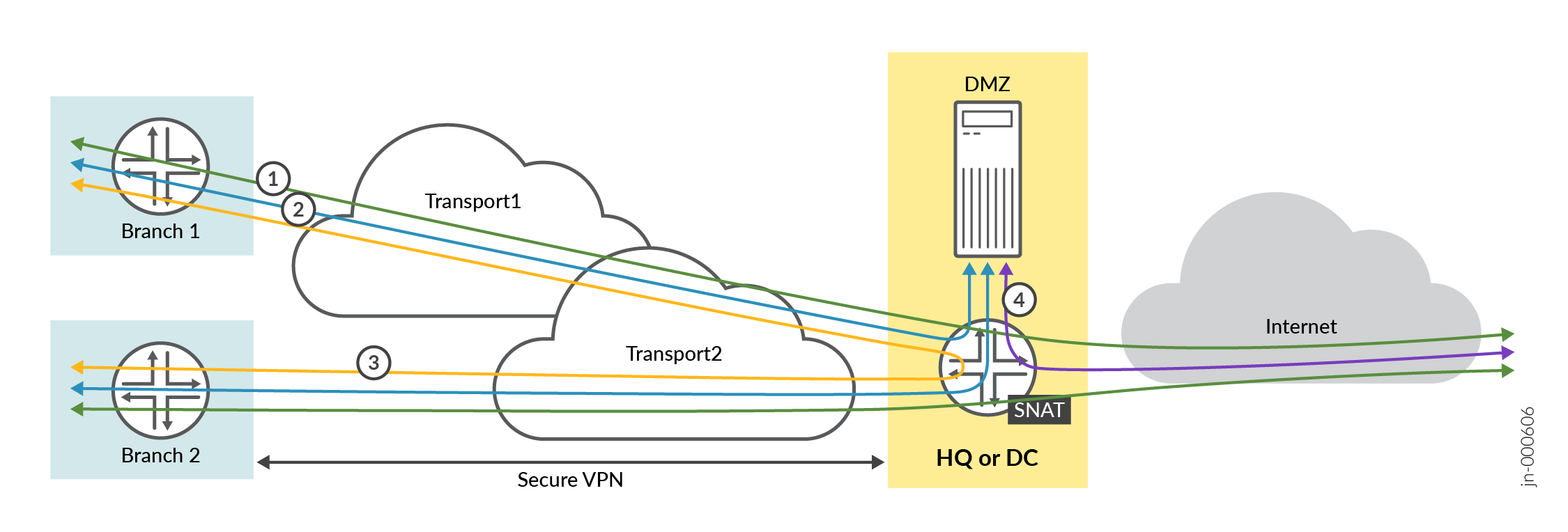
The intent of this lab is to build a VPN between the branch spoke and the hubs with the following design rules:
- All traffic from the branch spokes that is towards the Internet must go to the hub. On the hub, we enable central breakout using source NAT towards the Internet.
- Branch spokes must be able to access services and servers located at the hub in the DMZ. This must be bi-directional.
- Branch spokes can send traffic to other branch spokes but this traffic must be relayed though a hub.
- Services and servers located at the hub in the DMZ who need to send traffic toward the internet can also use the central breakout using source NAT on the hub.
Creating Sites and Site Variables
A site is a subset of your organization in the Juniper Mist cloud. You need a unique site for each physical (or logical) location in the network. Users with required privileges can configure and modify sites. The configuration changes in the sites are automatically applied to (or at least available to) all your Session Smart Routers included in the site.
Site variables provide simplicity and flexibility for deployment at a large scale.
Site variables are configured on a per-site basis. When planning a network design, you can create standard templates for specific WAN edge devices and use variables in templates or the WAN edge configuration page.
Site variables allow you to use tags (for example,
“WAN1_PUBIP”) as placeholders for actual values (for
example, 192.168.200.254), enabling context-specific
configuration. For instance, you can assign WAN1_PUBIP the value
192.168.200.254 at Site 1 and
192.168.190.254 at Site 2. These tags can then be used
in Juniper Mist cloud configurations, such as within a WAN edge
template. When the template is applied to different sites, the
Juniper Mist cloud automatically substitutes the correct IP address
for each site during configuration deployment.
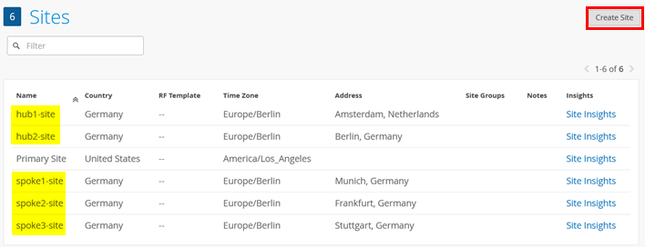
First, you need to create five sites for the spokes and hubs. Go to Organization -> Site Configuration and add five sites like the ones you see in the below example.
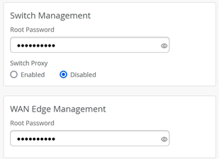
Optional: In each site, we recommend configuring the switch and WAN edge device password.
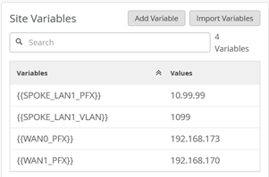
Then, you need to configure the site variables for each site that are referenced within the templates and profiles.
In our case, the site variables are configured in the following way:
- The variables such as
{{SPOKE_LAN1_PFX}},{{HUB1_LAN1_PFX}},{{HUB2_LAN1_PFX}},{{WAN0_PFX}}and{{WAN1_PFX}}represent the first three octets of an IP address or a prefix. - The variables such as
{{SPOKE_LAN1_VLAN}},{{HUB1_LAN1_VLAN}},{{HUB2_LAN1_VLAN}}contain the individual VLAN IDs. In this example, use VLAN tagging to break up the broadcast domain and separate the traffic. - The variables
{{WAN0_PUBIP}}and{{WAN1_PUBIP}}defined for the WAN interfaces of hubs use the public IP address:- The IP address of interfaces on the Internet path is in 192.168.129.x format. You can set up NAT rules for the interface.
- The IP address of interfaces on the MPLS path is in 192.168.x.254.
- Use the /24 subnet mask and do not create a variable for this field.
The full table for all sites matching our above topology is:
| Site Name | Variable | Value | Remark |
|---|---|---|---|
| spoke1-site | {{SPOKE_LAN1_PFX}} | 10.99.99 | |
| spoke1-site | {{SPOKE_LAN1_VLAN}} | 1099 | |
| spoke1-site | {{WAN0_PFX}} | 192.168.173 | Not used in template yet |
| spoke1-site | {{WAN1_PFX}} | 192.168.170 | |
| spoke2-site | {{SPOKE_LAN1_PFX}} | 10.88.88 | |
| spoke2-site | {{SPOKE_LAN1_VLAN}} | 1088 | |
| spoke2-site | {{WAN0_PFX}} | 192.168.133 | Not used in template yet |
| spoke2-site | {{WAN1_PFX}} | 192.168.130 | |
| spoke3-site | {{SPOKE_LAN1_PFX}} | 10.77.77 | |
| spoke3-site | {{SPOKE_LAN1_VLAN}} | 1077 | |
| spoke3-site | {{WAN0_PFX}} | 192.168.153 | Not used in template yet |
| spoke3-site | {{WAN1_PFX}} | 192.168.150 | |
| hub1-site | {{HUB1_LAN1_PFX}} | 10.66.66 | |
| hub1-site | {{HUB1_LAN1_VLAN}} | 1066 | |
| hub1-site | {{WAN0_PFX}} | 192.168.191 | |
| hub1-site | {{WAN0_PUBIP}} | 192.168.129.191 | |
| hub1-site | {{WAN1_PFX}} | 192.168.190 | |
| hub1-site | {{WAN1_PUBIP}} | 192.168.190.254 | Same as private interface IP |
| hub2-site | {{HUB1_LAN1_PFX}} | 10.55.55 | |
| hub2-site | {{HUB1_LAN1_VLAN}} | 1055 | |
| hub2-site | {{WAN0_PFX}} | 192.168.201 | |
| hub2-site | {{WAN0_PUBIP}} | 192.168.129.201 | |
| hub2-site | {{WAN1_PFX}} | 192.168.200 | |
| hub2-site | {{WAN1_PUBIP}} | 192.168.200.254 | Same as private interface IP |
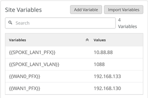
For spoke1-site, configure the following site variables:
For spoke2-site, configure the following site variables:
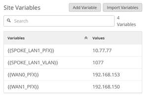
For spoke3-site configure the following site variables:
For hub1-site configure the following site variables:

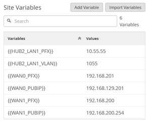
For hub2-site, configure the following site variables:
Configure Applications
Applications represent traffic destinations. On the Session Smart Router, applications create services in the background for SVR. Applications can be ports, protocols, prefixes, custom domains, or app names from the built-in AppID library.
Applications are the services or apps that your network users will connect to in a Juniper Mist WAN Assurance design. You can define these applications manually in the Juniper Mist portal. You define applications by selecting the category (such as social media) or by selecting individual applications (such as Microsoft Teams) from a list. Another option is to use the predefined list of common traffic types. You can also create a custom application to describe anything that is not otherwise available.
For users to access applications, you must first define the applications and then use application policies to permit or deny access. That is, you associate these applications with users and networks and then assign a traffic-steering policy and access rule (allow or deny).
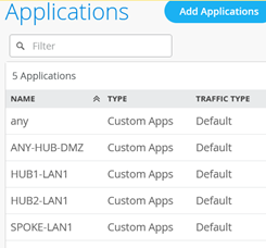
All applications we are going to use here for now are only IP address destination prefix based applications. Those are the minimum required ones for building a VPN.
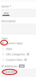
Go to Organization -> Applications. Then,
check if there is a predefined application with the name
“any” defining a custom 0.0.0.0/0 IP
address range. If that is not the case yet, define it yourself.
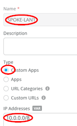
Secondly, we configure a match criterion for all IP addresses
inside the corporate VPN used. Those are typically assigned
directly or indirectly to all LAN interfaces of our hubs and
spokes. Add an application with the name set to
“SPOKE-LAN1” and under IP addresses, just configure the
single IP prefix 10.0.0.0/8. At the start, we only use
the 3 IP prefixes 10.77.77.0/24,
10.88.88.0/24, and 10.99.99.0/24 and we
could only configure those, but such a wildcard match criteria
would allow easy extensions in the future with no need to change a
ruleset to all devices in your environment.
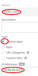
Third, we configure a match criterion for all IP addresses
attached at the LAN interface of Hub1. Add an application with the
name set to “HUB1-LAN1” and under IP addresses, just
configure the single IP prefix 10.66.66.0/24 for
now.
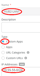
Fourth, we configure a match criterion for all IP addresses
attached at the LAN interface of Hub2. Add an application with the
name set to “HUB2-LAN1” and under IP addresses, just
configure the single IP prefix 10.55.55.0/24 for
now.
Fifth, we again configure a catch-up for all IP addresses. Add
an application with the name set to “ANY-HUB-DMZ” and
under IP addresses, just configure the single IP prefix
0.0.0.0/0. You might wonder why we do this here again
as we already define the same in the first rule with the name
“any”. This is a trick we do if you have the same
traffic forwarding desire, but the origin of the traffic comes from
different Interfaces into the system.
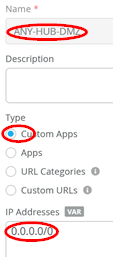
The result should look like the figure below:
Configure Networks
Networks are sources of the request in your Juniper WAN Assurance design. On the Session Smart Router, networks create tenants in the background for SVR and the Session Smart Router identifies tenants at the logical interface (network interface). LAN and WAN interface configurations identify your tenants.
Once you have created networks in the Juniper Mist portal, you can use networks across the entire organization in the portal. WAN Assurance design uses networks as the source in the application policy.
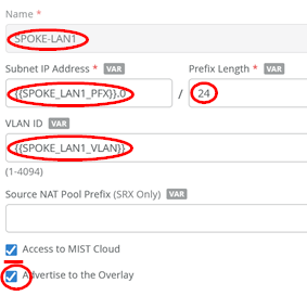
Go to Organization -> Networks. Configure the first network in the following way:
- Name=
SPOKE-LAN1 - Subnet IP Address=
{{SPOKE_LAN1_PFX}}.0this will substitute the value from the referenced site variable that contains the first three octets. - Prefix Length=
24(we only use /24 netmask in our example for ease of use). - VLAN ID=
{{SPOKE_LAN1_VLAN}}to automatically use the right tag via the site variable. - Access to Mist Cloud=
Checked/Enabled. We want possible future devices to be able to be managed by the Juniper Mist cloud and have the right policy set. - Advertised via Overlay=
Checked/Enabled
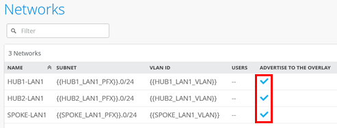
Then, configure the second network in the following way:
- Name=
HUB1-LAN1 - Subnet IP Address=
{{HUB1_LAN1_PFX}}.0this will substitute the value from the referenced site variable that contains the first three octets. - Prefix Length=
24(we only use /24 netmask in our example for ease of use). - VLAN ID=
{{HUB1_LAN1_VLAN}}to automatically use the right tag via site variable. - Access to Mist Cloud=
Checked/Enabled. We want possible future devices to be able to be managed by the Juniper Mist cloud and have the right policy set. - Advertised via Overlay=
Checked/Enabled
Then configure the third network in the following way:
- Name=
HUB2-LAN1 - Subnet IP Address=
{{HUB2_LAN1_PFX}}.0this will substitute the value from the referenced site variable that contains the first three octets. - Prefix Length=
24(we only use /24 netmask in our example for ease of use). - VLAN ID=
{{HUB2_LAN1_VLAN}}to automatically use the right tag via site variable. - Access to Mist Cloud=
Checked/Enabled. We want possible future devices to be able to be managed by the Juniper Mist cloud and have the right policy set. - Advertised via Overlay=
Checked/Enabled
The result should look like the figure below:
Create the Hub Profile for the First Hub
Each hub device in a Juniper Mist cloud topology must have its own profile. Hub profiles are a convenient way to create an overlay and assign a path for each WAN link on that overlay in Juniper Mist WAN Assurance.
The key difference between a hub profile and a WAN edge template lies in their scope and application. A hub profile is applied to a specific device at a hub site, while a WAN edge template is used across multiple spoke sites, each potentially with multiple devices, all sharing the same template. Each WAN interface on a hub creates an overlay endpoint for spoke connections, and the spoke WAN interfaces map to the appropriate hub interfaces, thereby defining the topology. Hub profiles control the creation and removal of overlay paths.
A hub profile comprises a set of attributes that associate with a particular hub device. Hub profiles include name, LAN, WAN, traffic steering, application policies, and routing options. You can assign the hub profile to a hub device and after a hub profile is loaded onto the site, the device assigned to the site picks up the attributes of that hub profile.
Go to Organization -> Hub Profiles.
Here, you have two options:
- Create the hub profile by importing an existing JSON definition. This is the best way to repeat this example without making errors or forgetting a setting.
- Create your own profile and do all the needed configuration in the Juniper Mist portal.
Should you choose to use the import option, click on Import Profile and import the below JSON as a file.
{
  "dhcpd_config": {
    "enabled": true
  },
  "ntpOverride": true,
  "dnsOverride": true,
  "service_policies": [
    {
      "name": "spoke-to-hub-dmz",
      "tenants": [
        "SPOKE-LAN1"
      ],
      "services": [
        "HUB1-LAN1"
      ],
      "action": "allow",
      "path_preference": "HUB-LANS",
      "idp": {
        "enabled": false
      }
    },
    {
      "name": "hub-dmz-to-spoke",
      "tenants": [
        "HUB1-LAN1"
      ],
      "services": [
        "SPOKE-LAN1"
      ],
      "action": "allow",
      "local_routing": true,
      "idp": {
        "enabled": false
      }
    },
    {
      "name": "spoke-to-spoke-hairpin",
      "tenants": [
        "SPOKE-LAN1"
      ],
      "services": [
        "SPOKE-LAN1"
      ],
      "action": "allow",
      "local_routing": true
    },
    {
      "tenants": [
        "HUB1-LAN1"
      ],
      "services": [
        "ANY-HUB-DMZ"
      ],
      "action": "allow",
      "path_preference": "CBO",
      "name": "hub-dmz-to-internet",
      "idp": {
        "enabled": false
      }
    },
    {
      "tenants": [
        "SPOKE-LAN1"
      ],
      "services": [
        "any"
      ],
      "action": "allow",
      "name": "spokes-traffic-cbo-on-hub",
      "path_preference": "CBO",
      "idp": {
        "enabled": false
      }
    }
  ],
  "ip_configs": {
    "HUB1-LAN1": {
      "type": "static",
      "ip": "{{HUB1_LAN1_PFX}}.1",
      "netmask": "/24"
    }
  },
  "dns_servers": [
    "8.8.8.8",
    "9.9.9.9"
  ],
  "port_config": {
    "ge-0/0/0": {
      "name": "INET",
      "usage": "wan",
      "wan_type": "broadband",
      "aggregated": false,
      "redundant": false,
      "traffic_shaping": {
        "enabled": false
      },
      "wan_ext_ip": "{{WAN0_PUBIP}}",
      "ip_config": {
        "type": "static",
        "ip": "{{WAN0_PFX}}.254",
        "netmask": "/24",
        "gateway": "{{WAN0_PFX}}.1"
      },
      "vpn_paths": {
        "hub1-INET.OrgOverlay": {
          "role": "hub"
        }
      }
    },
    "ge-0/0/1": {
      "name": "MPLS",
      "usage": "wan",
      "wan_type": "broadband",
      "aggregated": false,
      "redundant": false,
      "traffic_shaping": {
        "enabled": false
      },
      "wan_ext_ip": "{{WAN1_PUBIP}}",
      "ip_config": {
        "type": "static",
        "ip": "{{WAN1_PFX}}.254",
        "netmask": "/24",
        "gateway": "{{WAN1_PFX}}.1"
      },
      "vpn_paths": {
        "hub1-MPLS.OrgOverlay": {
          "role": "hub"
        }
      }
    },
    "ge-0/0/3": {
      "usage": "lan",
      "networks": [
        "HUB1-LAN1"
      ]
    }
  },
  "bgp_config": {},
  "routing_policies": {},
  "extra_routes": {},
  "path_preferences": {
    "HUB-LANS": {
      "strategy": "ordered",
      "paths": [
        {
          "type": "local",
          "networks": [
            "HUB1-LAN1"
          ]
        }
      ]
    },
    "CBO": {
      "strategy": "ordered",
      "paths": [
        {
          "name": "INET",
          "type": "wan"
        }
      ]
    }
  },
  "ospf_areas": {},
  "vrf_instances": {},
  "tunnel_configs": {},
  "oob_ip_config": {
    "type": "dhcp",
    "node1": {
      "type": "dhcp"
    }
  },
  "tunnel_provider_options": {
    "jse": {},
    "zscaler": {}
  },
  "ospf_config": {
    "enabled": false,
    "areas": {}
  },
  "name": "hub1",
  "type": "gateway"
}
Should you decide to configure everything manually in the Juniper Mist portal, then use the following steps:
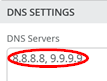
Edit the DNS Settings:
- DNS Servers=
8.8.8.8, 9.9.9.9
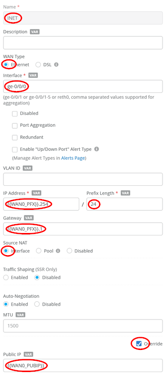
Configure a first WAN interface as follows:
- Name=
INETthis indicates which topology it’s going to use. - WAN Type=
Ethernet - Interface=
ge-0/0/0 - IP Address=
{{WAN0_PFX}}.254 - Prefix Length=
24 - Gateway=
{{WAN0_PFX}}.1 - Source NAT=
Interface - Override for Public IP=
Checked/Enabled - Public IP=
{{WAN0_PUBIP}} - The Overlay Hub Endpoint will be automatically generated and should be “hub1-INET”.
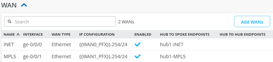
Configure a second WAN interface as follows:
- Name=
MPLSthis indicates which topology it’s going to use. - WAN Type=
Ethernet - Interface=
ge-0/0/1 - IP Address=
{{WAN1_PFX}}.254 - Prefix Length=
24 - Gateway=
{{WAN1_PFX}}.1 - Source NAT=
Interface - Override for Public IP=
Checked/Enabled - Public IP=
{{WAN1_PUBIP}} - The Overlay Hub Endpoint will be automatically generated and should be “hub1-MPLS”.
The result should look like the figure below:
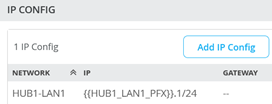
Add a LAN IP config now with the following configuration:
- Network=
HUB1-LAN1 - IP Address=
{{HUB1_LAN1_PFX}}.1 - Prefix Length=
24
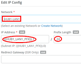
The result should look like the figure below:
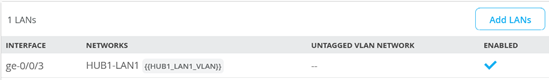
Add a LAN interface now with the following configuration:
- Interface=
ge-0/0/3 - Networks=
HUB1-LAN1 - Untagged VLAN=
None
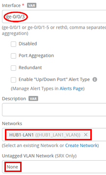
The result should look like the figure below:
Traffic steering is where you define the different paths that application traffic can take to traverse the network. The paths that you configure within traffic steering determine the destination zone. For any traffic steering policy, you need to define the paths for traffic to traverse and strategies for utilizing those paths. Strategies include:
- Ordered—Starts with a specified path and failover to backup path(s) when needed.
- Weighted—Distributes traffic across links according to a weighted bias, as determined by a cost that you input.
- Equal-cost multipath—Load balances traffic equally across multiple paths.
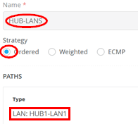
Now we need to define two traffic steering rules. The first rule has the following configuration:
- Name=
HUB-LANS - Strategy=
Ordered - Paths
- Path1 Type=
LAN: HUB1-LAN1
- Path1 Type=
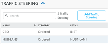
The second rule has the following configuration:
- Name=
CBO - Strategy=
Ordered - Paths
- Path1 Type=
WAN: INET
- Path1 Type=
The result should look like the figure below:
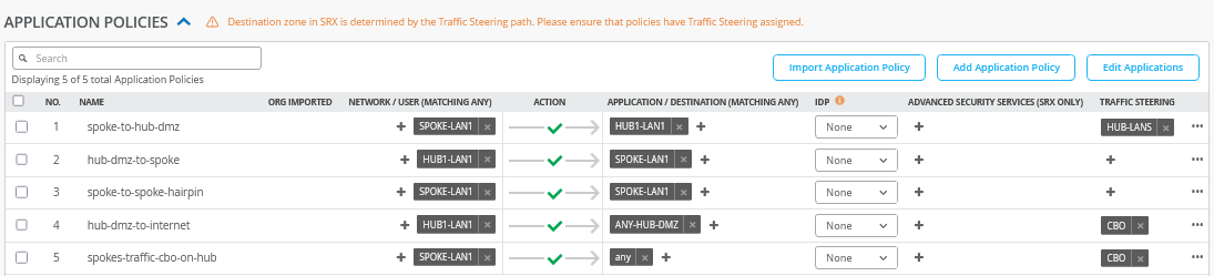
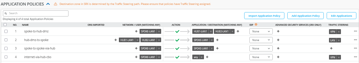
Application policies are where you define which network end users can access which applications, and according to which traffic-steering policy. The settings in Networks/Users determine the source zone. The Applications and Traffic Steering path settings determine the destination this traffic should be sent to. Additionally, you can assign a policy action—permit or deny—allowing or blocking traffic.. In our case, the following application policies are needed to implement the design rules of the VPN.
Some rules do not include a Traffic Steering policy, as it is not required for Session Smart Routers—unlike when managing a Juniper Networks® SRX Series Firewall. In these cases, the routing destination is determined by the automatically installed BGP routes within the overlay VPN.
Configure or import the following application policies:
- Number=
1- Name=
spoke-to-hub-dmz - Network=
SPOKE-LAN1 - Action=
Pass - Application=
HUB1-LAN1 - Traffic Steering=
HUB-LANS
- Name=
- Number=
2- Name=
hub-dmz-to-spoke - Network=
HUB1-LAN1 - Action=
Pass - Application=
SPOKE-LAN1 - Traffic Steering=
N/A
- Name=
- Number=
3- Name=
spoke-to-spoke-hairpin - Network=
SPOKE-LAN1 - Action=
Pass - Application=
SPOKE-LAN1 - Traffic Steering=
N/A
- Name=
- Number=
4- Name=
hub-dmz-to-internet - Network=
HUB1-LAN1 - Action=
Pass - Application=
ANY-HUB-DMZ - Traffic Steering=
CBO
- Name=
- Number=
5- Name=
spokes-traffic-cbo-on-hub - Network=
SPOKE-LAN1 - Action=
Pass - Application=
any - Traffic Steering=
CBO
- Name=
The result should look like the figure below:
The order of application policies has no impact on Session Smart Router configurations. However, as a best practice, it's recommended to place global rules at the end of the policy rule list. Assigning a traffic steering policy to each application rule is not mandatory for Session Smart Routers. These routers use iBGP-based route distribution to advertise all routes across LAN interfaces automatically. In Session Smart Router deployments, consistent network naming is required for traffic to flow between a hub and a spoke. The network name also functions as a security tenant for traffic isolation, so it must be identical on both sides to ensure proper connectivity.
Save your results.
Create the Hub Profile for the Second Hub
Go to Organization -> Hub Profiles.
Should you choose to use the import option, click on Import Profile and import the below JSON as a file.
{
  "dhcpd_config": {
    "enabled": true
  },
  "ntpOverride": true,
  "dnsOverride": true,
  "service_policies": [
    {
      "name": "spoke-to-hub-dmz",
      "tenants": [
        "SPOKE-LAN1"
      ],
      "services": [
        "HUB2-LAN1"
      ],
      "action": "allow",
      "path_preference": "HUB-LANS",
      "idp": {
        "enabled": false
      }
    },
    {
      "name": "hub-dmz-to-spoke",
      "tenants": [
        "HUB2-LAN1"
      ],
      "services": [
        "SPOKE-LAN1"
      ],
      "action": "allow",
      "local_routing": true,
      "idp": {
        "enabled": false
      }
    },
    {
      "name": "spoke-to-spoke-hairpin",
      "tenants": [
        "SPOKE-LAN1"
      ],
      "services": [
        "SPOKE-LAN1"
      ],
      "action": "allow",
      "local_routing": true
    },
    {
      "tenants": [
        "HUB2-LAN1"
      ],
      "services": [
        "ANY-HUB-DMZ"
      ],
      "action": "allow",
      "path_preference": "CBO",
      "name": "hub-dmz-to-internet",
      "idp": {
        "enabled": false
      }
    },
    {
      "tenants": [
        "SPOKE-LAN1"
      ],
      "services": [
        "any"
      ],
      "action": "allow",
      "name": "spoke-traffic-cbo-on-hub",
      "path_preference": "CBO",
      "idp": {
        "enabled": false
      }
    }
  ],
  "ip_configs": {
    "HUB2-LAN1": {
      "type": "static",
      "ip": "{{HUB2_LAN1_PFX}}.1",
      "netmask": "/24"
    }
  },
  "dns_servers": [
    "8.8.8.8",
    "9.9.9.9"
  ],
  "port_config": {
    "ge-0/0/0": {
      "name": "INET",
      "usage": "wan",
      "wan_type": "broadband",
      "aggregated": false,
      "redundant": false,
      "traffic_shaping": {
        "enabled": false
      },
      "wan_ext_ip": "{{WAN0_PUBIP}}",
      "ip_config": {
        "type": "static",
        "ip": "{{WAN0_PFX}}.254",
        "netmask": "/24",
        "gateway": "{{WAN0_PFX}}.1"
      },
      "vpn_paths": {
        "hub2-INET.OrgOverlay": {
          "role": "hub"
        }
      }
    },
    "ge-0/0/1": {
      "name": "MPLS",
      "usage": "wan",
      "wan_type": "broadband",
      "aggregated": false,
      "redundant": false,
      "traffic_shaping": {
        "enabled": false
      },
      "wan_ext_ip": "{{WAN1_PUBIP}}",
      "ip_config": {
        "type": "static",
        "ip": "{{WAN1_PFX}}.254",
        "netmask": "/24",
        "gateway": "{{WAN1_PFX}}.1"
      },
      "vpn_paths": {
        "hub2-MPLS.OrgOverlay": {
          "role": "hub"
        }
      }
    },
    "ge-0/0/3": {
      "usage": "lan",
      "aggregated": false,
      "redundant": false,
      "networks": [
        "HUB2-LAN1"
      ]
    }
  },
  "bgp_config": {},
  "routing_policies": {},
  "extra_routes": {},
  "path_preferences": {
    "HUB-LANS": {
      "strategy": "ordered",
      "paths": [
        {
          "type": "local",
          "networks": [
            "HUB2-LAN1"
          ]
        }
      ]
    },
    "CBO": {
      "strategy": "ordered",
      "paths": [
        {
          "name": "INET",
          "type": "wan"
        }
      ]
    }
  },
  "ospf_areas": {},
  "vrf_instances": {},
  "tunnel_configs": {},
  "oob_ip_config": {
    "type": "dhcp",
    "node1": {
      "type": "dhcp"
    }
  },
  "tunnel_provider_options": {
    "jse": {},
    "zscaler": {}
  },
  "ospf_config": {
    "enabled": false,
    "areas": {}
  },
  "name": "hub2",
  "type": "gateway"
}
Should you decide to configure everything manually in the Juniper Mist portal, then use the following steps. We’ve decided to clone the profile from hub1 and change the clone to hub2 for faster results. So, go to “hub1” profile and click on “clone”.

Name the clone “hub2”.
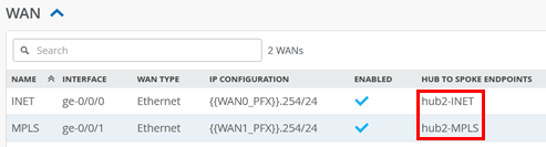
After you are on the clone profile, check that the WAN Endpoints
have changed as well to hub2-INET and
hub2-MPLS similar to the figure below:
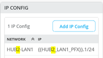
Change the IP address configuration to Hub2.
- Network=
HUB2-LAN1 - IP Address=
{{HUB2_LAN1_PFX}}
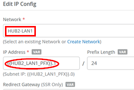
The result should look like the figure below:
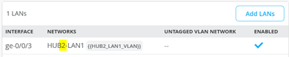
Change the LAN interface network:
- Networks=
HUB2-LAN1
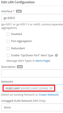
The result should look like the figure below:
Change the application policies from HUB1-LAN1 to
HUB2-LAN1 as indicated in the figure below:
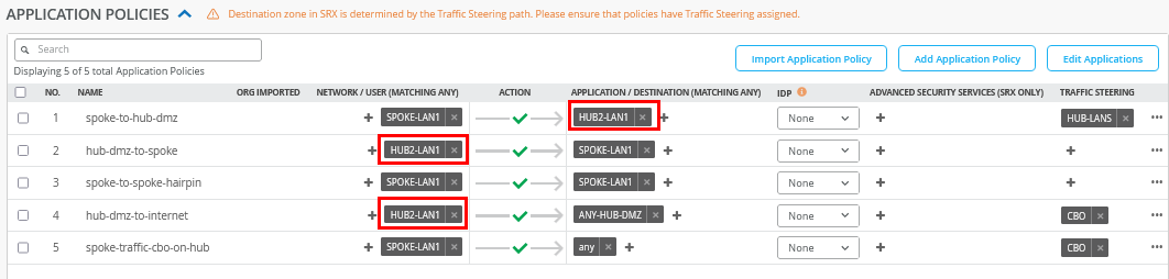
Save your results.
Create the WAN Edge Template for Spokes
Go to Organization -> WAN Edge Templates.
Here, you have two options:
- Create the template by importing an existing JSON definition. This is the best way to repeat this example without making errors or forgetting a setting.
- Create a template and make all the necessary configuration changes in the Juniper Mist portal.
Should you choose to use the import option, click on Import Profile and import the below JSON as a file.
{
  "type": "spoke",
  "dhcpd_config": {
    "enabled": true,
    "SPOKE-LAN1": {
      "type": "local",
      "ip_start": "{{SPOKE_LAN1_PFX}}.10",
      "ip_end": "{{SPOKE_LAN1_PFX}}.250",
      "gateway": "{{SPOKE_LAN1_PFX}}.1",
      "dns_servers": [
        "8.8.8.8",
        "9.9.9.9"
      ],
      "options": {},
      "lease_time": 86400,
      "fixed_bindings": {}
    }
  },
  "ntpOverride": true,
  "dnsOverride": true,
  "service_policies": [
    {
      "name": "spoke-to-hub-dmz",
      "tenants": [
        "SPOKE-LAN1"
      ],
      "services": [
        "HUB1-LAN1",
        "HUB2-LAN1"
      ],
      "action": "allow",
      "idp": {
        "enabled": false
      },
      "path_preference": "VPN"
    },
    {
      "name": "hub-dmz-to-spoke",
      "tenants": [
        "HUB1-LAN1",
        "HUB2-LAN1"
      ],
      "services": [
        "SPOKE-LAN1"
      ],
      "action": "allow",
      "path_preference": "LAN",
      "idp": {
        "enabled": false
      }
    },
    {
      "name": "spoke-to-spoke-via-hub",
      "tenants": [
        "SPOKE-LAN1"
      ],
      "services": [
        "SPOKE-LAN1"
      ],
      "action": "allow",
      "idp": {
        "enabled": false
      },
      "local_routing": true
    },
    {
      "tenants": [
        "SPOKE-LAN1"
      ],
      "services": [
        "any"
      ],
      "action": "allow",
      "name": "internet-via-hub-cbo",
      "idp": {
        "enabled": false
      },
      "path_preference": "VPN"
    }
  ],
  "ip_configs": {
    "SPOKE-LAN1": {
      "type": "static",
      "ip": "{{SPOKE_LAN1_PFX}}.1",
      "netmask": "/24"
    }
  },
  "dns_servers": [
    "8.8.8.8",
    "9.9.9.9"
  ],
  "port_config": {
    "ge-0/0/0": {
      "name": "INET",
      "usage": "wan",
      "wan_type": "broadband",
      "aggregated": false,
      "redundant": false,
      "traffic_shaping": {
        "enabled": false
      },
      "ip_config": {
        "type": "dhcp"
      },
      "vpn_paths": {
        "hub1-INET.OrgOverlay": {
          "bfd_profile": "broadband",
          "role": "spoke"
        },
        "hub2-INET.OrgOverlay": {
          "bfd_profile": "broadband",
          "role": "spoke"
        }
      }
    },
    "ge-0/0/1": {
      "name": "MPLS",
      "usage": "wan",
      "wan_type": "broadband",
      "aggregated": false,
      "redundant": false,
      "traffic_shaping": {
        "enabled": false
      },
      "ip_config": {
        "type": "static",
        "ip": "{{WAN1_PFX}}.2",
        "netmask": "/24",
        "gateway": "{{WAN1_PFX}}.1"
      },
      "vpn_paths": {
        "hub1-MPLS.OrgOverlay": {
          "bfd_profile": "broadband",
          "role": "spoke"
        },
        "hub2-MPLS.OrgOverlay": {
          "bfd_profile": "broadband",
          "role": "spoke"
        }
      }
    },
    "ge-0/0/3": {
      "usage": "lan",
      "networks": [
        "SPOKE-LAN1"
      ]
    }
  },
  "bgp_config": {},
  "routing_policies": {},
  "extra_routes": {},
  "path_preferences": {
    "VPN": {
      "strategy": "weighted",
      "paths": [
        {
          "name": "hub1-INET.OrgOverlay",
          "cost": 10,
          "type": "vpn"
        },
        {
          "name": "hub2-INET.OrgOverlay",
          "cost": 20,
          "type": "vpn"
        },
        {
          "name": "hub1-MPLS.OrgOverlay",
          "cost": 30,
          "type": "vpn"
        },
        {
          "name": "hub2-MPLS.OrgOverlay",
          "cost": 40,
          "type": "vpn"
        }
      ]
    },
    "LAN": {
      "strategy": "ordered",
      "paths": [
        {
          "type": "local",
          "networks": [
            "SPOKE-LAN1"
          ]
        }
      ]
    }
  },
  "ospf_areas": {},
  "vrf_instances": {},
  "tunnel_configs": {},
  "oob_ip_config": {
    "type": "dhcp",
    "node1": {
      "type": "dhcp"
    }
  },
  "tunnel_provider_options": {
    "jse": {},
    "zscaler": {}
  },
  "ospf_config": {
    "enabled": false,
    "areas": {}
  },
  "name": "Spokes"
}
Should you decide to configure everything manually in the Juniper Mist portal, then use the following steps.
Edit the DNS Settings
- DNS Servers=
8.8.8.8, 9.9.9.9
.png)
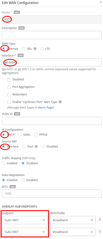
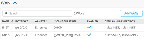
Configure a first WAN interface as follows
- Name=
INETthis indicates which topology it’s going to use. - WAN Type=
Ethernet - Interface=
ge-0/0/0 - IP Configuration=
DHCP - Source NAT=
Interface - Overlay Hub Endpoints
- Endpoint1=
hub1-INET - BFD Profile1=
Broadband - Endpoint2=
hub2-INET - BFD Profile2=
Broadband
- Endpoint1=
Configure the second WAN interface as follows:
- Name=
MPLSthis indicates which topology it’s going to use. - WAN Type=
Ethernet - Interface=
ge-0/0/1 - IP Configuration=
Static -
IP Address={{WAN1_PFX}}.2 -
Prefix Length=24 -
Gateway={{WAN1_PFX}}.1 - Source NAT=
Interface - Overlay Hub Endpoints
- Endpoint1=
hub1-MPLS - BFD Profile1=
Broadband - Endpoint2=
hub2-MPLS - BFD Profile2=
Broadband
- Endpoint1=
The result should look like the figure below:
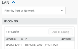
Add a LAN IP config now with the following configuration:
- Network=
SPOKE-LAN1 - IP Address=
{{SPOKE_LAN1_PFX}}.1 - Prefix Length=
24
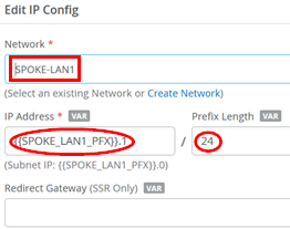
The result should look like the figure below:
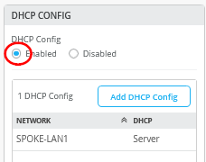
Add a DHCP server configuration like the one below:
- Network=
SPOKE-LAN1 - DHCP=
Server - IP Start=
{{SPOKE_LAN1_PFX}}.10 - IP End=
{{SPOKE_LAN1_PFX}}.250 - Gateway=
{{SPOKE_LAN1_PFX}}.1 - Maximum Lease Time=
86400 - DNS Servers=
8.8.8.8, 9.9.9.9
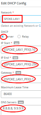
The result should look like the figure below:
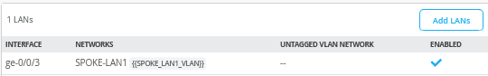
Add a LAN interface now with the following configuration:
- Interface=
ge-0/0/3 - Networks=
SPOKE1-LAN1 - Untagged VLAN=
None

The result should look like the figure below:
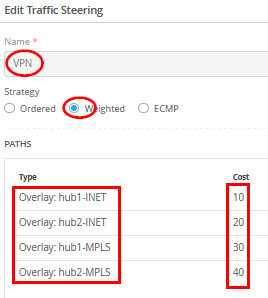
Now we need to define two traffic steering rules. The first rule has the following configuration:
- Name=
VPN - Strategy=
Weighted - Paths
- Path1 Type=
Overlay: hub1-INET- Path1 Cost=
10 - Path2 Type=
Overlay: hub2-INET - Path2 Cost=
20 - Path3 Type=
Overlay: hub1-MPLS - Path3 Cost=
30 - Path4 Type=
Overlay: hub2-MPLS - Path4 Cost=
40
- Path1 Cost=
In typical scenarios with two different hubs, assigned weights ensure that all "any" (0.0.0.0/0) traffic destined for central Internet breakout is routed through only one active hub at a time. Avoid using Equal Cost Multi-Path (ECMP) in this setup due to the source NAT being performed at each hub for Internet-bound traffic. For consistent behavior, traffic should originate from the same public IP address to maintain application session integrity. If traffic is load-balanced across hubs, applications on the internet may observe different source IPs for each flow, potentially causing issues.
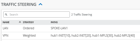
The second rule has the following configuration:
- Name=
LAN - Strategy=
Ordered - Paths
- Path1 Type=
LAN: SPOKE-LAN1
- Path1 Type=
The result should look like the figure below:
Configure or import the following Application Policies
- Number=
1- Name=
spoke-to-hub-dmz - Network=
SPOKE-LAN1 - Action=
Pass - Application=
HUB1-LAN1+HUB2-LAN1 - Traffic Steering=
VPN
- Name=
- Number=
2- Name=
hub-dmz-to-spoke - Network=
HUB1-LAN1+HUB2-LAN1 - Action=
Pass - Application=
SPOKE-LAN1 - Traffic Steering=
LAN
- Name=
- Number=
3- Name=
spoke-to-spoke-via-hub - Network=
SPOKE-LAN1 - Action=
Pass - Application=
SPOKE-LAN1 - Traffic Steering=
N/A
- Name=
- Number=
4- Name=
internet-via-hub-cbo - Network=
SPOKE-LAN1 - Action=
Pass - Application=
any - Traffic Steering=
VPN
- Name=
The result should look like the figure below:
The order of application policies has no impact on Session Smart Router configurations. However, as a best practice, it's recommended to place global rules at the end of the policy rule list. Assigning a traffic steering policy to each application rule is not mandatory for Session Smart Routers. These routers use iBGP-based route distribution to advertise all routes across LAN interfaces automatically. In Session Smart Router deployments, consistent network naming is required for traffic to flow between a hub and a spoke. The network name also functions as a security tenant for traffic isolation, so it must be identical on both sides to ensure proper connectivity.
Save your results.
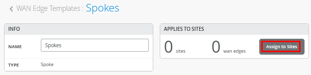
Assigning Spoke Templates to Sites
Go to Organization -> WAN Edge Templates and create a spoke template and click on Assign to Sites.
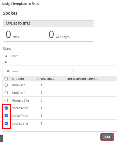
Then select only the three “spokeX-site” and “Apply”.
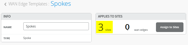
The result should indicate three sites (the WAN edges change when devices get assigned to these).
Onboard your Devices
Now it’s time to use the Claim or Adopt method to onboard the devices and see them in the organization inventory. Multiple onboarding methods are supported, but the default claim and ZTP method is described here, as it is the simplest and most straightforward approach.
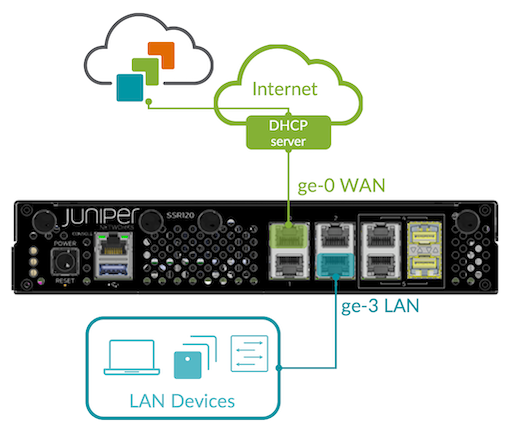
Connect Your Device to the Cloud. Your SSR
device uses port 0 (ge-0/0/0 in the Juniper Mist
portal) as a default WAN port to contact Juniper Mist for ZTP. This
interface must be able to obtain a DHCP lease to access the
Internet and communicate with the Juniper Mist cloud. A static IP
configuration can be applied later through a template or hub
profile. Connecting the LAN interface during onboarding is only
necessary when using the Adopt method.
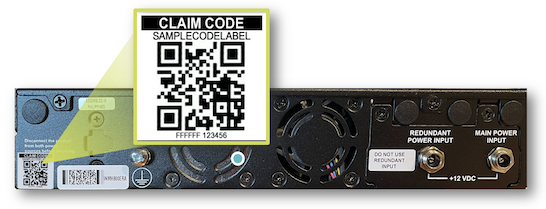
Obtain Claim code from device. On the back of the device there are two stickers with codes. It’s best that you take a photo of these for later. The left sticker has the claim code to be used on the Juniper Mist portal.
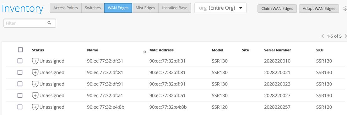
Mist Claim Code Entry. You can use the Mist mobile application to scan the QR code directly or use it on the Juniper Mist portal. Go to Organization -> Inventory, select WAN Edges and click on Claim WAN Edges as shown in the figure below:

Add the device claim code into the list of devices to claim.
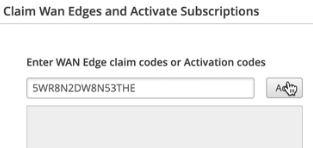
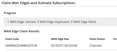
Click the Claim button to claim the device into your inventory.
The MistAI app can be downloaded from mobile app stores a.) for Apple Devices and b.) for Android Devices
In the example below, we just claimed five devices for a lab without directly assigning them to a site. This is similar to using the adopt method.
Assigning Devices to Sites
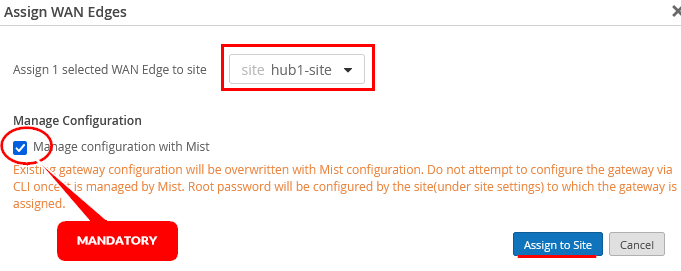
Each SSR or SRX must now be assigned one-by-one to an individual site using Assign to Site.
Select the site for each device and make sure to enable Manage configuration with Mist. The default option of not enabling device management is a better practice for SRX Firewalls.
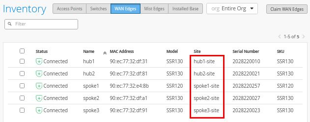
Now assign all five devices to their individual sites until you see the below:
Assign Hub Profiles to Devices
The spoke sites will automatically receive their configurations, as the templates have already been assigned. For the hub sites, however, the next step is to manually assign the appropriate hub profile.
Go to Organization -> Hub Profiles.
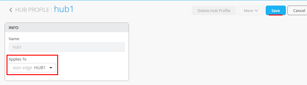
Click on the first hub profile.
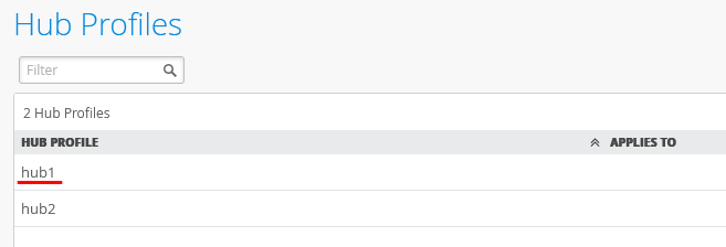
Under Applies To select “hub1-site” and “HUB1”.
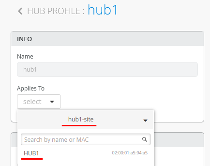
Click on Save.
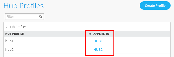
Repeat the process for the second hub in the second hub site so that in the end both hub profiles have their individual hub device assigned as shown below:
Wait about 10 minutes until the initial configuration is brought up for the first time and all changes are made and applied.
Test Your Network Configuration
We are now ready to test our configuration.
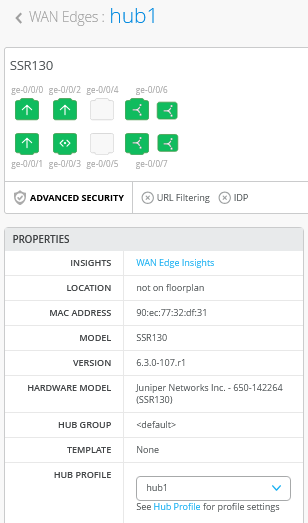
Go to WAN Edges -> site=hub1-site and click on “hub1”.
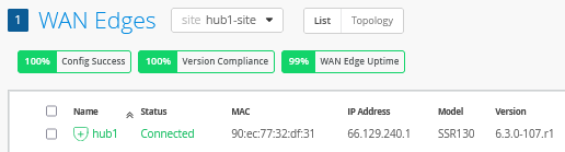
Review the device information.
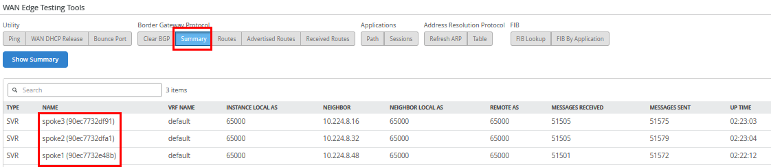
When you use Utilities -> Testing Tools and review the BGP neighbor summary, you will see only the three spokes connected and exchanging routes.
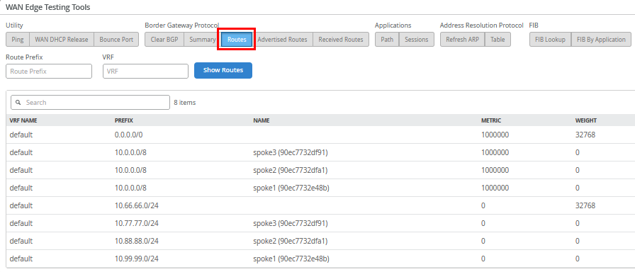
Also review the routes distributed in the VPN.
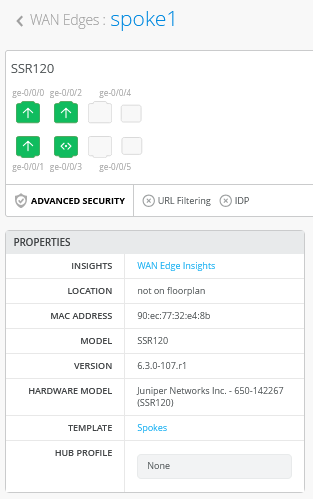
Go to WAN Edges -> site=spoke1-site and click on “spoke1”.
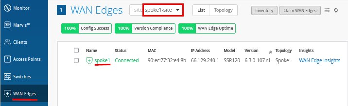
Review the device information.
Review the topology details with the four tunnels this spoke has established to the two hubs.
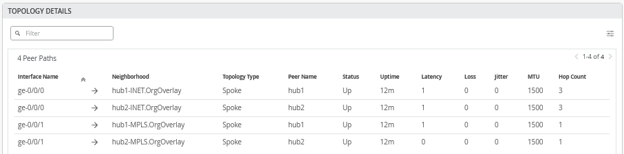
On the hubs, only tunnels to other hubs are displayed for scale reasons. You will see that in the next topology.
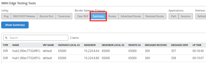
When you use Utilities -> Testing Tools and review the BGP neighbor summary, you will see only the two hubs are connected and exchanging routes.
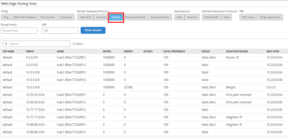
Also review the routes distributed in the VPN.
We shall now continue our testing on the clients attached to the
spokes. We attach to the desktop1 VM with IP address
10.99.99.99 attached to spoke1:
# try to reach the local WAN-Router interface desktop1 VM is attached to
root@desktop1:~# ping -c3 10.99.99.1
PING 10.99.99.1 (10.99.99.1) 56(84) bytes of data.
64 bytes from 10.99.99.1: icmp_seq=1 ttl=128 time=0.457 ms
64 bytes from 10.99.99.1: icmp_seq=2 ttl=128 time=0.329 ms
64 bytes from 10.99.99.1: icmp_seq=3 ttl=128 time=0.948 ms
#
# try to reach the client desktop2 VM attached to spoke2
# this causes relay on the hub for this traffic
root@desktop1:~# ping -c3 10.88.88.88
PING 10.88.88.88 (10.88.88.88) 56(84) bytes of data.
64 bytes from 10.88.88.88: icmp_seq=1 ttl=120 time=4.16 ms
64 bytes from 10.88.88.88: icmp_seq=2 ttl=120 time=1.32 ms
64 bytes from 10.88.88.88: icmp_seq=3 ttl=120 time=1.24 ms
#
# try to reach the client desktop3 VM attached to spoke3
# this causes relay on the hub for this traffic
root@desktop1:~# ping -c3 10.77.77.77
PING 10.77.77.77 (10.77.77.77) 56(84) bytes of data.
64 bytes from 10.77.77.77: icmp_seq=1 ttl=122 time=12.4 ms
64 bytes from 10.77.77.77: icmp_seq=2 ttl=122 time=1.28 ms
64 bytes from 10.77.77.77: icmp_seq=3 ttl=122 time=1.25 ms
#
# try to reach the client desktop4 VM attached to hub1
root@desktop1:~# ping -c3 10.66.66.66
PING 10.66.66.66 (10.66.66.66) 56(84) bytes of data.
64 bytes from 10.66.66.66: icmp_seq=1 ttl=59 time=4.54 ms
64 bytes from 10.66.66.66: icmp_seq=2 ttl=59 time=1.13 ms
64 bytes from 10.66.66.66: icmp_seq=3 ttl=59 time=1.13 ms
#
# try to reach the client desktop5 VM attached to hub2
root@desktop1:~# ping -c3 10.55.55.55
PING 10.55.55.55 (10.55.55.55) 56(84) bytes of data.
64 bytes from 10.55.55.55: icmp_seq=1 ttl=59 time=4.29 ms
64 bytes from 10.55.55.55: icmp_seq=2 ttl=59 time=1.14 ms
64 bytes from 10.55.55.55: icmp_seq=3 ttl=59 time=0.968 ms
#
# let a continued ping to the internet run
# in our case all traffic is sent to hub for central breakout
root@desktop1:~# ping 8.8.8.8
PING 8.8.8.8 (8.8.8.8) 56(84) bytes of data.
64 bytes from 8.8.8.8: icmp_seq=1 ttl=47 time=8.43 ms
64 bytes from 8.8.8.8: icmp_seq=2 ttl=47 time=3.83 ms
64 bytes from 8.8.8.8: icmp_seq=3 ttl=47 time=3.84 ms
64 bytes from 8.8.8.8: icmp_seq=4 ttl=47 time=3.98 ms
64 bytes from 8.8.8.8: icmp_seq=5 ttl=47 time=3.82 ms
.
.
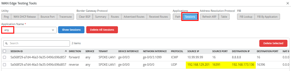
Use Utilities -> Testing Tools to review the
application sessions with Application Name=any. Due to
the reverse flow, we see that the traffic is received from
Hub2’s Internet public IP address
192.168.129.201.
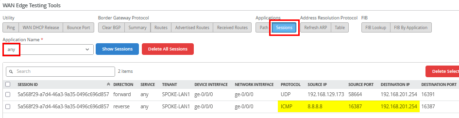
Do the same for the second hub by going to WAN Edges
-> site=hub2-site and clicking on “hub2”.
Then go to Utilities -> Testing Tools and
review the application sessions with Application
Name=any again. Here, you can see the reverse flow
ICMP responses to the source NATed Interface ge-0/0/0
where we forwarded our traffic to.
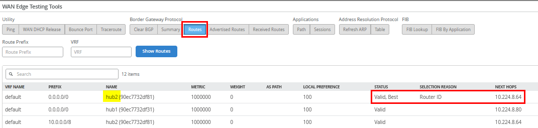
If you're wondering why traffic wasn't routed to Hub1, check the FIB routes on Spoke1. Hub2 is preferred because, although both hubs advertised the same default route (0.0.0.0/0), Hub2 had a lower internal Router ID (or BGPoSVR loopback IP) than Hub1, making it the preferred path.
You can also verify this through the FIB created for the
Application=any as below:
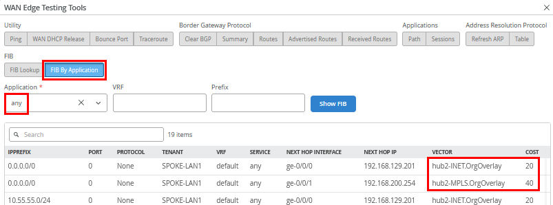
In case you do not want Hub2 as the default router, follow the instructions in Changing the Hub Used for Central Breakout When Traffic Destination Is “Any” .
The remaining testing is done with the clients attached to the
hubs. We connect to the desktop4 VM with IP address
10.66.66.66 attached to Hub1:
# try to reach the client desktop1 VM attached to spoke1
root@desktop4:~# ping -c3 10.99.99.99
PING 10.99.99.99 (10.99.99.99) 56(84) bytes of data.
64 bytes from 10.99.99.99: icmp_seq=1 ttl=59 time=4.98 ms
64 bytes from 10.99.99.99: icmp_seq=2 ttl=59 time=1.07 ms
64 bytes from 10.99.99.99: icmp_seq=3 ttl=59 time=1.03 ms
#
# try to reach the client desktop2 VM attached to spoke2
root@desktop4:~# ping -c3 10.88.88.88
PING 10.88.88.88 (10.88.88.88) 56(84) bytes of data.
64 bytes from 10.88.88.88: icmp_seq=1 ttl=59 time=5.49 ms
64 bytes from 10.88.88.88: icmp_seq=2 ttl=59 time=1.15 ms
64 bytes from 10.88.88.88: icmp_seq=3 ttl=59 time=1.06 ms
#
# try to reach the client desktop3 VM attached to spoke3
root@desktop4:~# ping -c3 10.77.77.77
PING 10.77.77.77 (10.77.77.77) 56(84) bytes of data.
64 bytes from 10.77.77.77: icmp_seq=1 ttl=59 time=7.07 ms
64 bytes from 10.77.77.77: icmp_seq=2 ttl=59 time=1.21 ms
64 bytes from 10.77.77.77: icmp_seq=3 ttl=59 time=1.04 ms
#
# try services on the internet using the local breakout on the hub
root@desktop4:~# ping -c3 8.8.8.8
PING 8.8.8.8 (8.8.8.8) 56(84) bytes of data.
64 bytes from 8.8.8.8: icmp_seq=1 ttl=109 time=3.10 ms
64 bytes from 8.8.8.8: icmp_seq=2 ttl=109 time=2.67 ms
64 bytes from 8.8.8.8: icmp_seq=3 ttl=109 time=2.68 ms
#
# try to reach the client desktop5 VM attached to hub2
# It's expected NOT to work as hub to hub traffic will be done in the next topology
root@desktop4:~# ping -c3 10.55.55.55
PING 10.55.55.55 (10.55.55.55) 56(84) bytes of data.
.
--- 10.55.55.55 ping statistics ---
3 packets transmitted, 0 received, 100% packet loss, time 2043ms
For the last test, we connect to the desktop5 VM with IP address
10.55.55.55 attached to Hub2:
# try to reach the client desktop1 VM attached to spoke1
root@desktop5:~# ping -c3 10.99.99.99
PING 10.99.99.99 (10.99.99.99) 56(84) bytes of data.
64 bytes from 10.99.99.99: icmp_seq=1 ttl=61 time=4.21 ms
64 bytes from 10.99.99.99: icmp_seq=2 ttl=61 time=1.01 ms
64 bytes from 10.99.99.99: icmp_seq=3 ttl=61 time=1.02 ms
#
# try to reach the client desktop2 VM attached to spoke2
root@desktop5:~# ping -c3 10.88.88.88
PING 10.88.88.88 (10.88.88.88) 56(84) bytes of data.
64 bytes from 10.88.88.88: icmp_seq=1 ttl=59 time=4.95 ms
64 bytes from 10.88.88.88: icmp_seq=2 ttl=59 time=1.14 ms
64 bytes from 10.88.88.88: icmp_seq=3 ttl=59 time=1.12 ms
#
# try to reach the client desktop3 VM attached to spoke3
root@desktop5:~# ping -c3 10.77.77.77
PING 10.77.77.77 (10.77.77.77) 56(84) bytes of data.
64 bytes from 10.77.77.77: icmp_seq=1 ttl=59 time=4.83 ms
64 bytes from 10.77.77.77: icmp_seq=2 ttl=59 time=1.22 ms
64 bytes from 10.77.77.77: icmp_seq=3 ttl=59 time=1.32 ms
#
# try services on the internet using the local breakout on the hub
root@desktop5:~# ping -c3 8.8.8.8
PING 8.8.8.8 (8.8.8.8) 56(84) bytes of data.
64 bytes from 8.8.8.8: icmp_seq=1 ttl=51 time=3.75 ms
64 bytes from 8.8.8.8: icmp_seq=2 ttl=51 time=3.48 ms
64 bytes from 8.8.8.8: icmp_seq=3 ttl=51 time=3.35 ms
#
# try to reach the client desktop4 VM attached to hub1
# It's expected NOT to work as hub to hub traffic will be done in the next topology
root@desktop5:~# ping -c3 10.44.44.44
PING 10.44.44.44 (10.44.44.44) 56(84) bytes of data.
.
--- 10.44.44.44 ping statistics ---
3 packets transmitted, 0 received, 100% packet loss, time 2027ms