Appendix: Building an Extended Full Stack Topology with Juniper EX Switch Virtual Chassis and SSR HA Cluster
The last topology tested as part of this JVD is an extension of the lab from Appendix: Building a Full Stack Topology with Juniper EX Switch and Juniper AP. The configuration for a Virtual Chassis connected to a single spoke is omitted, as the only additional step for improved resiliency is connecting one of the downlinks to the backup member of the Virtual Chassis. In this lab we configure:
- A redundant high availability cluster spoke while you still have two separate hubs.
- A Virtual Chassis is built using Juniper EX Series Switches, with two uplinks connected to the WAN router nodes as shown in the topology diagram below, providing resiliency.
- A new network with the range 10.11.11.0/24 is added to all spokes to simulate a guest Wi-Fi network. This network is restricted from sending traffic into the VPN. In this lab setup, guest traffic is allowed to use local Internet breakout. Later, the goal is to route all guest traffic to a cloud service for inspection and compliance filtering before it reaches the Internet.
.png)
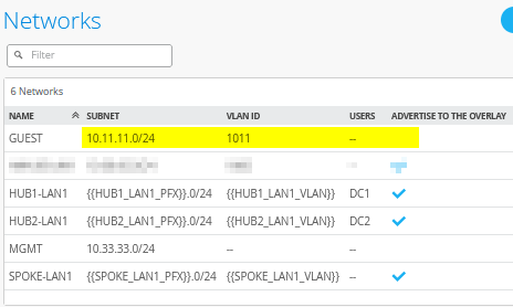
Create a Wi-Fi Guest Network
Go to Organization -> Networks. Configure the first network in the following way:
- Name=
GUEST - Subnet IP Address=
10.11.11.0. This will be the same on all sites. - Prefix Length=
24 - VLAN ID=
1011 - Access to Mist Cloud=
Unchecked/Disabled. This should not be needed for guests. - Advertised via Overlay=
Unchecked/Disabled. This is mandatory here as we can’t have the same IP address range announced from multiple sites.
The result should look like the figure below:
Create a WAN Edge Template for HA Spoke with LAG
Go to Organization -> WAN Edge Templates.
Should you choose to use the import option, click on Import Profile and import the below JSON as a file.
{
  "type": "spoke",
  "dhcpd_config": {
    "enabled": true,
    "SPOKE-LAN1": {
      "type": "local",
      "ip_start": "{{SPOKE_LAN1_PFX}}.10",
      "ip_end": "{{SPOKE_LAN1_PFX}}.250",
      "gateway": "{{SPOKE_LAN1_PFX}}.1",
      "dns_servers": [
        "8.8.8.8",
        "9.9.9.9"
      ],
      "options": {},
      "lease_time": 86400,
      "fixed_bindings": {}
    },
    "MGMT": {
      "type": "local",
      "ip_start": "10.33.33.10",
      "ip_end": "10.33.33.250",
      "gateway": "10.33.33.1",
      "dns_servers": [
        "8.8.8.8",
        "9.9.9.9"
      ],
      "options": {},
      "lease_time": 86400,
      "fixed_bindings": {}
    },
    "GUEST": {
      "type": "local",
      "ip_start": "10.11.11.10",
      "ip_end": "10.11.11.250",
      "gateway": "10.11.11.1",
      "dns_servers": [
        "8.8.8.8",
        "9.9.9.9"
      ],
      "options": {},
      "lease_time": 86400,
      "fixed_bindings": {}
    }
  },
  "ntpOverride": true,
  "dnsOverride": true,
  "service_policies": [
    {
      "name": "spoke-to-hub-dmz",
      "tenants": [
        "SPOKE-LAN1"
      ],
      "services": [
        "HUB1-LAN1",
        "HUB2-LAN1"
      ],
      "action": "allow",
      "idp": {
        "enabled": false
      },
      "path_preference": "VPN"
    },
    {
      "name": "hub-dmz-to-spoke",
      "tenants": [
        "HUB1-LAN1",
        "HUB2-LAN1"
      ],
      "services": [
        "SPOKE-LAN1"
      ],
      "action": "allow",
      "path_preference": "LAN",
      "idp": {
        "enabled": false
      }
    },
    {
      "name": "spoke-to-spoke-via-hub",
      "tenants": [
        "SPOKE-LAN1"
      ],
      "services": [
        "SPOKE-LAN1"
      ],
      "action": "allow",
      "idp": {
        "enabled": false
      },
      "local_routing": true
    },
    {
      "name": "mgmt-to-mist-cloud",
      "tenants": [
        "MGMT"
      ],
      "services": [
        "any"
      ],
      "action": "allow",
      "path_preference": "LBO",
      "idp": {
        "enabled": false
      }
    },
    {
      "name": "guest-to-lbo",
      "tenants": [
        "GUEST"
      ],
      "services": [
        "any"
      ],
      "action": "allow",
      "path_preference": "LBO",
      "idp": {
        "enabled": false
      }
    },
    {
      "tenants": [
        "SPOKE-LAN1"
      ],
      "services": [
        "any"
      ],
      "action": "allow",
      "name": "internet-via-hub-cbo",
      "idp": {
        "enabled": false
      },
      "path_preference": "VPN"
    }
  ],
  "ip_configs": {
    "SPOKE-LAN1": {
      "type": "static",
      "ip": "{{SPOKE_LAN1_PFX}}.1",
      "netmask": "/24"
    },
    "MGMT": {
      "type": "static",
      "ip": "10.33.33.1"
    },
    "GUEST": {
      "type": "static",
      "ip": "10.11.11.1"
    }
  },
  "dns_servers": [
    "8.8.8.8",
    "9.9.9.9"
  ],
  "port_config": {
    "ge-0/0/0": {
      "name": "N0-INET",
      "usage": "wan",
      "aggregated": false,
      "redundant": false,
      "critical": false,
      "disabled": false,
      "wan_type": "broadband",
      "ip_config": {
        "type": "dhcp"
      },
      "disable_autoneg": false,
      "wan_source_nat": {
        "disabled": false
      },
      "vpn_paths": {
        "hub1-INET.OrgOverlay": {
          "bfd_profile": "broadband",
          "role": "spoke"
        },
        "hub2-INET.OrgOverlay": {
          "bfd_profile": "broadband",
          "role": "spoke"
        }
      }
    },
    "ge-1/0/0": {
      "name": "N1-INET",
      "usage": "wan",
      "aggregated": false,
      "redundant": false,
      "critical": false,
      "disabled": false,
      "wan_type": "broadband",
      "ip_config": {
        "type": "dhcp"
      },
      "disable_autoneg": false,
      "wan_source_nat": {
        "disabled": false
      },
      "vpn_paths": {
        "hub1-INET.OrgOverlay": {
          "role": "spoke",
          "bfd_profile": "broadband"
        },
        "hub2-INET.OrgOverlay": {
          "role": "spoke",
          "bfd_profile": "broadband"
        }
      }
    },
    "ge-0/0/1,ge-1/0/1": {
      "name": "HA-MPLS",
      "usage": "wan",
      "aggregated": false,
      "redundant": true,
      "reth_idx": 1,
      "reth_node": "node0",
      "critical": false,
      "disabled": false,
      "wan_type": "broadband",
      "ip_config": {
        "type": "static",
        "ip": "{{WAN1_PFX}}.2",
        "netmask": "/24",
        "gateway": "{{WAN1_PFX}}.1"
      },
      "disable_autoneg": false,
      "wan_source_nat": {
        "disabled": false
      },
      "vpn_paths": {
        "hub1-MPLS.OrgOverlay": {
          "role": "spoke",
          "bfd_profile": "broadband"
        },
        "hub2-MPLS.OrgOverlay": {
          "role": "spoke",
          "bfd_profile": "broadband"
        }
      }
    },
    "ge-0/0/4,ge-0/0/5,ge-1/0/4,ge-1/0/5": {
      "networks": [
        "SPOKE-LAN1",
        "MGMT",
        "GUEST"
      ],
      "usage": "lan",
      "aggregated": true,
      "ae_disable_lacp": false,
      "ae_lacp_force_up": true,
      "ae_idx": "0",
      "redundant": true,
      "reth_idx": 4,
      "reth_node": "node0",
      "critical": false,
      "disabled": false
    }
  },
  "bgp_config": {},
  "routing_policies": {},
  "extra_routes": {},
  "path_preferences": {
    "VPN": {
      "strategy": "weighted",
      "paths": [
        {
          "name": "hub1-INET.OrgOverlay",
          "cost": 10,
          "type": "vpn"
        },
        {
          "name": "hub2-INET.OrgOverlay",
          "cost": 20,
          "type": "vpn"
        },
        {
          "name": "hub1-MPLS.OrgOverlay",
          "cost": 30,
          "type": "vpn"
        },
        {
          "name": "hub2-MPLS.OrgOverlay",
          "cost": 40,
          "type": "vpn"
        }
      ]
    },
    "LAN": {
      "strategy": "ordered",
      "paths": [
        {
          "type": "local",
          "networks": [
            "SPOKE-LAN1"
          ]
        }
      ]
    },
    "LBO": {
      "strategy": "ordered",
      "paths": [
        {
          "name": "N0-INET",
          "type": "wan"
        },
        {
          "name": "N1-INET",
          "type": "wan"
        }
      ]
    }
  },
  "ospf_areas": {},
  "vrf_instances": {},
  "tunnel_configs": {},
  "oob_ip_config": {
    "type": "dhcp",
    "node1": {
      "type": "dhcp"
    }
  },
  "tunnel_provider_options": {
    "jse": {},
    "zscaler": {}
  },
  "ospf_config": {
    "enabled": false,
    "areas": {}
  },
  "name": "haspoke-with-lag"
}
Should you decide to configure everything manually in the Juniper Mist portal, then use the following steps.
We recommend you clone the existing “Spokes-with-LAN-LAG” template and name the new template “haspoke-with-lag”. Then make the following changes as the WAN and LAN interfaces change with the high-availability configuration.
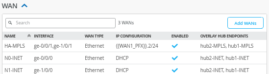
Delete all prior WAN interfaces and add the following three new WAN interfaces.
Configure a first WAN interface for Node0 as follows:
- Name=
N0-INET. This indicates which topology and node it’s going to use. - WAN Type=
Ethernet - Interface=
ge-0/0/0as all interfaces starting withge-0are on Node0. - IP Configuration=
DHCP - Source NAT=
Interface - Overlay Hub Endpoints
- Endpoint1=
hub1-INET - BFD Profile1=
Broadband - Endpoint2=
hub2-INET - BFD Profile2=
Broadband
- Endpoint1=
Then configure the first WAN interface for Node1 as follows:
- Name=
N1-INET. This indicates which topology and node it’s going to use. - WAN Type=
Ethernet - Interface=
ge-1/0/0as all interfaces starting withge-1are on Node1. - IP Configuration=
DHCP - Source NAT=
Interface - Overlay Hub Endpoints
- Endpoint1=
hub1-INET - BFD Profile1=
Broadband - Endpoint2=
hub2-INET - BFD Profile2=
Broadband
- Endpoint1=
Then, configure the third and redundant WAN interface for the MPLS path for Node0 and Node1 as follows:
- Name=
HA-MPLS. This indicates which topology and node it’s going to use. - WAN Type=
Ethernet - Interface=
ge-0/0/1andge-1/0/1 - Redundant=Checked/Enabled
- Redundant Index=1. This is not required for an SSR, but we add for compatibility.
- Primary Node=node0
- IP Configuration=
Static -
IP Address={{WAN1_PFX}}.2 -
Prefix Length=24 -
Gateway={{WAN1_PFX}}.1 - Source NAT=
Interface - Overlay Hub Endpoints
- Endpoint1=
hub1-MPLS - BFD Profile1=
Broadband - Endpoint2=
hub2-MPLS - BFD Profile2=
Broadband
- Endpoint1=
The result should look like the figure below:
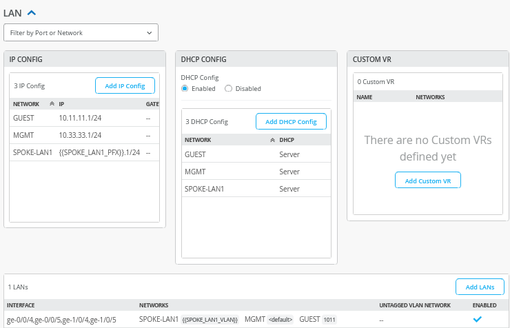
In the LAN section, we need to add the following IP Configuration:
- Network=
GUEST - IP Address=
10.11.11.1 - Prefix Length=
24
Then, we create an additional DHCP server for this network with the following configuration:
- Network=
GUEST - DHCP=
Server - IP Start=
10.11.11.10 - IP End=
10.11.11.250 - Gateway=
10.11.11.1 - Maximum Lease Time=
86400 - DNS Servers=
8.8.8.8, 9.9.9.9
Delete the existing LAN interface configuration and create the following new LAG + redundant interface:
- Interface=
ge-0/0/4,ge-0/0/5,ge-1/0/4,ge-1/0/5 - Port Aggregation=
Checked/Enabled- Disable LACP=
Unchecked/Disabled - Enable Force Up=
Checked/Enabled - AE Index=0
- Disable LACP=
- Redundant=
Checked/Enabled-
Redundant Index=4 -
Primary Node=node0
-
-
Networks=SPOKE-LAN1 + GUEST + MGMT -
Untagged VLAN Network=None
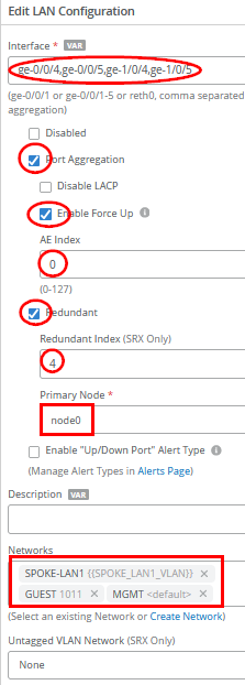
The result should look like the figure below:
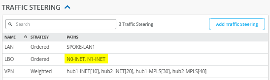
You need to change the existing “LBO” traffic steering profile for the Node0 and Node1 redundant WAN interfaces in the following way:
- Name=
LBO - Strategy=Ordered
- Paths
- Path1 Type=
WAN: N0-INET - Path2 Type=
WAN: N1-INET
- Path1 Type=
The result should look like the figure below:
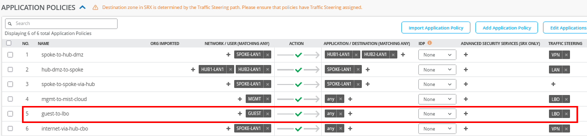
Insert the following application policy:
- Number=
5- Name=
guest-to-lbo - Network=
GUEST - Action=
Pass - Application=
any - Traffic Steering=
LBO
- Name=
The result should look like the figure below:
Remaining Tasks for This Lab
First you need to assign the new spoke templates to their sites.
Go to Organization -> WAN Edge Templates -> “haspoke-with-lag” template and click Assign to Sites. Then, you assign spoke2-site to this template.
If you have the spoke devices in use from previous labs, then go to the inventory and release them. This will bring them back into a factory state.
Here, we describe how to build a cluster during the onboarding assuming all devices are in a factory default state.
Go to Organization -> Inventory and select WAN Edges and click Claim WAN Edges. Then, do the following:
- Assign claimed WAN Edge to
site=
Unchecked/Disabled - Enter the claim codes for the two devices.
.png)
This will claim the two devices without assigning them to a site.
.png)
Select the two devices and click on Assign To Site from the More menu.
.png)
Now configure:
- Assign 2 selected WAN Edges to
site=
spoke2-site - Create Cluster=
Checked/Enabled - Select a device to act as node0 = select that as required
- Manage Configuration with Mist=
Enabled(automatically)
.png)
This will commit the needed cluster configuration for the HA Spoke.
Test Your Network Configuration
We are now ready to test our configuration. In our case, you'll notice the following differences compared to the lab setup described in the previous section:
- The reported MAC address of the WAN router will now be
00:00:5e:00:01:01as the LAG also has a redundant VRRP configuration. - The Virtual Chassis was already built automatically before, depending on the EX Series Switch model, when following the appropriate power-up sequence. Please review the Day 0 section in the JVD for Distributed Branch EX Series for more information.
With the redundant spoke configuration on Spoke2 in place and a console cable attached to the switch, you can evaluate the following.
# ensure you ask for a new DHCP-Lease
root@switch1> restart dhcp-service
Junos Dynamic Host Configuration Protocol process started, pid 55092
#
# wait a few seconds
#
# review your routing table
root@switch1> show route
.
inet.0: 3 destinations, 3 routes (3 active, 0 holddown, 0 hidden)
Limit/Threshold: 32768/32768 destinations
+ = Active Route, - = Last Active, * = Both
.
0.0.0.0/0          *[Access-internal/12] 00:00:14, metric 0
                    >  to 10.33.33.1 via irb.0
10.33.33.0/24      *[Direct/0] 00:00:14
                    >  via irb.0
10.33.33.11/32     *[Local/0] 00:00:14
                       Local via irb.0
.
#
# review MAC-Table
root@switch1> show ethernet-switching table
.
MAC flags (S - static MAC, D - dynamic MAC, L - locally learned, P - Persistent static, C - Control MAC
           SE - statistics enabled, NM - non configured MAC, R - remote PE MAC, O - ovsdb MAC
           GBP - group based policy)
.
Ethernet switching table : 3 entries, 3 learned
Routing instance : default-switch
    Vlan                MAC                 MAC         Age   GBP     Logical                NH        RTR
    name                address             flags             Tag     interface              Index     ID
    default             00:00:5e:00:01:01   D             -            ge-0/0/6.0             0         0
    default             d4:20:b0:01:46:81   D             -            ge-0/0/3.0             0         0
    default             d4:20:b0:01:46:bb   D             -            ge-1/0/3.0             0         0
#
# review IP address via ARP from WAN-Router received from an interface
root@switch1> show arp no-resolve
MAC Address       Address         Interface                Flags
00:00:5e:00:01:01 10.33.33.1      irb.0 [ge-0/0/6.0]       none
#
# confirm DNS and internet access
root@switch1> ping www.google.com inet
PING www.google.com (172.217.12.100): 56 data bytes
64 bytes from 172.217.12.100: icmp_seq=0 ttl=110 time=10.619 ms
64 bytes from 172.217.12.100: icmp_seq=1 ttl=110 time=11.276 ms
64 bytes from 172.217.12.100: icmp_seq=2 ttl=110 time=7.940 ms
^C
The test above shows that the switch obtained a DHCP lease and should be able to initiate traffic with the Juniper Mist cloud to be managed. The remaining steps to onboard an EX Series Switch are explained in the JVD Distributed Branch EX Series. In the Day 1 section, review the sections shown in the figure below:
.png)
This section does not repeat the traffic topology tests, as the changes introduced are minimal. For detailed testing procedures, please refer to the Test Your Network Configuration section in the first topology.