Appendix: Building a Full Stack Topology with Juniper EX Switch and Juniper AP
This lab is an extension of the previous lab Appendix: Building a base SD-WAN Topology with Three Spokes and Two Hubs. There are no hub configuration changes to be made as we do not touch the VPN configuration. We add the following changes to this lab:
- We define a new network intended to manage switches and APs
attached to the WAN router.
- This network will have the same IP address range
10.33.33.0/24on all sites. - We do not propagate this IP address range to the VPN overlay.
- This traffic will use local breakout on the WAN router to reach the Juniper Mist cloud managing it.
- The WAN router will have a local DHCP server to hand out leases to the attached devices.
- The network needs to be native at the LAN interface as the switch ports are initially in access mode.
- This network will have the same IP address range
- On Spoke1, we use the interface
ge-0/0/2as the downlink to the switch. Hence, we assume this branch has no link redundancy requirement to the switch and attached APs. - On Spoke2, we use the interfaces
ge-0/0/4andge-0/0/5as downlinks to the switch. Hence, we can build a LAG with LACP toward the switch to achieve redundancy and load-balancing for more throughput. We also utilize a feature called force-up to the attached switch to be able to reach the Juniper Mist cloud without an initial LAG configuration. This is further documented in the JVD for Distributed Branch EX Series . Please review for more details on switch management towards Juniper Mist cloud and on the advantages of force-up when using a LAG.
.png)
When using force-up with a LAG, you must use firmware 6.3.0 or higher for Session Smart Routers.
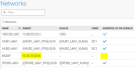
Create a Management Network
Go to Organization -> Networks. Configure the first network in the following way:
- Name=
MGMT - Subnet IP Address=
10.33.33.0(this will be the same on all sites) - Prefix Length=
24 - VLAN ID=
<default>/noneThis ensures that it will be native on the trunk interface downlink to the switch. - Access to Mist Cloud=
Checked/Enabled. This is mandatory to be able to manage the attached devices. - Advertised via Overlay=
Unchecked/Disabled. This is mandatory as we can’t have the same IP address range announced from multiple sites.
The result should look like the figure below:
Extend the WAN Edge Template for Spoke with One Downlink
Go to Organization -> WAN Edge Templates.
Should you choose to use the import option, click on Import Profile and import the below JSON as a file.
{
  "dhcpd_config": {
    "enabled": true,
    "SPOKE-LAN1": {
      "type": "local",
      "ip_start": "{{SPOKE_LAN1_PFX}}.10",
      "ip_end": "{{SPOKE_LAN1_PFX}}.250",
      "gateway": "{{SPOKE_LAN1_PFX}}.1",
      "dns_servers": [
        "8.8.8.8",
        "9.9.9.9"
      ],
      "options": {},
      "lease_time": 86400,
      "fixed_bindings": {}
    },
    "MGMT": {
      "type": "local",
      "ip_start": "10.33.33.10",
      "ip_end": "10.33.33.250",
      "gateway": "10.33.33.1",
      "dns_servers": [
        "8.8.8.8",
        "9.9.9.9"
      ],
      "options": {},
      "lease_time": 86400,
      "fixed_bindings": {}
    }
  },
  "ntpOverride": true,
  "dnsOverride": true,
  "service_policies": [
    {
      "name": "spoke-to-hub-dmz",
      "tenants": [
        "SPOKE-LAN1"
      ],
      "services": [
        "HUB1-LAN1",
        "HUB2-LAN1"
      ],
      "action": "allow",
      "idp": {
        "enabled": false
      },
      "path_preference": "VPN"
    },
    {
      "name": "hub-dmz-to-spoke",
      "tenants": [
        "HUB1-LAN1",
        "HUB2-LAN1"
      ],
      "services": [
        "SPOKE-LAN1"
      ],
      "action": "allow",
      "path_preference": "LAN",
      "idp": {
        "enabled": false
      }
    },
    {
      "name": "spoke-to-spoke-via-hub",
      "tenants": [
        "SPOKE-LAN1"
      ],
      "services": [
        "SPOKE-LAN1"
      ],
      "action": "allow",
      "idp": {
        "enabled": false
      },
      "local_routing": true
    },
    {
      "name": "mgmt-to-mist-cloud",
      "tenants": [
        "MGMT"
      ],
      "services": [
        "any"
      ],
      "action": "allow",
      "path_preference": "LBO",
      "idp": {
        "enabled": false
      }
    },
    {
      "tenants": [
        "SPOKE-LAN1"
      ],
      "services": [
        "any"
      ],
      "action": "allow",
      "name": "internet-via-hub-cbo",
      "idp": {
        "enabled": false
      },
      "path_preference": "VPN"
    }
  ],
  "ip_configs": {
    "SPOKE-LAN1": {
      "type": "static",
      "ip": "{{SPOKE_LAN1_PFX}}.1",
      "netmask": "/24"
    },
    "MGMT": {
      "type": "static",
      "ip": "10.33.33.1"
    }
  },
  "dns_servers": [
    "8.8.8.8",
    "9.9.9.9"
  ],
  "port_config": {
    "ge-0/0/0": {
      "name": "INET",
      "usage": "wan",
      "wan_type": "broadband",
      "aggregated": false,
      "redundant": false,
      "traffic_shaping": {
        "enabled": false
      },
      "ip_config": {
        "type": "dhcp"
      },
      "vpn_paths": {
        "hub1-INET.OrgOverlay": {
          "bfd_profile": "broadband",
          "role": "spoke"
        },
        "hub2-INET.OrgOverlay": {
          "bfd_profile": "broadband",
          "role": "spoke"
        }
      }
    },
    "ge-0/0/1": {
      "name": "MPLS",
      "usage": "wan",
      "wan_type": "broadband",
      "aggregated": false,
      "redundant": false,
      "traffic_shaping": {
        "enabled": false
      },
      "ip_config": {
        "type": "static",
        "ip": "{{WAN1_PFX}}.2",
        "netmask": "/24",
        "gateway": "{{WAN1_PFX}}.1"
      },
      "vpn_paths": {
        "hub1-MPLS.OrgOverlay": {
          "bfd_profile": "broadband",
          "role": "spoke"
        },
        "hub2-MPLS.OrgOverlay": {
          "bfd_profile": "broadband",
          "role": "spoke"
        }
      }
    },
    "ge-0/0/2": {
      "networks": [
        "SPOKE-LAN1",
        "MGMT"
      ],
      "usage": "lan",
      "aggregated": false,
      "redundant": false,
      "critical": false,
      "disabled": false
    }
  },
  "bgp_config": {},
  "routing_policies": {},
  "extra_routes": {},
  "path_preferences": {
    "VPN": {
      "strategy": "weighted",
      "paths": [
        {
          "name": "hub1-INET.OrgOverlay",
          "cost": 10,
          "type": "vpn"
        },
        {
          "name": "hub2-INET.OrgOverlay",
          "cost": 20,
          "type": "vpn"
        },
        {
          "name": "hub1-MPLS.OrgOverlay",
          "cost": 30,
          "type": "vpn"
        },
        {
          "name": "hub2-MPLS.OrgOverlay",
          "cost": 40,
          "type": "vpn"
        }
      ]
    },
    "LAN": {
      "strategy": "ordered",
      "paths": [
        {
          "type": "local",
          "networks": [
            "SPOKE-LAN1"
          ]
        }
      ]
    },
    "LBO": {
      "strategy": "ordered",
      "paths": [
        {
          "name": "INET",
          "type": "wan"
        }
      ]
    }
  },
  "ospf_areas": {},
  "vrf_instances": {},
  "tunnel_configs": {},
  "oob_ip_config": {
    "type": "dhcp",
    "node1": {
      "type": "dhcp"
    }
  },
  "tunnel_provider_options": {
    "jse": {},
    "zscaler": {}
  },
  "ospf_config": {
    "enabled": false,
    "areas": {}
  },
  "type": "spoke",
  "name": "Spokes"
}
Should you decide to configure everything manually in the Juniper Mist portal, then use the following steps.
We modify the existing “Spokes” template in the following way to get the additional management network configured.
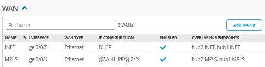
The WAN interface configuration does not need to be changed hence it should still look like the figure below:
In the LAN section, we need to add the following IP Configuration:
- Network=
MGMT - IP Address=
10.33.33.1 - Prefix Length=24
Then, we create an additional DHCP server for this network with the following configuration:
- Network=
MGMT - DHCP=
Server - IP Start=
10.33.33.10 - IP End=
10.33.33.250 - Gateway=
10.33.33.1 - Maximum Lease Time=
86400 - DNS Servers=
8.8.8.8, 9.9.9.9
The LAN interface configuration is then changed to the following configuration:
- Interface=
ge-0/0/2 - Networks=
SPOKE1-LAN1 + MGMT - Untagged VLAN=
None
The result should look like the figure below:

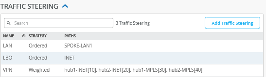
We now need to configure an additional traffic steering profile for local breakout of the management network as we do not need this to be part of the overlay VPN. Add an additional traffic steering rule with the following configuration:
- Name=
LBO - Strategy=
Ordered - Paths
- Path1 Type=
WAN: INET
- Path1 Type=
The result should look like the figure below:
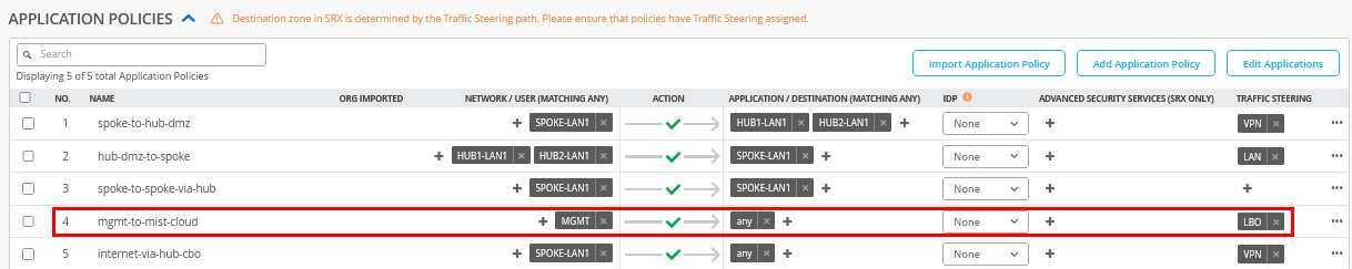
Insert the following application policy:
- Number=
4- Name=
mgmt-to-mist-cloud - Network=
MGMT - Action=
Pass - Application=
any - Traffic Steering=
LBO
- Name=
The result should look like the figure below:
Save your changes.
Create the WAN Edge Template for the Spoke with a LAG Towards the Switch
Go to Organization -> WAN Edge Templates.
Should you choose to use the import option, click on Import Profile and import the below JSON as a file.
{
  "type": "spoke",
  "dhcpd_config": {
    "enabled": true,
    "SPOKE-LAN1": {
      "type": "local",
      "ip_start": "{{SPOKE_LAN1_PFX}}.10",
      "ip_end": "{{SPOKE_LAN1_PFX}}.250",
      "gateway": "{{SPOKE_LAN1_PFX}}.1",
      "dns_servers": [
        "8.8.8.8",
        "9.9.9.9"
      ],
      "options": {},
      "lease_time": 86400,
      "fixed_bindings": {}
    },
    "MGMT": {
      "type": "local",
      "ip_start": "10.33.33.10",
      "ip_end": "10.33.33.250",
      "gateway": "10.33.33.1",
      "dns_servers": [
        "8.8.8.8",
        "9.9.9.9"
      ],
      "options": {},
      "lease_time": 86400,
      "fixed_bindings": {}
    }
  },
  "ntpOverride": true,
  "dnsOverride": true,
  "service_policies": [
    {
      "name": "spoke-to-hub-dmz",
      "tenants": [
        "SPOKE-LAN1"
      ],
      "services": [
        "HUB1-LAN1",
        "HUB2-LAN1"
      ],
      "action": "allow",
      "idp": {
        "enabled": false
      },
      "path_preference": "VPN"
    },
    {
      "name": "hub-dmz-to-spoke",
      "tenants": [
        "HUB1-LAN1",
        "HUB2-LAN1"
      ],
      "services": [
        "SPOKE-LAN1"
      ],
      "action": "allow",
      "path_preference": "LAN",
      "idp": {
        "enabled": false
      }
    },
    {
      "name": "spoke-to-spoke-via-hub",
      "tenants": [
        "SPOKE-LAN1"
      ],
      "services": [
        "SPOKE-LAN1"
      ],
      "action": "allow",
      "idp": {
        "enabled": false
      },
      "local_routing": true
    },
    {
      "name": "mgmt-to-mist-cloud",
      "tenants": [
        "MGMT"
      ],
      "services": [
        "any"
      ],
      "action": "allow",
      "path_preference": "LBO",
      "idp": {
        "enabled": false
      }
    },
    {
      "tenants": [
        "SPOKE-LAN1"
      ],
      "services": [
        "any"
      ],
      "action": "allow",
      "name": "internet-via-hub-cbo",
      "idp": {
        "enabled": false
      },
      "path_preference": "VPN"
    }
  ],
  "ip_configs": {
    "SPOKE-LAN1": {
      "type": "static",
      "ip": "{{SPOKE_LAN1_PFX}}.1",
      "netmask": "/24"
    },
    "MGMT": {
      "type": "static",
      "ip": "10.33.33.1"
    }
  },
  "dns_servers": [
    "8.8.8.8",
    "9.9.9.9"
  ],
  "port_config": {
    "ge-0/0/0": {
      "name": "INET",
      "usage": "wan",
      "wan_type": "broadband",
      "aggregated": false,
      "redundant": false,
      "traffic_shaping": {
        "enabled": false
      },
      "ip_config": {
        "type": "dhcp"
      },
      "vpn_paths": {
        "hub1-INET.OrgOverlay": {
          "bfd_profile": "broadband",
          "role": "spoke"
        },
        "hub2-INET.OrgOverlay": {
          "bfd_profile": "broadband",
          "role": "spoke"
        }
      }
    },
    "ge-0/0/1": {
      "name": "MPLS",
      "usage": "wan",
      "wan_type": "broadband",
      "aggregated": false,
      "redundant": false,
      "traffic_shaping": {
        "enabled": false
      },
      "ip_config": {
        "type": "static",
        "ip": "{{WAN1_PFX}}.2",
        "netmask": "/24",
        "gateway": "{{WAN1_PFX}}.1"
      },
      "vpn_paths": {
        "hub1-MPLS.OrgOverlay": {
          "bfd_profile": "broadband",
          "role": "spoke"
        },
        "hub2-MPLS.OrgOverlay": {
          "bfd_profile": "broadband",
          "role": "spoke"
        }
      }
    },
    "ge-0/0/4,ge-0/0/5": {
      "networks": [
        "SPOKE-LAN1",
        "MGMT"
      ],
      "usage": "lan",
      "aggregated": true,
      "ae_disable_lacp": false,
      "ae_lacp_force_up": true,
      "ae_idx": "0",
      "redundant": false,
      "critical": false,
      "disabled": false
    }
  },
  "bgp_config": {},
  "routing_policies": {},
  "extra_routes": {},
  "path_preferences": {
    "VPN": {
      "strategy": "weighted",
      "paths": [
        {
          "name": "hub1-INET.OrgOverlay",
          "cost": 10,
          "type": "vpn"
        },
        {
          "name": "hub2-INET.OrgOverlay",
          "cost": 20,
          "type": "vpn"
        },
        {
          "name": "hub1-MPLS.OrgOverlay",
          "cost": 30,
          "type": "vpn"
        },
        {
          "name": "hub2-MPLS.OrgOverlay",
          "cost": 40,
          "type": "vpn"
        }
      ]
    },
    "LAN": {
      "strategy": "ordered",
      "paths": [
        {
          "type": "local",
          "networks": [
            "SPOKE-LAN1"
          ]
        }
      ]
    },
    "LBO": {
      "strategy": "ordered",
      "paths": [
        {
          "name": "INET",
          "type": "wan"
        }
      ]
    }
  },
  "ospf_areas": {},
  "vrf_instances": {},
  "tunnel_configs": {},
  "oob_ip_config": {
    "type": "dhcp",
    "node1": {
      "type": "dhcp"
    }
  },
  "tunnel_provider_options": {
    "jse": {},
    "zscaler": {}
  },
  "ospf_config": {
    "enabled": false,
    "areas": {}
  },
  "name": "Spokes-with-LAN-LAG"
}
Should you decide to configure everything manually in the Juniper Mist portal, then use the following steps.
We recommend you clone the existing “Spokes” template that we modified already in the last section for this lab and name the new template “Spokes-with-LAN-LAG”.
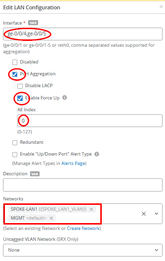
Then, we only need to change the LAN interface configuration with the following configuration:
- Interface=
ge-0/0/4,ge-0/0/5 - Port Aggregation=
Checked/Enabled- Disable LACP=
Unchecked/Disabled - Enable Force Up=
Checked/Enabled - AE Index=
0
- Disable LACP=
- Networks=
SPOKE1-LAN1 + MGMT - Untagged VLAN=
None
Save your changes and then apply this template to spoke2-site.
Test Your Network Configuration
We are now ready to test our configuration. With the single downlink spoke configuration on Spoke1 in place and a console cable to the switch, you can evaluate the following:
# ensure you ask for a new DHCP-Lease
root@switch1> restart dhcp-service
Junos Dynamic Host Configuration Protocol process started, pid 55092
#
# wait a few seconds
#
# review your routing table
root@switch1> show route
.
inet.0: 3 destinations, 3 routes (3 active, 0 holddown, 0 hidden)
Limit/Threshold: 32768/32768 destinations
+ = Active Route, - = Last Active, * = Both
.
0.0.0.0/0 *[Access-internal/12] 00:00:02, metric 0
> to 10.33.33.1 via irb.0
10.33.33.0/24 *[Direct/0] 00:00:02
> via irb.0
10.33.33.10/32 *[Local/0] 00:00:02
Local via irb.0
.
#
# review MAC-Table
root@switch1> show ethernet-switching table
.
MAC flags (S - static MAC, D - dynamic MAC, L - locally learned, P - Persistent static, C - Control MAC
SE - statistics enabled, NM - non configured MAC, R - remote PE MAC, O - ovsdb MAC
GBP - group based policy)
.
Ethernet switching table : 2 entries, 2 learned
Routing instance : default-switch
Vlan MAC MAC Age GBP Logical NH RTR
name address flags Tag interface Index ID
default 90:ec:77:32:e4:8d D - ge-0/0/1.0 0 0
default d4:20:b0:01:46:81 D - ge-0/0/3.0 0 0
#
# review IP address via ARP from WAN-Router received from an interface
root@switch1> show arp no-resolve
MAC Address Address Interface Flags
90:ec:77:32:e4:8d 10.33.33.1 irb.0 [ge-0/0/1.0] none
#
# confirm DNS and internet access
root@switch1> ping www.google.com inet
PING www.google.com (172.217.12.100): 56 data bytes
64 bytes from 172.217.12.100: icmp_seq=0 ttl=110 time=13.557 ms
64 bytes from 172.217.12.100: icmp_seq=1 ttl=110 time=15.349 ms
64 bytes from 172.217.12.100: icmp_seq=2 ttl=110 time=15.361 ms
^C
#
# review LLDP Neighbors
root@switch1> show lldp neighbors
Local Interface Parent Interface Chassis Id Port info System Name
ge-0/0/1 - 90:ec:77:32:e4:8d ge-0-2 spoke1
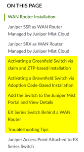
ge-0/0/3 - d4:20:b0:01:46:81 ETH0 d420b0014681The test above shows that the switch obtained a DHCP lease and should be able to initiate traffic with the Juniper Mist cloud to be managed. The remaining steps to onboard an EX Series Switch are explained in the JVD Distributed Branch EX Series. In the Day 1 section, review the sections shown in the figure below:
With the two downlinks configured on Spoke2 and a console cable attached to the switch, you can evaluate the following:
# ensure you ask for a new DHCP-Lease
root@switch1> restart dhcp-service
Junos Dynamic Host Configuration Protocol process started, pid 59162
#
# wait a few seconds
#
# review your routing table
root@switch1> show route
.
inet.0: 3 destinations, 3 routes (3 active, 0 holddown, 0 hidden)
Limit/Threshold: 32768/32768 destinations
+ = Active Route, - = Last Active, * = Both
.
0.0.0.0/0          *[Access-internal/12] 00:00:03, metric 0
                    >  to 10.33.33.1 via irb.0
10.33.33.0/24      *[Direct/0] 00:00:03
                    >  via irb.0
10.33.33.12/32     *[Local/0] 00:00:03
                       Local via irb.0
.
#
# review MAC-Table
root@switch1> show ethernet-switching table
MAC flags (S - static MAC, D - dynamic MAC, L - locally learned, P - Persistent static, C - Control MAC
           SE - statistics enabled, NM - non configured MAC, R - remote PE MAC, O - ovsdb MAC
           GBP - group based policy)
.
Ethernet switching table : 3 entries, 3 learned
Routing instance : default-switch
    Vlan                MAC                 MAC         Age   GBP     Logical                NH        RTR
    name                address             flags             Tag     interface              Index     ID
    default             90:ec:77:32:df:a5   D             -            ge-0/0/7.0             0         0
    default             d4:20:b0:01:46:bb   D             -            ge-0/0/3.0             0         0
#
# review  via ARP from WAN-Router received from an interface
MAC Address       Address         Interface                Flags
90:ec:77:32:df:a5 10.33.33.1      irb.0 [ge-0/0/7.0]       none
#
# confirm DNS and internet access
root@switch1> ping www.google.com inet
PING www.google.com (172.217.12.100): 56 data bytes
64 bytes from 172.217.12.100: icmp_seq=0 ttl=110 time=10.321 ms
64 bytes from 172.217.12.100: icmp_seq=1 ttl=110 time=16.570 ms
64 bytes from 172.217.12.100: icmp_seq=2 ttl=110 time=94.168 ms
^C
#
# review LLDP Neighbors
root@switch1> show lldp neighbors
Local Interface    Parent Interface    Chassis Id          Port info          System Name
ge-0/0/6           -                   90:ec:77:32:df:a5   ge-0-4             spoke2
ge-0/0/7           -                   90:ec:77:32:df:a6   ge-0-5             spoke2
ge-0/0/3           -                   d4:20:b0:01:46:bb   ETH0               d420b00146bb
#
# in this factory state there should not be yet any LACP configuration
root@switch1> show lacp interfaces
warning: lacp subsystem not running - not needed by configuration.
This section does not repeat the traffic topology tests, as the changes introduced are minimal. For detailed testing procedures, please refer to the Test Your Network Configuration section in the first topology.
Should you have this implemented then consider changing the spoke and hub LAN network configuration to no longer allow “Access to Mist Cloud” as we’ve done previously by default.