ON THIS PAGE
Example: Configuring a Collection of Paths to Create an RSVP-Signaled Point-to-Multipoint LSP
Configuring Primary and Branch LSPs for Point-to-Multipoint LSPs
Configuring a Multicast RPF Check Policy for Point-to-Multipoint LSPs
Configuring Ingress PE Router Redundancy for Point-to-Multipoint LSPs
Configuring a Service to Correlate Point-to-Multipoint sub-LSPs with FPCs
Preserving Point-to-Multipoint LSP Functioning with Different Junos OS Releases
Point-to-Multipoint LSP Configuration
Point-to-Multipoint LSPs Overview
A point-to-multipoint MPLS LSP is an LSP with a single source and multiple destinations. By taking advantage of the MPLS packet replication capability of the network, point-to-multipoint LSPs avoid unnecessary packet replication at the ingress router. Packet replication takes place only when packets are forwarded to two or more different destinations requiring different network paths.
This process is illustrated in Figure 1. Router PE1 is configured with a point-to-multipoint LSP to Routers PE2, PE3, and PE4. When Router PE1 sends a packet on the point-to-multipoint LSP to Routers P1 and P2, Router P1 replicates the packet and forwards it to Routers PE2 and PE3. Router P2 sends the packet to Router PE4.
This feature is described in detail in the Internet drafts draft-raggarwa-mpls-p2mp-te-02.txt (expired February 2004), Establishing Point to Multipoint MPLS TE LSPs, draft-ietf-mpls-rsvp-te-p2mp-02.txt, Extensions to Resource Reservation Protocol-Traffic Engineering (RSVP-TE) for Point-to-Multipoint TE Label-Switched Paths (LSPs), and RFC 6388, Label Distribution Protocol Extensions for Point-to-Multipoint and Multipoint-to-Multipoint Label Switched Paths (only point-to-multipoint LSPs are supported).
The following are some of the properties of point-to-multipoint LSPs:
A point-to-multipoint LSP enables you to use MPLS for point-to-multipoint data distribution. This functionality is similar to that provided by IP multicast.
You can add and remove branch LSPs from a main point-to-multipoint LSP without disrupting traffic. The unaffected parts of the point-to-multipoint LSP continue to function normally.
You can configure a node to be both a transit and an egress router for different branch LSPs of the same point-to-multipoint LSP.
You can enable link protection on a point-to-multipoint LSP. Link protection can provide a bypass LSP for each of the branch LSPs that make up the point-to-multipoint LSP. If any of the primary paths fail, traffic can be quickly switched to the bypass.
You can configure branch LSPs either statically, dynamically, or as a combination of static and dynamic LSPs.
You can enable graceful Routing Engine switchover (GRES) and graceful restart for point-to-multipoint LSPs at ingress and egress routers. The point-to-multipoint LSPs must be configured using either static routes or circuit cross-connect (CCC). GRES and graceful restart allow the traffic to be forwarded at the Packet Forwarding Engine based on the old state while the control plane recovers. Feature parity for GRES and graceful restart for MPLS point-to-multipoint LSPs on the Junos Trio chipset is supported in Junos OS Releases 11.1R2, 11.2R2, and 11.4.
Understanding Point-to-Multipoint LSPs
A point-to-multipoint MPLS label-switched path (LSP) is an LDP-signaled or RSVP-signaled LSP with a single source and multiple destinations. By taking advantage of the MPLS packet replication capability of the network, point-to-multipoint LSPs avoid unnecessary packet replication at the inbound (ingress) router. Packet replication takes place only when packets are forwarded to two or more different destinations requiring different network paths.
This process is illustrated in Figure 2. Device PE1 is configured with a point-to-multipoint LSP to Routers PE2, PE3, and PE4. When Device PE1 sends a packet on the point-to-multipoint LSP to Routers P1 and P2, Device P1 replicates the packet and forwards it to Routers PE2 and PE3. Device P2 sends the packet to Device PE4.

Following are some of the properties of point-to-multipoint LSPs:
A point-to-multipoint LSP allows you to use MPLS for point-to-multipoint data distribution. This functionality is similar to that provided by IP multicast.
You can add and remove branch LSPs from a main point-to-multipoint LSP without disrupting traffic. The unaffected parts of the point-to-multipoint LSP continue to function normally.
You can configure a node to be both a transit and an outbound (egress) router for different branch LSPs of the same point-to-multipoint LSP.
You can enable link protection on a point-to-multipoint LSP. Link protection can provide a bypass LSP for each of the branch LSPs that make up the point-to-multipoint LSP. If any primary paths fail, traffic can be quickly switched to the bypass.
You can configure subpaths either statically or dynamically.
You can enable graceful restart on point-to-multipoint LSPs.
Point-to-Multipoint LSP Configuration Overview
To set up a point-to-multipoint LSP:
- Configure the primary LSP from the ingress router and the branch LSPs that carry traffic to the egress routers.
- Specify a pathname on the primary LSP and this same path name on each branch LSP.
By default, the branch LSPs are dynamically signaled by means of Constrained Shortest Path First (CSPF) and require no configuration. You can alternatively configure the branch LSPs as static paths.
Example: Configuring a Collection of Paths to Create an RSVP-Signaled Point-to-Multipoint LSP
This example shows how to configure a collection of paths to create an RSVP-signaled point-to-multipoint label-switched path (LSP).
Requirements
In this example, no special configuration beyond device initialization is required.
Overview
In this example, multiple routing devices serve as the transit, branch, and leaf nodes of a single point-to-multipoint LSP. On the provider edge (PE), Device PE1 is the ingress node. The branches go from PE1 to PE2, PE1 to PE3, and PE1 to PE4. Static unicast routes on the ingress node (PE1) point to the egress nodes.
This example also demonstrates static routes with a next hop
that is a point-to-multipoint LSP, using the p2mp-lsp-next-hop statement. This is useful when implementing filter-based forwarding.
Another option is to use the lsp-next-hop statement to configure a regular point-to-point LSP to be the next
hop. Though not shown in this example, you can optionally assign an
independent preference and metric to the next hop.
Topology Diagram
Figure 3 shows the topology used in this example.
Configuration
- CLI Quick Configuration
- Configuring the Ingress Label-Switched Router (LSR) (Device PE1)
- Configuring the Transit and Egress LSRs (Devices P2, P3, P4, PE2, PE3, and PE4)
- Configuring Device CE1
- Configuring Device CE2
- Configuring Device CE3
- Configuring Device CE4
CLI Quick Configuration
To quickly configure this example, copy the
following commands, paste them into a text file, remove any line breaks,
change any details necessary to match your network configuration,
and then copy and paste the commands into the CLI at the [edit] hierarchy level.
Device PE1
set interfaces ge-2/0/2 unit 0 description PE1-to-CE1
set interfaces ge-2/0/2 unit 0 family inet address 10.0.244.10/30
set interfaces fe-2/0/10 unit 1 description PE1-to-P2
set interfaces fe-2/0/10 unit 1 family inet address 2.2.2.1/24
set interfaces fe-2/0/10 unit 1 family mpls
set interfaces fe-2/0/9 unit 8 description PE1-to-P3
set interfaces fe-2/0/9 unit 8 family inet address 6.6.6.1/24
set interfaces fe-2/0/9 unit 8 family mpls
set interfaces fe-2/0/8 unit 9 description PE1-to-P4
set interfaces fe-2/0/8 unit 9 family inet address 3.3.3.1/24
set interfaces fe-2/0/8 unit 9 family mpls
set interfaces lo0 unit 1 family inet address 100.10.10.10/32
set protocols rsvp interface fe-2/0/10.1
set protocols rsvp interface fe-2/0/9.8
set protocols rsvp interface fe-2/0/8.9
set protocols rsvp interface lo0.1
set protocols mpls traffic-engineering bgp-igp
set protocols mpls label-switched-path PE1-PE2 to 100.50.50.50
set protocols mpls label-switched-path PE1-PE2 link-protection
set protocols mpls label-switched-path PE1-PE2 p2mp p2mp1
set protocols mpls label-switched-path PE1-PE3 to 100.70.70.70
set protocols mpls label-switched-path PE1-PE3 link-protection
set protocols mpls label-switched-path PE1-PE3 p2mp p2mp1
set protocols mpls label-switched-path PE1-PE4 to 100.40.40.40
set protocols mpls label-switched-path PE1-PE4 link-protection
set protocols mpls label-switched-path PE1-PE4 p2mp p2mp1
set protocols mpls interface fe-2/0/10.1
set protocols mpls interface fe-2/0/9.8
set protocols mpls interface fe-2/0/8.9
set protocols mpls interface lo0.1
set protocols ospf traffic-engineering
set protocols ospf area 0.0.0.0 interface ge-2/0/2.0
set protocols ospf area 0.0.0.0 interface fe-2/0/10.1
set protocols ospf area 0.0.0.0 interface fe-2/0/9.8
set protocols ospf area 0.0.0.0 interface fe-2/0/8.9
set protocols ospf area 0.0.0.0 interface lo0.1
set routing-options static route 5.5.5.0/24 p2mp-lsp-next-hop p2mp1
set routing-options static route 7.7.7.0/24 p2mp-lsp-next-hop p2mp1
set routing-options static route 4.4.4.0/24 p2mp-lsp-next-hop p2mp1
set routing-options router-id 100.10.10.10
Device CE1
set interfaces ge-1/3/2 unit 0 family inet address 10.0.244.9/30
set interfaces ge-1/3/2 unit 0 description CE1-to-PE1
set routing-options static route 10.0.104.8/30 next-hop 10.0.244.10
set routing-options static route 10.0.134.8/30 next-hop 10.0.244.10
set routing-options static route 10.0.224.8/30 next-hop 10.0.244.10
Device CE2
set interfaces ge-1/3/3 unit 0 family inet address 10.0.224.9/30
set interfaces ge-1/3/3 unit 0 description CE2-to-PE2
set routing-options static route 10.0.244.8/30 next-hop 10.0.224.10
Device CE3
set interfaces ge-2/0/1 unit 0 family inet address 10.0.134.9/30
set interfaces ge-2/0/1 unit 0 description CE3-to-PE3
set routing-options static route 10.0.244.8/30 next-hop 10.0.134.10
Device CE4
set interfaces ge-3/1/3 unit 0 family inet address 10.0.104.10/30
set interfaces ge-3/1/3 unit 0 description CE4-to-PE4
set routing-options static route 10.0.244.8/30 next-hop 10.0.104.9
Configuring the Ingress Label-Switched Router (LSR) (Device PE1)
Step-by-Step Procedure
To configure Device PE1:
Configure the interfaces, interface encapsulation, and protocol families.
[edit interfaces]
user@PE1# set ge-2/0/2 unit 0 description PE1-to-CE1
user@PE1# set ge-2/0/2 unit 0 family inet address 10.0.244.10/30
user@PE1# set fe-2/0/10 unit 1 description PE1-to-P2
user@PE1# set fe-2/0/10 unit 1 family inet address 2.2.2.1/24
user@PE1# set fe-2/0/10 unit 1 family mpls
user@PE1# set fe-2/0/9 unit 8 description PE1-to-P3
user@PE1# set fe-2/0/9 unit 8 family inet address 6.6.6.1/24
user@PE1# set fe-2/0/9 unit 8 family mpls
user@PE1# set fe-2/0/8 unit 9 description PE1-to-P4
user@PE1# set fe-2/0/8 unit 9 family inet address 3.3.3.1/24
user@PE1# set fe-2/0/8 unit 9 family mpls
user@PE1# set lo0 unit 1 family inet address 100.10.10.10/32
Enable RSVP, MPLS, and OSPF on the interfaces.
[edit protocols]
user@PE1# set rsvp interface fe-2/0/10.1
user@PE1# set rsvp interface fe-2/0/9.8
user@PE1# set rsvp interface fe-2/0/8.9
user@PE1# set rsvp interface lo0.1
user@PE1# set mpls interface fe-2/0/10.1
user@PE1# set mpls interface fe-2/0/9.8
user@PE1# set mpls interface fe-2/0/8.9
user@PE1# set mpls interface lo0.1
user@PE1# set ospf area 0.0.0.0 interface ge-2/0/2.0
user@PE1# set ospf area 0.0.0.0 interface fe-2/0/10.1
user@PE1# set ospf area 0.0.0.0 interface fe-2/0/9.8
user@PE1# set ospf area 0.0.0.0 interface fe-2/0/8.9
user@PE1# set ospf area 0.0.0.0 interface lo0.1
Configure the MPLS point-to-multipoint LSPs.
[edit protocols]
user@PE1# set mpls label-switched-path PE1-PE2 to 100.50.50.50
user@PE1# set mpls label-switched-path PE1-PE2 p2mp p2mp1
user@PE1# set mpls label-switched-path PE1-PE3 to 100.70.70.70
user@PE1# set mpls label-switched-path PE1-PE3 p2mp p2mp1
user@PE1# set mpls label-switched-path PE1-PE4 to 100.40.40.40
user@PE1# set mpls label-switched-path PE1-PE4 p2mp p2mp1
(Optional) Enable link protection on the LSPs.
Link protection helps to ensure that traffic sent over a specific interface to a neighboring router can continue to reach the router if that interface fails.
[edit protocols]
user@PE1# set mpls label-switched-path PE1-PE2 link-protection
user@PE1# set mpls label-switched-path PE1-PE3 link-protection
user@PE1# set mpls label-switched-path PE1-PE4 link-protection
Enable MPLS to perform traffic engineering for OSPF.
[edit protocols]
user@PE1# set mpls traffic-engineering bgp-igp
This causes the ingress routes to be installed in the inet.0 routing table. By default, MPLS performs traffic engineering for BGP only. You need to enable MPLS traffic engineering on the ingress LSR only.
Enable traffic engineering for OSPF.
[edit protocols]
user@PE1# set ospf traffic-engineering
This causes the shortest-path first (SPF) algorithm to take into account the LSPs configured under MPLS.
Configure the router ID.
[edit routing-options]
user@PE1# set router-id 100.10.10.10
Configure static IP unicast routes with the point-to-multipoint LSP name as the next hop for each route.
[edit routing-options]
user@PE1# set static route 5.5.5.0/24p2mp-lsp-next-hop p2mp1
user@PE1# set static route 7.7.7.0/24 p2mp-lsp-next-hop p2mp1
user@PE1# set static route 4.4.4.0/24 p2mp-lsp-next-hop p2mp1
If you are done configuring the device, commit the configuration.
[edit]
user@PE1# commit
Configuring the Transit and Egress LSRs (Devices P2, P3, P4, PE2, PE3, and PE4)
Step-by-Step Procedure
To configure the transit and egress LSRs:
Configure the interfaces, interface encapsulation, and protocol families.
[edit]
user@P2# set interfaces fe-2/0/10 unit 2 description P2-to-PE1
user@P2# set interfaces fe-2/0/10 unit 2 family inet address 2.2.2.2/24
user@P2# set interfaces fe-2/0/10 unit 2 family mpls
user@P2# set interfaces fe-2/0/9 unit 10 description P2-to-PE2
user@P2# set interfaces fe-2/0/9 unit 10 family inet address 5.5.5.1/24
user@P2# set interfaces fe-2/0/9 unit 10 family mpls
user@P2# set interfaces lo0 unit 2 family inet address 100.20.20.20/32
user@PE2# set interfaces ge-2/0/3 unit 0 description PE2-to-CE2
user@PE2# set interfaces ge-2/0/3 unit 0 family inet address 10.0.224.10/30
user@PE2# set interfaces fe-2/0/10 unit 5 description PE2-to-P2
user@PE2# set interfaces fe-2/0/10 unit 5 family inet address 5.5.5.2/24
user@PE2# set interfaces fe-2/0/10 unit 5 family mpls
user@PE2# set interfaces lo0 unit 5 family inet address 100.50.50.50/32
user@P3# set interfaces fe-2/0/10 unit 6 description P3-to-PE1
user@P3# set interfaces fe-2/0/10 unit 6 family inet address 6.6.6.2/24
user@P3# set interfaces fe-2/0/10 unit 6 family mpls
user@P3# set interfaces fe-2/0/9 unit 11 description P3-to-PE3
user@P3# set interfaces fe-2/0/9 unit 11 family inet address 7.7.7.1/24
user@P3# set interfaces fe-2/0/9 unit 11 family mpls
user@P3# set interfaces lo0 unit 6 family inet address 100.60.60.60/32
user@PE3# set interfaces ge-2/0/1 unit 0 description PE3-to-CE3
user@PE3# set interfaces ge-2/0/1 unit 0 family inet address 10.0.134.10/30
user@PE3# set interfaces fe-2/0/10 unit 7 description PE3-to-P3
user@PE3# set interfaces fe-2/0/10 unit 7 family inet address 7.7.7.2/24
user@PE3# set interfaces fe-2/0/10 unit 7 family mpls
user@PE3# set interfaces lo0 unit 7 family inet address 100.70.70.70/32
user@P4# set interfaces fe-2/0/10 unit 3 description P4-to-PE1
user@P4# set interfaces fe-2/0/10 unit 3 family inet address 3.3.3.2/24
user@P4# set interfaces fe-2/0/10 unit 3 family mpls
user@P4# set interfaces fe-2/0/9 unit 12 description P4-to-PE4
user@P4# set interfaces fe-2/0/9 unit 12 family inet address 4.4.4.1/24
user@P4# set interfaces fe-2/0/9 unit 12 family mpls
user@P4# set interfaces lo0 unit 3 family inet address 100.30.30.30/32
user@PE4# set interfaces ge-2/0/0 unit 0 description PE4-to-CE4
user@PE4# set interfaces ge-2/0/0 unit 0 family inet address 10.0.104.9/30
user@PE4# set interfaces fe-2/0/10 unit 4 description PE4-to-P4
user@PE4# set interfaces fe-2/0/10 unit 4 family inet address 4.4.4.2/24
user@PE4# set interfaces fe-2/0/10 unit 4 family mpls
user@PE4# set interfaces lo0 unit 4 family inet address 100.40.40.40/32
Enable RSVP, MPLS, and OSPF on the interfaces.
[edit]
user@P2# set protocols rsvp interface fe-2/0/10.2
user@P2# set protocols rsvp interface fe-2/0/9.10
user@P2# set protocols rsvp interface lo0.2
user@P2# set protocols mpls interface fe-2/0/10.2
user@P2# set protocols mpls interface fe-2/0/9.10
user@P2# set protocols mpls interface lo0.2
user@P2# set protocols ospf area 0.0.0.0 interface fe-2/0/10.2
user@P2# set protocols ospf area 0.0.0.0 interface fe-2/0/9.10
user@P2# set protocols ospf area 0.0.0.0 interface lo0.2
user@PE2# set protocols rsvp interface fe-2/0/10.5
user@PE2# set protocols rsvp interface lo0.5
user@PE2# set protocols mpls interface fe-2/0/10.5
user@PE2# set protocols mpls interface lo0.5
user@PE2# set protocols ospf area 0.0.0.0 interface ge-2/0/3.0
user@PE2# set protocols ospf area 0.0.0.0 interface fe-2/0/10.5
user@PE2# set protocols ospf area 0.0.0.0 interface lo0.5
user@P3# set protocols rsvp interface fe-2/0/10.6
user@P3# set protocols rsvp interface fe-2/0/9.11
user@P3# set protocols rsvp interface lo0.6
user@P3# set protocols mpls interface fe-2/0/10.6
user@P3# set protocols mpls interface fe-2/0/9.11
user@P3# set protocols mpls interface lo0.6
user@P3# set protocols ospf area 0.0.0.0 interface fe-2/0/10.6
user@P3# set protocols ospf area 0.0.0.0 interface fe-2/0/9.11
user@P3# set protocols ospf area 0.0.0.0 interface lo0.6
user@PE3# set protocols rsvp interface fe-2/0/10.7
user@PE3# set protocols rsvp interface lo0.7
user@PE3# set protocols mpls interface fe-2/0/10.7
user@PE3# set protocols mpls interface lo0.7
user@PE3# set protocols ospf area 0.0.0.0 interface ge-2/0/1.0
user@PE3# set protocols ospf area 0.0.0.0 interface fe-2/0/10.7
user@PE3# set protocols ospf area 0.0.0.0 interface lo0.7
user@P4# set protocols rsvp interface fe-2/0/10.3
user@P4# set protocols rsvp interface fe-2/0/9.12
user@P4# set protocols rsvp interface lo0.3
user@P4# set protocols mpls interface fe-2/0/10.3
user@P4# set protocols mpls interface fe-2/0/9.12
user@P4# set protocols mpls interface lo0.3
user@P4# set protocols ospf area 0.0.0.0 interface fe-2/0/10.3
user@P4# set protocols ospf area 0.0.0.0 interface fe-2/0/9.12
user@P4# set protocols ospf area 0.0.0.0 interface lo0.3
user@PE4# set protocols rsvp interface fe-2/0/10.4
user@PE4# set protocols rsvp interface lo0.4
user@PE4# set protocols mpls interface fe-2/0/10.4
user@PE4# set protocols mpls interface lo0.4
user@PE4# set protocols ospf area 0.0.0.0 interface ge-2/0/0.0
user@PE4# set protocols ospf area 0.0.0.0 interface fe-2/0/10.4
user@PE4# set protocols ospf area 0.0.0.0 interface lo0.4
Enable traffic engineering for OSPF.
[edit]
user@P2# set protocols ospf traffic-engineering
user@P3# set protocols ospf traffic-engineering
user@P4# set protocols ospf traffic-engineering
user@PE2# set protocols ospf traffic-engineering
user@PE3# set protocols ospf traffic-engineering
user@PE4# set protocols ospf traffic-engineering
This causes the shortest-path first (SPF) algorithm to take into account the LSPs configured under MPLS.
Configure the router IDs.
[edit]
user@P2# set routing-options router-id 100.20.20.20
user@P3# set routing-options router-id 100.60.60.60
user@P4# set routing-options router-id 100.30.30.30
user@PE2# set routing-options router-id 100.50.50.50
user@PE3# set routing-options router-id 100.70.70.70
user@PE4# set routing-options router-id 100.40.40.40
If you are done configuring the devices, commit the configuration.
[edit]
user@host# commit
Results
From configuration mode, confirm your configuration
by entering the show interfaces, show protocols, and show routing-options commands. If the output does
not display the intended configuration, repeat the instructions in
this example to correct the configuration.
Device PE1
user@PE1# show interfaces
ge-2/0/2 {
    unit 0 {
        description R1-to-CE1;
        family inet {
            address 10.0.244.10/30;
        }
    }
}
fe-2/0/10 {
    unit 1 {
        description PE1-to-P2;
        family inet {
            address 2.2.2.1/24;
        }
        family mpls;
    }
}
fe-2/0/9 {
    unit 8 {
        description PE1-to-P2;
        family inet {
            address 6.6.6.1/24;
        }
        family mpls;
    }
}
fe-2/0/8 {
    unit 9 {
        description PE1-to-P3;
        family inet {
            address 3.3.3.1/24;
        }
        family mpls;
    }
}
lo0 {
    unit 1 {
        family inet {
            address 100.10.10.10/32;
        }
    }
}
user@PE1# show protocols
rsvp {
    interface fe-2/0/10.1;
    interface fe-2/0/9.8;
    interface fe-2/0/8.9;
    interface lo0.1;
}
mpls {
    traffic-engineering bgp-igp;
    label-switched-path PE1-to-PE2 {
        to 100.50.50.50;
        link-protection;
        p2mp p2mp1;
    }
    label-switched-path PE1-to-PE3 {
        to 100.70.70.70;
        link-protection;
        p2mp p2mp1;
    }
    label-switched-path PE1-to-PE4 {
        to 100.40.40.40;
        link-protection;
        p2mp p2mp1;
    }
    interface fe-2/0/10.1;
    interface fe-2/0/9.8;
    interface fe-2/0/8.9;
    interface lo0.1;
}
ospf {
    traffic-engineering;
    area 0.0.0.0 {
        interface ge-2/0/2.0;
        interface fe-2/0/10.1;
        interface fe-2/0/9.8;
        interface fe-2/0/8.9;
        interface lo0.1;
    }
}
user@PE1# show routing-options
static {
    route 5.5.5.0/24 {
        p2mp-lsp-next-hop p2mp1;
    }
    route 7.7.7.0/24 {
        p2mp-lsp-next-hop p2mp1;
    }
    route 4.4.4.0/24 {
        p2mp-lsp-next-hop p2mp1;
    }
}
router-id 100.10.10.10;
Device P2
user@P2# show interfaces
fe-2/0/10 {
    unit 2 {
        description P2-to-PE1;
        family inet {
            address 2.2.2.2/24;
        }
        family mpls;
    }
fe-2/0/9 {
    unit 10 {
        description P2-to-PE2;
        family inet {
            address 5.5.5.1/24;
        }
        family mpls;
    }
}
lo0 {
    unit 2 {
        family inet {
            address 100.20.20.20/32;
        }
    }
}
user@P2# show protocols
rsvp {
    interface fe-2/0/10.2;
    interface fe-2/0/9.10;
    interface lo0.2;
}
mpls {
    interface fe-2/0/10.2;
    interface fe-2/0/9.10;
    interface lo0.2;
}
ospf {
    traffic-engineering;
    area 0.0.0.0 {
        interface fe-2/0/10.2;
        interface fe-2/0/9.10;
        interface lo0.2;
    }
}
user@P2# show routing-options
router-id 100.20.20.20;
Device P3
user@P3# show interfaces
fe-2/0/10 {
    unit 6 {
        description P3-to-PE1;
        family inet {
            address 6.6.6.2/24;
        }
        family mpls;
    }
}
fe-2/0/9 {
    unit 11 {
        description P3-to-PE3;
        family inet {
            address 7.7.7.1/24;
        }
        family mpls;
    }
}
lo0 {
    unit 6 {
        family inet {
            address 100.60.60.60/32;
        }
    }
}
user@P3# show protocols
rsvp {
    interface fe-2/0/10.6;
    interface fe-2/0/9.11;
    interface lo0.6;
}
mpls {
    interface fe-2/0/10.6;
    interface fe-2/0/9.11;
    interface lo0.6;
}
ospf {
    traffic-engineering;
    area 0.0.0.0 {
        interface fe-2/0/10.6;
        interface fe-2/0/9.11;
        interface lo0.6;
    }
}
user@P2# show routing-options
router-id 100.60.60.60;
Device P4
user@P4# show interfaces
fe-2/0/10 {
    unit 3 {
        description P4-to-PE1;
        family inet {
            address 3.3.3.2/24;
        }
        family mpls;
    }
}
fe-2/0/9 {
    unit 12 {
        description P4-to-PE4;
        family inet {
            address 4.4.4.1/24;
        }
        family mpls;
    }
}
lo0 {
    unit 3 {
        family inet {
            address 100.30.30.30/32;
        }
    }
}
user@P4# show protocols
rsvp {
    interface fe-2/0/10.3;
    interface fe-2/0/9.12;
    interface lo0.3;
}
mpls {
    interface fe-2/0/10.3;
    interface fe-2/0/9.12;
    interface lo0.3;
}
ospf {
    traffic-engineering;
    area 0.0.0.0 {
        interface fe-2/0/10.3;
        interface fe-2/0/9.12;
        interface lo0.3;
    }
}
user@P3# show routing-options
router-id 100.30.30.30;
Device PE2
user@PE2# show interfaces
    ge-2/0/3 {
        unit 0 {
            description PE2-to-CE2;
            family inet {
                address 10.0.224.10/30;
            }
        }
    }
    fe-2/0/10 {
        unit 5 {
            description PE2-to-P2;
            family inet {
                address 5.5.5.2/24;
            }
            family mpls;
        }
    }
    lo0 {
        unit 5 {
            family inet {
                address 100.50.50.50/32;
            }
        }
    }
}
user@PE2# show protocols
rsvp {
    interface fe-2/0/10.5;
    interface lo0.5;
}
mpls {
    interface fe-2/0/10.5;
    interface lo0.5;
}
ospf {
    traffic-engineering;
    area 0.0.0.0 {
        interface ge-2/0/3.0;
        interface fe-2/0/10.5;
        interface lo0.5;
    }
}
user@PE2# show routing-options
router-id 100.50.50.50;
Device PE3
user@PE3# show interfaces
    ge-2/0/1 {
        unit 0 {
            description PE3-to-CE3;
            family inet {
                address 10.0.134.10/30;
            }
        }
    }
    fe-2/0/10 {
        unit 7 {
            description PE3-to-P3;
            family inet {
                address 7.7.7.2/24;
            }
            family mpls;
        }
    }
    lo0 {
        unit 7 {
            family inet {
                address 100.70.70.70/32;
            }
        }
    }
}
user@PE3# show protocols
rsvp {
    interface fe-2/0/10.7;
    interface lo0.7;
}
mpls {
    interface fe-2/0/10.7;
    interface lo0.7;
}
ospf {
    traffic-engineering;
    area 0.0.0.0 {
        interface ge-2/0/1.0;
        interface fe-2/0/10.7;
        interface lo0.7;
    }
}
user@PE3# show routing-options
router-id 100.70.70.70;
Device PE4
user@PE4# show interfaces
    ge-2/0/0 {
        unit 0 {
            description PE4-to-CE4;
            family inet {
                address 10.0.104.9/30;
            }
        }
    }
    fe-2/0/10 {
        unit 4 {
            description PE4-to-P4;
            family inet {
                address 4.4.4.2/24;
            }
            family mpls;
        }
    }
    lo0 {
        unit 4 {
            family inet {
                address 100.40.40.40/32;
            }
        }
    }
}
user@PE4# show protocols
rsvp {
    interface fe-2/0/10.4;
    interface lo0.4;
}
mpls {
    interface fe-2/0/10.4;
    interface lo0.4;
}
ospf {
    traffic-engineering;
    area 0.0.0.0 {
        interface ge-2/0/0.0;
        interface fe-2/0/10.4;
        interface lo0.4;
    }
}
user@PE4# show routing-options
router-id 100.40.40.40;
Configuring Device CE1
Step-by-Step Procedure
To configure Device CE1:
Configure an interface to Device PE1.
[edit interfaces]
user@CE1# set ge-1/3/2 unit 0 family inet address 10.0.244.9/30
user@CE1# set ge-1/3/2 unit 0 description CE1-to-PE1
Configure static routes from Device CE1 to the three other customer networks, with Device PE1 as the next hop.
[edit routing-options]
user@CE1# set static route 10.0.104.8/30 next-hop 10.0.244.10
user@CE1# set static route 10.0.134.8/30 next-hop 10.0.244.10
user@CE1# set static route 10.0.224.8/30 next-hop 10.0.244.10
If you are done configuring the device, commit the configuration.
[edit]
user@CE1# commit
Results
From configuration mode, confirm your configuration
by entering the show interfaces and show routing-options commands. If the output does not display the intended configuration,
repeat the instructions in this example to correct the configuration.
user@CE1# show interfaces
ge-1/3/2 {
    unit 0 {
        family inet {
            address 10.0.244.9/30;
            description CE1-to-PE1;
        }
    }
}
user@CE1# show routing-options
static {
    route 10.0.104.8/30 next-hop 10.0.244.10;
    route 10.0.134.8/30 next-hop 10.0.244.10;
    route 10.0.224.8/30 next-hop 10.0.244.10;
}
Configuring Device CE2
Step-by-Step Procedure
To configure Device CE2:
Configure an interface to Device PE2.
[edit interfaces]
user@CE2# set ge-1/3/3 unit 0 family inet address 10.0.224.9/30
user@CE2# set ge-1/3/3 unit 0 description CE2-to-PE2
Configure a static route from Device CE2 to CE1, with Device PE2 as the next hop.
[edit routing-options]
user@CE2# set static route 10.0.244.8/30 next-hop 10.0.224.10
If you are done configuring the device, commit the configuration.
[edit]
user@CE2# commit
Results
From configuration mode, confirm your configuration
by entering the show interfaces and show routing-options commands. If the output does not display the intended configuration,
repeat the instructions in this example to correct the configuration.
user@CE2# show interfaces
ge-1/3/3 {
    unit 0 {
        family inet {
            address 10.0.224.9/30;
            description CE2-to-PE2;
        }
    }
}
user@CE2# show routing-options
static {
    route 10.0.244.8/30 next-hop 10.0.224.10;
}
Configuring Device CE3
Step-by-Step Procedure
To configure Device CE3:
Configure an interface to Device PE3.
[edit interfaces]
user@CE3# set ge-2/0/1 unit 0 family inet address 10.0.134.9/30
user@CE3# set ge-2/0/1 unit 0 description CE3-to-PE3
Configure a static route from Device CE3 to CE1, with Device PE3 as the next hop.
[edit routing-options]
user@CE3# set static route 10.0.244.8/30 next-hop 10.0.134.10
If you are done configuring the device, commit the configuration.
[edit]
user@CE3# commit
Results
From configuration mode, confirm your configuration
by entering the show interfaces and show routing-options commands. If the output does not display the intended configuration,
repeat the instructions in this example to correct the configuration.
user@CE3# show interfaces
ge-2/0/1 {
    unit 0 {
        family inet {
            address 10.0.134.9/30;
            description CE3-to-PE3;
        }
    }
}
user@CE3# show routing-options
static {
    route 10.0.244.8/30 next-hop 10.0.134.10;
}
Configuring Device CE4
Step-by-Step Procedure
To configure Device CE4:
Configure an interface to Device PE4.
[edit interfaces]
user@CE4# set ge-3/1/3 unit 0 family inet address 10.0.104.10/30
user@CE4# set ge-3/1/3 unit 0 description CE4-to-PE4
Configure a static route from Device CE4 to CE1, with Device PE4 as the next hop.
[edit routing-options]
user@CE4# set static route 10.0.244.8/30 next-hop 10.0.104.9
If you are done configuring the device, commit the configuration.
[edit]
user@CE4# commit
Results
From configuration mode, confirm your configuration
by entering the show interfaces and show routing-options commands. If the output does not display the intended configuration,
repeat the instructions in this example to correct the configuration.
user@CE4# show interfaces
ge-3/1/3 {
    unit 0 {
        family inet {
            address 10.0.104.10/30;
            description CE4-to-PE4;
        }
    }
}
user@CE4# show routing-options
static {
    route 10.0.244.8/30 next-hop 10.0.104.9;
}
Verification
Confirm that the configuration is working properly.
- Verifying Connectivity
- Verifying the State of the Point-to-Multipoint LSP
- Checking the Forwarding Table
Verifying Connectivity
Purpose
Make sure that the devices can ping each other.
Action
Run the ping command from CE1 to the interface
on CE2 connecting to PE2.
user@CE1> ping 10.0.224.9
PING 10.0.224.9 (10.0.224.9): 56 data bytes
64 bytes from 10.0.224.9: icmp_seq=0 ttl=61 time=1.387 ms
64 bytes from 10.0.224.9: icmp_seq=1 ttl=61 time=1.394 ms
64 bytes from 10.0.224.9: icmp_seq=2 ttl=61 time=1.506 ms
^C
--- 10.0.224.9 ping statistics ---
3 packets transmitted, 3 packets received, 0% packet loss
round-trip min/avg/max/stddev = 1.387/1.429/1.506/0.055 ms
Run the ping command from CE1 to the interface
on CE3 connecting to PE3.
user@CE1> ping 10.0.134.9
PING 10.0.134.9 (10.0.134.9): 56 data bytes
64 bytes from 10.0.134.9: icmp_seq=0 ttl=61 time=1.068 ms
64 bytes from 10.0.134.9: icmp_seq=1 ttl=61 time=1.062 ms
64 bytes from 10.0.134.9: icmp_seq=2 ttl=61 time=1.053 ms
^C
--- 10.0.134.9 ping statistics ---
3 packets transmitted, 3 packets received, 0% packet loss
round-trip min/avg/max/stddev = 1.053/1.061/1.068/0.006 ms
Run the ping command from CE1 to the interface
on CE4 connecting to PE4.
user@CE1> ping 10.0.104.10
PING 10.0.104.10 (10.0.104.10): 56 data bytes
64 bytes from 10.0.104.10: icmp_seq=0 ttl=61 time=1.079 ms
64 bytes from 10.0.104.10: icmp_seq=1 ttl=61 time=1.048 ms
64 bytes from 10.0.104.10: icmp_seq=2 ttl=61 time=1.070 ms
^C
--- 10.0.104.10 ping statistics ---
3 packets transmitted, 3 packets received, 0% packet loss
round-trip min/avg/max/stddev = 1.048/1.066/1.079/0.013 ms
Verifying the State of the Point-to-Multipoint LSP
Purpose
Make sure that the ingress, transit, and egress LSRs are in the Up state.
Action
Run the show mpls lsp p2mp command on all of the LSRs. Only the ingress LSR is shown
here.
user@PE1> show mpls lsp p2mp
Ingress LSP: 1 sessions
P2MP name: p2mp1, P2MP branch count: 3
To              From            State Rt P     ActivePath       LSPname
100.40.40.40    100.10.10.10    Up     0 *                      PE1-PE4
100.70.70.70    100.10.10.10    Up     0 *                      PE1-PE3
100.50.50.50    100.10.10.10    Up     0 *                      PE1-PE2
Total 3 displayed, Up 3, Down 0
...
Checking the Forwarding Table
Purpose
Make sure that the routes are set up as expected by
running the show route forwarding-table command. Only the routes to the remote customer networks are
shown here.
Action
user@PE1> show route forwarding-table
Routing table: default.inet
Internet:
Destination        Type RtRef Next hop           Type Index NhRef Netif
...
10.0.104.8/30      user     0 3.3.3.2            ucst  1006     6 fe-2/0/8.9
10.0.134.8/30      user     0 6.6.6.2            ucst  1010     6 fe-2/0/9.8
10.0.224.8/30      user     0 2.2.2.2            ucst  1008     6 fe-2/0/10.1
...
Configuring Primary and Branch LSPs for Point-to-Multipoint LSPs
A point-to-multipoint MPLS label-switched path (LSP) is an RSVP LSP with multiple destinations. By taking advantage of the MPLS packet replication capability of the network, point-to-multipoint LSPs avoid unnecessary packet replication at the ingress router. For more information about point-to-multipoint LSPs, see Point-to-Multipoint LSPs Overview.
To configure a point-to-multipoint LSP, you need to configure the primary LSP from the ingress router and the branch LSPs that carry traffic to the egress routers, as described in the following sections:
- Configuring the Primary Point-to-Multipoint LSP
- Configuring a Branch LSP for Point-to-Multipoint LSPs
Configuring the Primary Point-to-Multipoint LSP
A point-to-multipoint LSP must have a configured primary point-to-multipoint
LSP to carry traffic from the ingress router. The configuration of
the primary point-to-multipoint LSP is similar to a signaled LSP.
See Configuring the Ingress Router for
MPLS-Signaled LSPs for more information. In addition to
the conventional LSP configuration, you need to specify a path name
for the primary point-to-multipoint LSP by including the p2mp statement:
p2mp p2mp-lsp-name;
You can include this statement at the following hierarchy levels:
[edit protocols mpls label-switched-path lsp-name][edit logical-systems logical-system-name protocols mpls label-switched-path lsp-name]
You can enable the optimization timer for point-to-multipoint LSPs. See Optimizing Signaled LSPs for more information.
Configuring a Branch LSP for Point-to-Multipoint LSPs
The primary point-to-multipoint LSP sends traffic to two or more branch LSPs carrying traffic to each of the egress provider edge (PE) routers. In the configuration for each of these branch LSPs, the point-to-multipoint LSP path name you specify must be identical to the path name configured for the primary point-to-multipoint LSP. See Configuring the Primary Point-to-Multipoint LSP for more information.
To associate a branch LSP with the primary point-to-multipoint
LSP, specify the point-to-multipoint LSP name by including the p2mp statement:
p2mp p2mp-lsp-name;
You can include this statement at the following hierarchy levels:
[edit protocols mpls label-switched-path lsp-name][edit logical-systems logical-system-name protocols mpls label-switched-path lsp-name]Note:Any change in any of the branch LSPs of a point-to-multipoint LSP, either due to a user action or an automatic adjustment made by the router, causes the primary and branch LSPs to be resignaled. The new point-to-multipoint LSP is signaled first before the old path is taken down.
The following sections describe how you can configure the branch LSP as a dynamically signaled path using Constrained Shortest Path First (CSPF), as a static path, or as a combination of dynamic and static paths:
Configuring the Branch LSP as a Dynamic Path
By default, the branch LSP for a point-to-multipoint LSP is signaled dynamically using CSPF and requires no configuration.
When a point-to-multipoint LSP is changed, either by the addition or deletion of new destinations or by the recalculation of the path to existing destinations, certain nodes in the tree might receive data from more than one incoming interface. This can happen under the following conditions:
Some of the branch LSPs to destinations are statically configured and might intersect with statically or dynamically calculated paths to other destinations.
When a dynamically calculated path for a branch LSP results in a change of incoming interface for one of the nodes in the network, the older path is not immediately torn down after the new one has been signaled. This ensures that any data in transit relying on the older path can reach its destination. However, network traffic can potentially use either path to reach the destination.
A faulty router at the ingress calculates the paths to two different branch destinations such that a different incoming interface is chosen for these branch LSPs on a router node common to these branch LSPs.
Configuring the Branch LSP as a Static Path
You can configure the branch LSP for a point-to-multipoint LSP as a static path. See Configuring Static LSPs for more information.
Configuring Inter-Domain Point-to-Multipoint LSPs
An inter-domain P2MP LSP is a P2MP LSP that has one or more sub-LSPs (branches) that span multiple domains in a network. Examples of such domains include IGP areas and autonomous systems (ASs). A sub-LSP of an inter-domain P2MP LSP may be intra-area, inter-area, or inter-AS, depending on the location of the egress node (leaf) with respect to the ingress node (source).
On the ingress node, a name is assigned to the inter-domain P2MP LSP and shared by all constituent sub-LSPs. Each sub-LSP is configured separately, with its own egress node and optionally an explicit path. The location of the egress node of the sub-LSP with respect to the ingress node determines whether the sub-LSP is intra-area, inter-area, or inter-AS.
Inter-domain P2MP LSPs can be used to transport traffic in the following applications in a multi-area or multi-AS network:
Layer 2 broadcast and multicast over MPLS
Layer 3 BGP/MPLS VPN
VPLS
On each domain boundary node (ABR or ASBR) along the path of
the P2MP LSP, the expand-loose-hop statement must be configured
at the [edit protocols mpls] hierarchy level so that CSPF
can extend a loose-hop ERO (usually the first entry of the ERO list
carried by RSVP Path message) towards the egress node or the next
domain boundary node.
CSPF path computation for inter-domain P2MP LSPs:
CSPF path computation is supported on each sub-LSP for inter-domain P2MP LSPs. A sub-LSP may be intra-area, inter-area, or inter-AS. CSPF treats an inter-area or inter-AS sub-LSP in the same manner as an inter-domain P2P LSP.
On an ingress node or a domain boundary node (ABR or ASBR), CSPF can perform an Explicit Route Object (ERO) expansion per-RSVP query. The destination queried could be an egress node or a received loose-hop ERO. If the destination resides in a neighboring domain that the node is connected to, CSPF generates either a sequence of strict-hop EROs towards it or a sequence of strict-hop EROs towards another domain boundary node that can reach the destination.
If RSVP fails to signal a path through a previously selected domain bounday node, RSVP attempts to signal a path through other available domain boundary nodes in a round-robin fashion.
When a sub-LSP is added or removed to or from an inter-domain P2MP LSP, causing its path (branch) to be merged or pruned with or from the current P2MP tree, the paths being taken by the other sub-LSPs should not be affected, helping to prevent traffic disruption on those sub-LSPs.
Be aware of the following when deploying inter-domain P2MP LSPs in your network:
Periodic path re-optimization is supported for inter-domain P2MP LSPs on ingress nodes. It can be turned on for an inter-domain P2MP LSP by configuring the
optimize-timerstatement at the[edit protocols mpls label-switched-path lsp-name]hierarchy level with the same interval for every sub-LSP.Only link protection bypass LSPs are supported for inter-domain P2MP LSPs. To enable it for an inter-domain P2MP LSP, link-protection must be configured for all sub-LSPs and on all of the RSVP interfaces that the P2MP LSP might travel through.
Only OSPF areas are supported for inter-domain P2MP LSPs. IS-IS levels are not supported.
Configuring Link Protection for Point-to-Multipoint LSPs
Link protection helps to ensure that traffic going over a specific interface to a neighboring router can continue to reach this router if that interface fails. When link protection is configured for an interface and a point-to-multipoint LSP that traverses this interface, a bypass LSP is created that handles this traffic if the interface fails. The bypass LSP uses a different interface and path to reach the same destination.
To extend link protection to all of the paths used by a point-to-multipoint LSP, link protection must be configured on each router that each branch LSP traverses. If you enable link protection on a point-to-multipoint LSP, you must enable link protection on all of the branch LSPs.
The Internet draft draft-ietf-mpls-rsvp-te-p2mp-01.txt, Extensions to RSVP-TE for Point to Multipoint TE LSPs, describes link protection for point-to-multipoint LSPs.
To enable link protection on point-to-multipoint LSPs, complete the following steps:
Configure link protection on each branch LSP. To configure link protection, include the
link-protectionstatement:link-protection;
You can include this statement at the following hierarchy levels:
[edit protocols mpls label-switched-path branch-lsp-name][edit logical-systems logical-system-name protocols mpls label-switched-path branch-lsp-name]
Configure link protection for each RSVP interface on each router that the branch LSP traverses. For information about how to configure link protection on RSVP interfaces, see Configuring Link Protection on Interfaces Used by LSPs.
For more information on how to configure link protection, see Configuring Node Protection or Link Protection for LSPs.
Configuring Graceful Restart for Point-to-Multipoint LSPs
You can configure graceful restart on point-to-multipoint LSPs. Graceful restart allows a router undergoing a restart to inform its adjacent neighbors of its condition. The restarting router requests a grace period from the neighbor or peer, which can then cooperate with the restarting router. The restarting router can still forward MPLS traffic during the restart period; convergence in the network is not disrupted. The restart is not apparent to the rest of the network, and the restarting router is not removed from the network topology. RSVP graceful restart can be enabled on both transit routers and ingress routers.
To enable graceful restart on a router handling point-to-multipoint
LSP traffic, include the graceful-restart statement:
graceful-restart;
You can include this statement at the following hierarchy levels:
[edit routing-options][edit logical-systems logical-system-name routing-options]
The graceful restart configuration for point-to-multipoint LSPs is identical to that of point-to-point LSPs. For more information on how to configure graceful restart, see Configuring RSVP Graceful Restart.
Configuring a Multicast RPF Check Policy for Point-to-Multipoint LSPs
You can control whether a reverse path forwarding (RPF) check is performed for a source and group entry before installing a route in the multicast forwarding cache. This makes it possible to use point-to-multipoint LSPs to distribute multicast traffic to PIM islands situated downstream from the egress routers of the point-to-multipoint LSPs.
By configuring the rpf-check-policy statement, you
can disable RPF checks for a source and group pair. You would typically
configure this statement on the egress routers of a point-to-multipoint
LSP, because the interface receiving the multicast traffic on a point-to-multipoint
LSP egress router might not always be the RPF interface.
You can also configure a routing policy to act upon a source and group pair. This policy behaves like an import policy, so if no policy term matches the input data, the default policy action is “acceptance.” An accept policy action enables RPF checks. A reject policy action (applied to all source and group pairs that are not accepted) disables RPF checks for the pair.
To configure a multicast RPF check policy for a point-to-multipoint
LSP, specify the RPF check policy using the rpf-check-policy statement:
rpf-check-policy policy;
You can include this statement at the following hierarchy levels:
[edit routing-options multicast][edit logical-systems logical-system-name routing-options multicast]
You also must configure a policy for the multicast RPF check.
You configure policies at the [edit policy-options] hierarchy
level. For more information, see the Routing Policies, Firewall Filters, and Traffic Policers User Guide.
When you configure the rpf-check-policy statement,
the Junos OS cannot perform RPF checks on incoming traffic and therefore
cannot detect traffic arriving on the wrong interface. This might
cause routing loops to form.
Example: Configuring Multicast RPF Check Policy for a Point-to-Multipoint LSP
Configure a policy to ensure that an RPF check is not performed
for sources with prefix 128.83/16 or longer that belong
to groups having a prefix of 228/8 or longer:
[edit]
policy-options {
    policy-statement rpf-sg-policy {
        from {
            route-filter 228.0.0.0/8 orlonger;
            source-address-filter 128.83.0.0/16 orlonger;
        }
        then {
            reject;
        }
    }
}
Configuring Ingress PE Router Redundancy for Point-to-Multipoint LSPs
You can configure one or more PE routers as part of a backup PE router group to enable ingress PE router redundancy. You accomplish this by configuring the IP addresses of the backup PE routers (at least one backup PE router is required) and the local IP address used by the local PE router.
You must also configure a full mesh of point-to-point LSPs between the primary and backup PE routers. You also need to configure BFD on these LSPs. See Configuring BFD for RSVP-Signaled LSPs and Configuring BFD for LDP LSPs for more information.
To configure ingress PE router redundancy for point-to-multipoint
LSPs, include the backup-pe-group statement:
backup-pe-group pe-group-name {
    backups [addresses];
    local-address address;
}
For a list of hierarchy levels at which you can include these statements, see the statement summary sections for these statements.
After you configure the ingress PE router redundancy backup
group, you must also apply the group to a static route on the PE router.
This ensures that the static route is active (installed in the forwarding
table) when the local PE router is the designated forwarder for the
backup PE group. You can only associate a backup PE router group with
a static route that also has the p2mp-lsp-next-hop statement
configured. For more information, see Configuring Static Unicast Routes for Point-to-Multipoint
LSPs.
Configuring a Service to Correlate Point-to-Multipoint sub-LSPs with FPCs
In addition to acting as the ingress or egress for a given sub-LSP, the Packet Forwarding Engine on an FPC also serves as a transit point for other sub-LSPs of the same point-to-multipoint LSP. If an FPC fails, then all the sub-LSPs that it serves are affected.
You can configure a service that enables you to monitor the correlation between FPCs and the point-to-multipoint sub-LSPs—branch paths—that are on an LSR. This information helps you evaluate the effect a failed FPC has on the correlated sub-LSPs. When tracing is enabled, the service also provides syslog messages in the event of an FPC outage that provide detailed information about the sub-LSPs affected.
You can configure a service that enables you to monitor the correlation between FPCs and the point-to-multipoint sub-LSPs—branch paths—on an LSR. An FPC can act as an ingress, egress, or transit point for more than one sub-LSP of the same point-to-multipoint LSP. If an FPC fails, then all the sub-LSPs that it serves are affected.
The information provided by this service helps you evaluate the effect a failure in any FPC has on the correlated sub-LSPs and the point-to-multipoint network. You can use this knowledge to help plan controlled FPC outages.
You can also enable tracing of some or all service operations. The service then provides syslog messages with detailed information about the affected sub-LSPs that facilitates analysis of an FPC outage.
To enable the monitoring and correlation of sub-LSPs and FPCs in the point-to-multipoint network:
- Configure the point-to-multipoint polling (
p2mp_polling_duration) and FPC polling (fpc_polling_duration) by setting the frequency duration (in seconds) in the config.xml file located at the /etc/p2mp_lsp_correlation directory. You can also enable log levels in the config.xml file to configure traceoptions and the logs are created at the /var/log/p2mp_lsp_correlation directory. The log level and message types are as follows:5 = DEBUG 4 = INFO 3 = WARNING 2 = ERROR 1 = CRITICAL
The following is a sample config.xml file:
user@host:~# cat /etc/p2mp_lsp_correlation/config.xml <p2mp_sub_lsp_config> <p2mp_polling_duration>240</p2mp_polling_duration> <fpc_polling_duration>60</fpc_polling_duration> <log_level>5</log_level> </p2mp_sub_lsp_config>p2mp_polling_duration–Refreshes the database by executing various RE/PFE RPC requests. The default value for point-to-multipoint polling duration is 240.fpc_polling_duration–Polls for status of the FPC/PFE to log the impact of point-to-multipoint sub-LSPs. The default for FPC polling duration is 60.
Note:The config.xml file is applicable only for Junos OS Evolved. You need to restart the application after making changes to the config.xml file.
- Enable the
service.
[edit services]
user@host# set p2mp-sublsp-correlation
- Configure tracing of the service operations.
[edit services]
user@host# set p2mp-sublsp-correlation traceoptions flag all
Note:The
set p2mp-sublsp-correlation traceoptions flag allcommand is not applicable for Junos OS Evolved.
When an FPC on an LSR fails or goes offline, all point-to-multipoint sub-LSPs on that FPC are affected. If you have previously enabled FPC correlation for the point-to-multipoint LSPs, and configured tracing for the correlation service, then upon FPC failure messages are logged that provide details about the affected sub-LSPs.
In this case, you need to examine the system log messages and the FPC correlation table to analyze the impact of an FPC failure.
The following is a sample system log output showing information about the point-to-multipoint sub-LSP when the impacted FPC goes offline:
Aug  5 12:47:33  host mdiag[24321]: MDIAGD_P2MP_SUBLSP_IMPACTED: FPC 0
    PFEInst 0 Role (I,E,T) DOWN P2MP-Tunnel-Name p2mp-2-456 Sub-LSP-Dest 4.4.4.4 Sub-LSP-
    Name lsp-2-4 Tunnel-ID 53322 LSP-ID 1 Src-Addr 2.2.2.2 Sub-Group-ID 10 Ingress-
    Interface ae8.0 Egress-Interface et-0/0/7.0
To view the point-to-multipoint sub-LSP correlation information for ingress interface, use
the show services p2mp-sublsp-correlation ingress-interface command as
follows:
user@host> show services p2mp-sublsp-correlation ingress-interface ae8.0
Last Refreshed : Aug 05 2021 12:06:50

SG-ID = Sub-Group-ID, Tun-ID =  Tunnel-ID
FPC ROLE: I = Ingress, E = Egress, T = Transit

P2MP  Sub-LSP  Sub-LSP  Tun   LSP  Source   SG  Ingress  Egress
Name   Dest    Name     ID     ID  Address  ID  Interface Interface

bud-p-68 8.8.8.8  bud-8  53323  1  2.2.2.2  18  ae8.0     et-0/0/5.0
bud-p-68 6.6.6.6  bud-6  53323  1  2.2.2.2  12  ae8.0     et-0/0/9.0
bud-p-68 7.7.7.7  bud-7  53323  1  2.2.2.2  17  ae8.0     et-0/0/7.0
p2mp-2-6 4.4.4.4  lsp-4  53322  1  2.2.2.2  10  ae8.0     et-0/0/7.0
p2mp-2-6 5.5.5.5  lsp-5  53322  1  2.2.2.2  15  ae8.0     et-0/0/5.0
p2mp-2-6 6.6.6.6  lsp-6  53322  1  2.2.2.2  12  ae8.0     et-0/0/9.0
To view the point-to-multipoint sub-LSP correlation information for egress interface, use the
show services p2mp-sublsp-correlation egress-interface command as
follows:
user@host> show services p2mp-sublsp-correlation egress-interface et-0/0/7.0
Last Refreshed : Aug 05 2021 12:06:50

SG-ID = Sub-Group-ID, Tun-ID =  Tunnel-ID
FPC ROLE: I = Ingress, E = Egress, T = Transit

P2MP  Sub-LSP  Sub-LSP  Tun   LSP  Source   SG  Ingress  Egress
Name   Dest    Name     ID     ID  Address  ID  Interface Interface

bud-p-68 7.7.7.7  bud-7  53323  1  2.2.2.2  17  ae8.0     et-0/0/7.0
p2mp-2-6 4.4.4.4  lsp-4  53322  1  2.2.2.2  10  ae8.0     et-0/0/7.0
To view the correlation information for FPC, use the show services
p2mp-sublsp-correlation fpc 0 command as follows:
user@host> show services p2mp-sublsp-correlation fpc 0
Last Refreshed : Aug 05 2021 12:06:50

SG-ID = Sub-Group-ID, Tun-ID =  Tunnel-ID
FPC ROLE: I = Ingress, E = Egress, T = Transit

P2MP  Sub-LSP  Sub-LSP  Tun   LSP  Source   SG  Ingress  Egress    FPC/PFE
Name   Dest    Name     ID     ID  Address  ID  Interface Interface   Role

bud-p-68 8.8.8.8  bud-8  53323  1  2.2.2.2  18  ae8.0     et-0/0/5.0  I,E,
bud-p-68 6.6.6.6  bud-6  53323  1  2.2.2.2  12  ae8.0     et-0/0/9.0  I,E,T
bud-p-68 7.7.7.7  bud-7  53323  1  2.2.2.2  17  ae8.0     et-0/0/7.0  I,E,
p2mp-2-6 4.4.4.4  lsp-4  53322  1  2.2.2.2  10  ae8.0     et-0/0/7.0  I,E,T
p2mp-2-6 5.5.5.5  lsp-5  53322  1  2.2.2.2  15  ae8.0     et-0/0/5.0  I,E,T
p2mp-2-6 6.6.6.6  lsp-6  53322  1  2.2.2.2  12  ae8.0     et-0/0/9.0  I,E,
To view the correlation information for PFE instance, use the show services
p2mp-sublsp-correlation fpc 0 pfe-instance 0 command as follows:
user@host> show services p2mp-sublsp-correlation fpc 0 pfe-instance 0
Last Refreshed : Aug 05 2021 12:06:50

SG-ID = Sub-Group-ID, Tun-ID =  Tunnel-ID
FPC ROLE: I = Ingress, E = Egress, T = Transit

P2MP  Sub-LSP  Sub-LSP  Tun   LSP  Source   SG  Ingress  Egress    FPC/PFE
Name   Dest    Name     ID     ID  Address  ID  Interface Interface   Role

bud-p-68 8.8.8.8  bud-8  53323  1  2.2.2.2  18  ae8.0     et-0/0/5.0  I,E,
bud-p-68 6.6.6.6  bud-6  53323  1  2.2.2.2  12  ae8.0     et-0/0/9.0  I,E,T
bud-p-68 7.7.7.7  bud-7  53323  1  2.2.2.2  17  ae8.0     et-0/0/7.0  I,E,
p2mp-2-6 4.4.4.4  lsp-4  53322  1  2.2.2.2  10  ae8.0     et-0/0/7.0  I,E,T
p2mp-2-6 5.5.5.5  lsp-5  53322  1  2.2.2.2  15  ae8.0     et-0/0/5.0  I,E,T
p2mp-2-6 6.6.6.6  lsp-6  53322  1  2.2.2.2  12  ae8.0     et-0/0/9.0  I,E,
Enabling Point-to-Point LSPs to Monitor Egress PE Routers
Configuring an LSP with the associate-backup-pe-groups statement enables it to monitor the status of the PE router to which
it is configured. You can configure multiple backup PE router groups
using the same router's address. A failure of this LSP indicates to
all of the backup PE router groups that the destination PE router
is down. The associate-backup-pe-groups statement is not
tied to a specific backup PE router group. It applies to all groups
that are interested in the status of the LSP to that address.
To allow an LSP to monitor the status of the egress PE router,
include the associate-backup-pe-groups statement:
associate-backup-pe-groups;
This statement can be configured at the following hierarchy levels:
[edit protocols mpls label-switched-path lsp-name][edit logical-systems logical-system-name protocols mpls label-switched-path lsp-name]
If you configure the associate-backup-pe-groups statement,
you must configure BFD for the point-to-point LSP. For information
about how to configure BFD for an LSP, see Configuring BFD for MPLS IPv4 LSPs and Configuring
BFD for LDP LSPs.
You also must configure a full mesh of point-to-point LSPs between the PE routers in the backup PE router group. A full mesh is required so that each PE router within the group can independently determine the status of the other PE routers, allowing each router to independently determine which PE router is currently the designated forwarder for the backup PE router group.
If you configure multiple LSPs with the associate-backup-pe-groups statement to the same destination PE router, the first LSP configured
is used to monitor the forwarding state to that PE router. If you
configure multiple LSPs to the same destination, make sure to configure
similar parameters for the LSPs. With this configuration scenario,
a failure notification might be triggered even though the remote PE
router is still up.
Preserving Point-to-Multipoint LSP Functioning with Different Junos OS Releases
In Junos OS Release 9.1 and earlier, Resv messages
that include the S2L_SUB_LSP object are rejected by default. In Junos
OS Release 9.2 and later, such messages are accepted by default.
To ensure proper functioning of point-to-multipoint LSPs in a network
that includes both devices running Junos OS Release 9.1 and earlier
and devices running Junos 9.2 and later, you must include the no-p2mp-sublsp statement in the configuration of the devices
running Junos 9.2 and later:
no-p2mp-sublsp;
You can include this statement at the following hierarchy levels:
[edit protocols rsvp][edit logical-systems logical-system-name protocols rsvp]
Re-merge Behavior on Point-to-Multipoint LSP Overview
This section talks about the benefits and overview of controlling the re-merge behavior on RSVP Point-to-Multipoint (P2MP) LSPs.
- Benefits of Controlling the P2MP LSP Re-merge
- What is P2MP LSP Re-merge?
- Modify the Default P2MP LSP Re-merge Behavior
Benefits of Controlling the P2MP LSP Re-merge
Reduces the RSVP signalling load on the ingress (headend routers) by avoiding path computation of sub LSPs which creates a re-merge condition.
Saves the network bandwidth by rejecting the P2MP sub LSP re-merge at the transit node.
What is P2MP LSP Re-merge?
In a P2MP MPLS LSP network, the term re-merge refers to the case of an ingress (headend) or transit node (re-merge node) that creates a re-merge branch intersecting the P2MP LSP at another node down the tree. This may occur due to events such as an error in path calculation, an error in manual configuration, or network topology changes during the establishment of the P2MP LSP.
RFC 4875 defines the following two approaches for handling the P2MP LSP re-merge:
First, the node detecting the re-merge allows the re-merge case to persist, but data from all but one incoming interface is dropped at the re-merge node. This works by default without any configuration.
Second, the re-merge node initiates the pruning of the re-merge sub LSPs through signaling.
On Juniper Networks MX Series routers, the first approach (as defined by RFC 4875) works by default. The second approach can be implemented by one of the following CLI configuration statements depending upon where the Juniper Networks MX Series routers are placed (ingress node or transit node) in the P2MP RSVP MPLS network:
no-re-merge—This CLI configuration statement when enabled at the ingress (headend) router avoids the path computation of P2MP sub LSPs which creates a re-merge condition. When this CLI configuration statement is configured at the ingress, then configuring theno-p2mp-re-mergeCLI configuration statement at the transit router is not required.no-p2mp-re-merge—This CLI configuration statement when enabled at the transit router changes the default behavior of allowing the P2MP sub LSP sessions re-merge to rejecting the re-merge. This CLI configuration statement is primarily required when the ingress (headend router) is not a Juniper Networks MX Series router.single-abr—This command when enabled reduces re-merge condition beyond the inter-area, or inter-domain, or inter-AS RSVP P2MP LSPs.
The following topology explains the re-merge behavior in a P2MP LSP network:
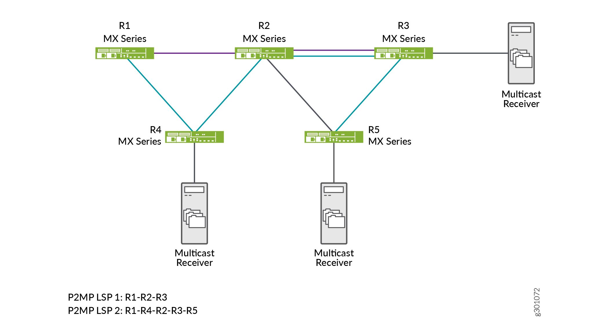
In this topology, R1 acts as an ingress (headend) router and
R2 as the transit (re-merge node) router. There are two sub LSP sessions
created in this network, LSP 1 and LSP 2. LSP 1 is a session established
among R1, R2, and R3 devices. LSP 2 is a session established between
R1, R4, R2, R3, and R5 devices. By default, the transit router allows
the re-merge to happen from both the sub LSPs and drops one of the
sub LSP branch traffic at the re-merge node. You can control this
re-merge behavior by enabling the no-re-merge CLI configuration
statement at the ingress router, or the no-p2mp-re-merge CLI configuration statement at the transit router.
If you enable the no-re-merge CLI configuration statement
at the ingress router (R1), only one of the two sub LSP sessions is
established. For example, if LSP 1 (R1-R2-R3) session is established
first, then the other sub LSP session (LSP 2) will not be established.
If you enable the no-p2mp-re-merge CLI configuration
statement at the transit router (R2), the transit router rejects the
re-merge of one of the sub LSPs and sends a path error message to
the ingress router (R1) preventing the ingress router from creating
the second P2MP LSP re-merge branch. You can use the show rsvp
statistics CLI command to view the path error message.
Modify the Default P2MP LSP Re-merge Behavior
You can modify the default re-merge behavior either at the ingress (headend) node, or at the transit node in a P2MP RSVP MPLS network.
On the ingress (headend router), disable the default re-merge behavior so that the ingress router does not do the path computation of sub LSPs which creates the re-merge condition. The default behavior allows the path computation of sub LSPs.
[edit protocols]
user@host#set mpls p2mp-lsp no-re-merge
On the transit router, disable the default re-merge behavior so that the transit router rejects the re-merge of sub LSPs.
[edit protocols]
user@host#set rsvp no-p2mp-re-merge
For inter-area, or inter-domain, or inter-AS RSVP P2MP LSPs,
use the single-abr CLI configuration statement at the ingress
(headend router) so that all the P2MP sub LSPs prefer to select the
same exit router (ABR or ASBR), thereby reducing the re-merge condition.
[edit protocols]
user@host#set mpls p2mp-lsp single-abr