Primary, Secondary, and Static LSP Configuration
Configuring Primary and Secondary LSPs
By default, an LSP routes itself hop-by-hop toward the egress router. The LSP tends to follow the shortest path as dictated by the local routing table, usually taking the same path as destination-based, best-effort traffic. These paths are “soft” in nature because they automatically re-route themselves whenever a change occurs in a routing table or in the status of a node or link.
To configure the path so that it follows a particular route, create a named path using
the path statement, as described in Creating
Named Paths. Then apply the named path by including the
primary or secondary statement. A named path can
be referenced by any number of LSPs.
To configure primary and secondary paths for an LSP, complete the steps in the following sections:
- Configuring Primary and Secondary Paths for an LSP
- Configuring the Revert Timer for LSPs
- Specifying the Conditions for Path Selection
- Configure a Primary Path
Configuring Primary and Secondary Paths for an LSP
The primary statement creates the primary path, which is the LSP’s
preferred path. The secondary statement creates an alternative
path. If the primary path can no longer reach the egress router, the alternative
path is used.
To configure primary and secondary paths, include the primary and
secondary statements:
            primary

            path-name {
    ...
}
secondary

            path-name {
    ...
}
You can include these statements at the following hierarchy levels:
-
[edit protocols mpls label-switched-path lsp-name] -
[edit logical-systems logical-system-name
                            protocols mpls label-switched-path lsp-name]
When the software switches from the primary to a secondary path, it continuously
attempts to revert to the primary path, switching back to it when it is again
reachable but no sooner than the time specified in the
revert-timer statement. (For more information, see Configuring the Connection Between Ingress and Egress Routers.)
You can configure zero or one primary path. If you do not configure a primary path, the first secondary path that is established is selected as the path.
You can configure zero or more secondary paths. All secondary paths are equal. The software does not attempt to switch among secondary paths. If the current secondary path is not available, the next one is tried in no particular order. To create a set of equal paths, specify secondary paths without specifying a primary path.
If you do not specify any named paths, or if the path that you specify is empty, the software makes all routing decisions necessary to reach the egress router.
Configuring the Revert Timer for LSPs
For LSPs configured with both primary and secondary paths, it is possible to configure the revert timer. If a primary path goes down and traffic is switched to the secondary path, the revert timer specifies the amount of time (in seconds) that the LSP must wait before it can revert traffic back to a primary path. If during this time, the primary path experiences any connectivity problems or stability problems, the timer is restarted. You can configure the revert timer for both static and dynamic LSPs.
The Junos OS also makes a determination as to which path is the preferred path. The preferred path is the path that has not encountered any difficulty in the last revert timer period. If both the primary and secondary paths have encountered difficulty, neither path is considered preferred. However, if one of the paths is dynamic and the other static, the dynamic path is selected as the preferred path.
If you have configured BFD on the LSP, Junos OS waits until the BFD session comes up on the primary path before starting the revert timer counter.
The range of values you can configure for the revert timer is 0 through 65,535 seconds. The default value is 60 seconds.
If you configure a value of 0 seconds, the traffic on the LSP, once switched from the primary path to the secondary path, remains on the secondary path permanently (until the network operator intervenes or until the secondary path goes down).
You can configure the revert timer for all LSPs on the router at the [edit
protocols mpls] hierarchy level or for a specific LSP at the
[edit protocols mpls label-switched-path
lsp-name] hierarchy level.
To configure the revert timer, include the revert-timer
statement:
revert-timer
seconds;
For a list of hierarchy levels at which you can include this statement, see the summary section for this statement.
Specifying the Conditions for Path Selection
When you have configured both primary and secondary paths for an LSP, you may need to ensure that only a specific path is used.
The select statement is optional. If you do not include it, MPLS
uses an automatic path selection algorithm.
The manual and unconditional options do the
following:
-
manual—The path is immediately selected for carrying traffic as long as it is up and stable. Traffic is sent to other working paths if the current path is down or degraded (receiving errors). This parameter overrides all other path attributes except theselect unconditionalstatement. -
unconditional—The path is selected for carrying traffic unconditionally, regardless of whether the path is currently down or degraded (receiving errors). This parameter overrides all other path attributes.Because the
unconditionaloption switches to a path without regard to its current status, be aware of the following potential consequences of specifying it:-
If a path is not currently up when you enable the
unconditionaloption, traffic can be disrupted. Ensure that the path is functional before specifying theunconditionaloption. -
Once a path is selected because it has the
unconditionaloption enabled, all other paths for the LSP are gradually cleared, including the primary and standby paths. No path can act as a standby to an unconditional path, so signaling those paths serves no purpose.
-
For a specific path, the manual and unconditional
options are mutually exclusive. You can include the select
statement with the manual option in the configuration of only one
of an LSP’s paths, and the select statement with the
unconditional option in the configuration of only one other of
its paths.
Enabling or disabling the manual and unconditional
options for the select statement while LSPs and their paths are up
does not disrupt traffic.
To specify that a path be selected for carrying traffic if it is up and stable for at
least the revert timer window, include the select statement with
the manual option:
select manual;
To specify that a path should always be selected for carrying traffic, even if it is
currently down or degraded, include the select statement with the
unconditional option:
select unconditional;
You can include the select statement at the following hierarchy
levels:
-
[edit protocols mpls label-switched-path lsp-name (primary | secondary) path-name] -
[edit logical-systems logical-system-name protocols mpls label-switched-path lsp-name (primary | secondary) path-name]
Configure a Primary Path
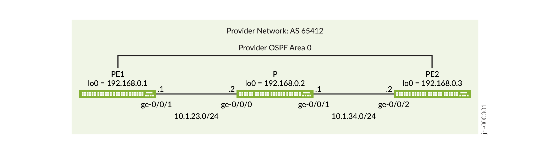
Follow these steps to configure a primary path with an ERO list, bandwidth, and priority. Refer to Figure 1 to see how the sample configuration relates to a network topology.
- In configuration mode, position yourself at the
protocols mplshierarchy level:[edit] user@R1# edit protocols mpls
- Configure the primary ERO
list:
[edit protocols mpls] user@R1# set path via-r2 10.1.23.2 strict user@R1# set path via-r2 10.1.34.2 strict
- Configure the
LSP:
[edit protocols mpls]
user@R1# set label-switched-path pe1-pe2 to 192.168.0.3;
- Configure the primary
path:
[edit protocols mpls]
user@R1# set label-switched-path pe1-pe2 primary via-p1
- Configure the
bandwidth:
[edit protocols mpls]
user@R1# set label-switched-path pe1-pe2 primary via-p1 bandwidth 35m
- Configure the priority
value:
[edit protocols mpls]
user@R1# set label-switched-path pe1-pe2 primary via-p1 priority 6 6
- Display the changes:
[edit protocols mpls]
user@R1# show
label-switched-path pe1-pe2 {
    to 192.168.0.3;
    primary via-p1 {
        bandwidth 35m;
        priority 6 6;
    }
}
path via-p1 {
    10.1.23.2 strict;
    10.1.34.2 strict;
}
Be sure to commit the changes when done. For a complete example of MPLS LSPs configured to support an MPLS-Based Layer 3 VPN see Example: Configure a Basic MPLS-Based Layer 3 VPN.
Configuring Hot Standby of Secondary Paths for LSPs
By default, secondary paths are set up only as needed. To have
the system maintain a secondary path in a hot-standby state indefinitely,
include the standby statement:
standby;
You can include this statement at the following hierarchy levels:
[edit protocols mpls label-switched-path lsp-name secondary][edit logical-systems logical-system-name protocols mpls label-switched-path lsp-name secondary]
The hot-standby state is meaningful only on secondary paths.
Maintaining a path in a hot-standby state enables swift cutover to
the secondary path when downstream routers on the current active path
indicate connectivity problems. Although it is possible to configure
the standby statement at the [edit protocols mpls
label-switched-path lsp-name primary path-name] hierarchy level, it has no effect on
router behavior.
If you configure the standby statement at the following
hierarchy levels, the hot-standby state is activated on all secondary
paths configured beneath that hierarchy level:
[edit protocols mpls][edit protocols mpls label-switched-path lsp-name][edit logical-systems logical-system-name protocols mpls][edit logical-systems logical-system-name protocols mpls label-switched-path lsp-name]
The hot-standby state has two advantages:
It eliminates the call-setup delay during network topology changes. Call setup can suffer from significant delays when network failures trigger large numbers of LSP reroutes at the same time.
A cutover to the secondary path can be made before RSVP learns that an LSP is down. There can be significant delays between the time the first failure is detected by protocol machinery (which can be an interface down, a neighbor becoming unreachable, a route becoming unreachable, or a transient routing loop being detected) and the time an LSP actually fails (which requires a timeout of soft state information between adjacent RSVP routers). When topology failures occur, hot-standby secondary paths can usually achieve the smallest cutover delays with minimal disruptions to user traffic.
When the primary path is considered to be stable again, traffic is automatically switched from the standby secondary path back to the primary path. The switch is performed no faster than twice the retry-timer interval and only if the primary path exhibits stability throughout the entire switch interval.
The drawback of the hot-standby state is that more state information must be maintained by all the routers along the path, which requires overhead from each of the routers.
When viewed with inet.3, the same LSP may appear
to be shown twice as the active route (both primary and secondary),
even though traffic actually is being forwarded over the primary path
LSP only. This is normal output, and reflects only that the secondary
standby path is available.
Configuring Static LSPs
To configure static LSPs, configure the ingress router and each router along the path up to and including the penultimate router.
To configure static MPLS, perform the following tasks:
- Configuring the Ingress Router for Static LSPs
- Configuring the Transit and Penultimate Routers for Static LSPs
- Configuring a Bypass LSP for the Static LSP
- Configuring the Protection Revert Timer for Static LSPs
- Configuring Static Unicast Routes for Point-to-Multipoint LSPs
Configuring the Ingress Router for Static LSPs
The ingress router checks the IP address in the incoming packet’s destination address field and, if it finds a match in the routing table, applies the label associated with that address to the packets. The label has forwarding information associated with it, including the address of the next-hop router, and the route preference and CoS values.
To configure static LSPs on the ingress router, include the ingress
statement:
ingress {
    bandwidth bps;
    class-of-service cos-value;
    description string;
    install {
        destination-prefix <active>;
    }
    link-protection bypass-name name;
    metric metric;
    next-hop (address | interface-name | address/interface-name);
    no-install-to-address;
    node-protection bypass-name name next-next-label label;
    policing {
        filter filter-name;
        no-auto-policing;
    }
    preference preference;
    push out-label;
    to address;
}
You can include these statements at the following hierarchy levels:
-
[edit protocols mpls static-label-switched-path static-lsp-name] -
[edit logical-systems logical-system-name
                            protocols mpls static-label-switched-path
                                static-lsp-name]
When you configure a static LSP on the ingress router, the next-hop,
push, and to statements are required; the
other statements are optional.
The configuration for a static LSP on the ingress router includes the following:
-
Criteria for analyzing an incoming packet:
-
The
installstatement creates an LSP that handles IPv4 packets. All static MPLS routes created using theinstallstatement are installed in inet.3 routing table, and the creating protocol is identified as mpls. This process is no different from creating static IPv4 routes at the[edit routing-options static]hierarchy level. -
In the
tostatement, you configure the IP destination address to check when incoming packets are analyzed. If the address matches, the specified outgoing label (push out-label) is assigned to the packet, and the packet enters an LSP. Manually assigned outgoing labels can have values from 0 through 1,048,575. This IP address is installed into inet.3 table (by default) by the mpls protocol.
-
-
The
next-hopstatement, which supplies the IP address of the next hop to the destination. You can specify this as the IP address of the next hop, the interface name (for point-to-point interfaces only), or asaddress/interface-nameto specify an IP address on an operational interface. When the next hop is on a directly attached interface, the route is installed in the routing table. You cannot configure a LAN or nonbroadcast multiaccess (NBMA) interface as a next-hop interface. -
Properties to apply to the LSP (all are optional):
-
Bandwidth reserved for this LSP (
bandwidth
                                    bps
) -
Link protection and node protection to apply to the LSP (
bypass
                                    bypass-name, link-protection bypass-name name,
                                        node-protection bypass-name next-next-label
                                        label
) -
Metric value to apply to the LSP (
metric) -
Class-of-service value to apply to the LSP (
class-of-service) -
Preference value to apply to the LSP (
preference) -
Traffic policing to apply to the LSP (
policing) -
Text description to apply to the LSP (
description) -
Install or no-install policy (
installorno-install-to-address)
-
To determine whether a static ingress route is installed, use the command
show route table inet.0 protocol static. You can also see the
route in table inet.3. The sample output uses the command show route
10.1.45.2 to show both tables inet.0 and inet.3. The
Push keyword denotes that a label is to be added in front of an
IP packet.
user@R2> show route 10.1.45.2
inet.0: 17 destinations, 17 routes (17 active, 0 holddown, 0 hidden)
+ = Active Route, - = Last Active, * = Both
10.1.45.2/32 *[Static/5] 00:48:38
> to 10.1.23.2 via ge-0/0/0.0, Push 1000123
inet.3: 1 destinations, 1 routes (1 active, 0 holddown, 0 hidden)
+ = Active Route, - = Last Active, * = Both
10.1.45.2/32 *[MPLS/6/1] 00:48:38, metric 0
> to 10.1.23.2 via ge-0/0/0.0, Push 1000123Example: Configuring the Ingress Router
Configure the ingress router for a static LSP that consists of four routers (see Figure 2).
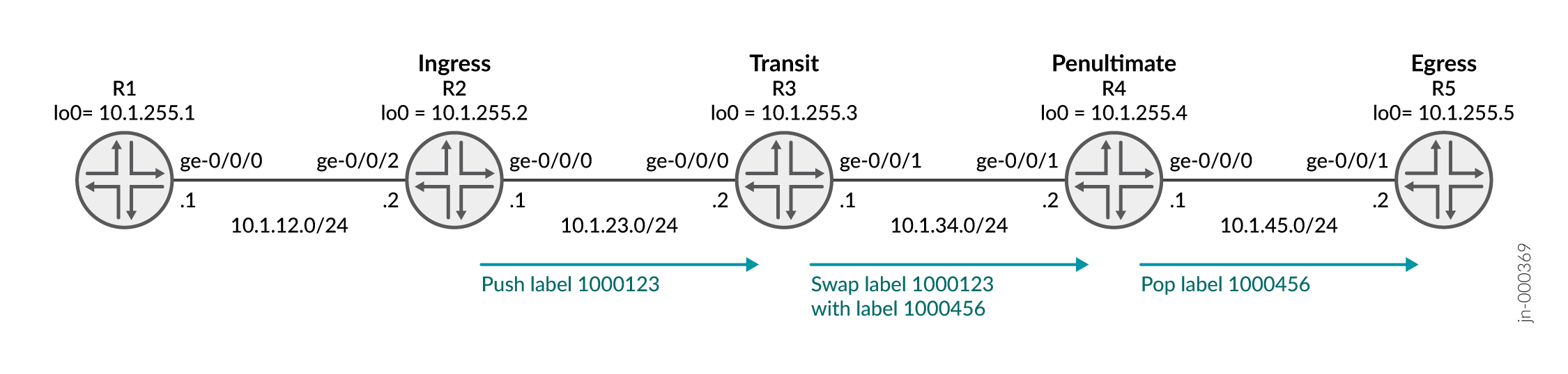
This example does not cover the R1 and R5 configurations. R1 and R5 have interface configuration and a static route to reach the other routers.
For packets addressed to 10.1.45.2, assign label
1000123 and transmit them to the next-hop router at
10.1.23.2:
[edit]
user@R2# show
interfaces {
ge-0/0/0 {
unit 0 {
family inet {
address 10.1.23.1/24;
}
family mpls;
}
}
ge-0/0/2 {
unit 0 {
family inet {
address 10.1.12.2/24;
}
}
}
lo0 {
unit 0 {
family inet {
address 10.1.255.2/32;
}
}
}
}
routing-options {
router-id 10.1.255.2;
static {
route 10.1.45.2/32 {
static-lsp-next-hop path1;
}
}
}
protocols {
mpls {
interface ge-0/0/0.0;
static-label-switched-path path1 {
ingress {
next-hop 10.1.23.2;
to 10.1.45.2;
push 1000123;
}
}
}
ospf {
traffic-engineering;
area 0.0.0.0 {
interface ge-0/0/0.0;
interface ge-0/0/2.0 {
passive;
}
interface lo0.0;
}
}
}To determine whether the static ingress route is installed, use the command
show route 10.1.45.2.
The sample output shows the Push 1000123 keyword identifies the
route.
user@R2> show route 10.1.45.2

inet.0: 17 destinations, 17 routes (17 active, 0 holddown, 0 hidden)
+ = Active Route, - = Last Active, * = Both

10.1.45.2/32       *[Static/5] 01:08:05
                    >  to 10.1.23.2 via ge-0/0/0.0, Push 1000123

inet.3: 1 destinations, 1 routes (1 active, 0 holddown, 0 hidden)
+ = Active Route, - = Last Active, * = Both

10.1.45.2/32       *[MPLS/6/1] 01:08:05, metric 0
                    >  to 10.1.23.2 via ge-0/0/0.0, Push 1000123
Configuring the Transit and Penultimate Routers for Static LSPs
The transit and penultimate routers perform similar functions—they modify the label that has been applied to a packet. An transit router can change the label. An penultimate router removes the label and continues forwarding the packet to its destination.
To configure static LSPs on transit and penultimate routers, include the
transit statement:
static-label-switched-path lsp-name {
    transit incoming-label {
        bandwidth bps;
        description string;
        link-protection bypass-name name;
        next-hop (address | interface-name | address/interface-name);
        node-protection bypass-name name next-next-label label;
        pop;
        swap out-label;
    }
You can include these statements at the following hierarchy levels:
-
[edit protocols mpls static-label-switched-path static-lsp-name] -
[edit logical-systems logical-system-name
                            protocols mpls static-label-switched-path
                                static-lsp-name]
For the transit statement configuration, the
next-hop and pop | swap statements are
required. The remaining statements are optional.
Each statement within the transit statement consists of the
following parts:
-
Packet label (specified in the
transitstatement) -
The
next-hopstatement, which supplies the IP address of the next hop to the destination. The address is specified as the IP address of the next hop, or the interface name (for point-to-point interfaces only), oraddressandinterface-nameto specify an IP address on an operational interface. When the specified next hop is on a directly attached interface, this route is installed in the routing table. You cannot configure a LAN or NBMA interface as a next-hop interface. -
Operation to perform on the labeled packet:
-
For penultimate routers, you generally just remove the packet’s label altogether (
pop) and continue forwarding the packet to the next hop. However, if the previous router removed the label, the egress router examines the packet’s IP header and forwards the packet toward its IP destination. -
For transit routers only, exchange the label for another label (
swap out-label). Manually assigned incoming labels can have values from 1,000,000 through 1,048,575. Manually assigned outgoing labels can have values from 0 through 1,048,575.
-
-
Label properties to apply to the packet (all are optional):
-
Bandwidth reserved for this route (
bandwidth
                                    bps
). -
Link-protection and node-protection to apply to the LSP (
bypass
                                    bypass-name, link-protection bypass-name name,
                                        node-protection bypass-name next-next-label
                                        label
). -
Text description to apply to the LSP (specified in the
descriptionstatement).
-
The routes are installed in the default MPLS routing table, mpls.0, and the creating
protocol is identified as MPLS. To verify that a route is properly installed, use
the command show route table mpls.0. Sample output follows:
root@R3> show route table mpls.0
...
1000123            *[MPLS/6] 00:51:34, metric 1
                    >  to 10.1.34.2 via ge-0/0/1.0, Swap 1000456
You can configure a revert timer for a static LSP transiting a transit router. After
traffic has been switched to a bypass static LSP, it is typically switched back to
the primary static LSP when it comes back up. There is a configurable delay in the
time (called the revert timer) between when the primary static LSP comes up and when
traffic is reverted back to it from the bypass static LSP. This delay is needed
because when the primary LSP comes back up, it is not certain whether all of the
interfaces on the downstream node of the primary path have come up yet. You can
display the revert timer value for an interface using the show mpls
interface detail
command.
Example: Configuring a Transit Router
For packets labeled 1000123 arriving on interface
ge-0/0/0, assign the label 1000456, and
transmit them to the next-hop router at 10.1.34.2:
[edit]
user@R3# show
interfaces {
    ge-0/0/0 {
        unit 0 {
            family inet {
                address 10.1.23.2/24;
            }
            family mpls;
        }
    }
    ge-0/0/1 {
        unit 0 {
            family inet {
                address 10.1.34.1/24;
            }
            family mpls;
        }
    }
    lo0 {
        unit 0 {
            family inet {
                address 10.1.255.3/32;
            }
        }
    }
}
routing-options {
    router-id 10.1.255.3;
}
protocols {
    mpls {
        interface ge-0/0/0.0;
        interface ge-0/0/1.0;
        static-label-switched-path path1 {
            transit 1000123 {
                next-hop 10.1.34.2;
                swap 1000456;
            }
        }
    }
    ospf {
        traffic-engineering;
        area 0.0.0.0 {
            interface ge-0/0/0.0;
            interface ge-0/0/1.0;
            interface lo0.0;
        }
    }
}
To determine whether the route is installed, use the command show route
table mpls.0.
Sample output follows. The Swap 1000456 keyword identifies the
route.
root@R3> show route table mpls.0
...
1000123            *[MPLS/6] 00:57:17, metric 1
                    >  to 10.1.34.2 via ge-0/0/1.0, Swap 1000456
Example: Configuring a Penultimate Router
For packets labeled 1000456 arriving on interface
ge-0/0/1, remove the label and transmit the packets to the
next-hop router at 10.1.45.2:
[edit]
user@R4# show
interfaces {
    ge-0/0/0 {
        unit 0 {
            family inet {
                address 10.1.45.1/24;
            }
            family mpls;
        }
    }
    ge-0/0/1 {
        unit 0 {
            family inet {
                address 10.1.34.2/24;
            }
            family mpls;
        }
    }
    lo0 {
        unit 0 {
            family inet {
                address 10.1.255.4/32;
            }
        }
    }
}
routing-options {
    router-id 10.1.255.4;
}
protocols {
    mpls {
        interface ge-0/0/1.0;
        interface ge-0/0/0.0;
        static-label-switched-path path1 {
            transit 1000456 {
                next-hop 10.1.45.2;
                pop;
            }
        }
    }
    ospf {
        traffic-engineering;
        area 0.0.0.0 {
            interface ge-0/0/1.0;
            interface lo0.0;
            interface ge-0/0/0.0;
        }
    }
}
To determine whether the route is installed, use the command show route
table mpls.0.
Sample output follows. The Pop keyword identifies the route.
user@R4> show route table mpls.0
...
1000456            *[MPLS/6] 00:50:55, metric 1
                    >  to 10.1.45.2 via ge-0/0/0.0, Pop
1000456(S=0)       *[MPLS/6] 00:50:55, metric 1
                    >  to 10.1.45.2 via ge-0/0/0.0, Pop
To verify end-to-end reachability and that the traffic is using the LSP, use the
command traceroute 10.1.45.2 on R1.
user@R1> traceroute 10.1.45.2
traceroute to 10.1.45.2 (10.1.45.2), 30 hops max, 52 byte packets
 1  10.1.12.2 (10.1.12.2)  2.601 ms  2.261 ms  2.172 ms
 2  10.1.23.2 (10.1.23.2)  3.953 ms  3.425 ms  3.928 ms
     MPLS Label=1000123 CoS=0 TTL=1 S=1
 3  10.1.34.2 (10.1.34.2)  4.616 ms  4.300 ms  4.535 ms
     MPLS Label=1000456 CoS=0 TTL=1 S=1
 4  10.1.45.2 (10.1.45.2)  5.965 ms  5.232 ms  5.289 ms
Configuring a Bypass LSP for the Static LSP
To enable a bypass LSP for the static LSP, configure the bypass
statement:
bypass bypass-name {
    bandwidth bps;
    description string;
    next-hop (address | interface-name | address/interface-name);
    next-table
    push out-label;
    to address;
}
Configuring the Protection Revert Timer for Static LSPs
For static LSPs configured with a bypass static LSP, it is possible to configure the protection revert timer. If a static LSP goes down and traffic is switched to the bypass LSP, the protection revert timer specifies the amount of time (in seconds) that the LSP must wait before it can revert back to the original static LSP.
The range of values you can configure for the protection revert timer is 0 through 65,535 seconds. The default value is 5 seconds.
If you configure a value of 0 seconds, the traffic on the LSP, once switched from the original static LSP to the bypass static LSP, remains on the bypass LSP permanently (until the network operator intervenes or until the bypass LSP goes down).
You can configure the protection revert timer for all dynamic LSPs on the router at
the [edit protocols mpls] hierarchy level or for a specific LSP at
the [edit protocols mpls label-switched-path
lsp-name] hierarchy level.
To configure the protection revert timer for static LSPs include the
protection-revert-time statement:
protection-revert-time seconds;
For a list of hierarchy levels at which you can include this statement, see the summary section for this statement.
Configuring Static Unicast Routes for Point-to-Multipoint LSPs
You can configure a static unicast IP route with a point-to-multipoint LSP as the next hop. For more information about point-to-multipoint LSPs, see Point-to-Multipoint LSPs Overview, Configuring Primary and Branch LSPs for Point-to-Multipoint LSPs, and Configuring CCC Switching for Point-to-Multipoint LSPs.
To configure a static unicast route for a point-to-multipoint LSP, complete the following steps:
-
On the ingress PE router, configure a static IP unicast route with the point-to-multipoint LSP name as the next hop by including the
p2mp-lsp-next-hopstatement:p2mp-lsp-next-hop point-to-multipoint-lsp-next-hop;
You can include this statement at the following hierarchy levels:
-
[edit routing-options static route route-name] -
[edit logical-systems logical-system-name
                                    routing-options static route
                                    route-name]
-
-
On the egress PE router, configure a static IP unicast route with the same destination address configured in Step 1 (the address configured at the
[edit routing-options static
                            route]
hierarchy level) by including thenext-hopstatement:next-hop address;
You can include this statement at the following hierarchy levels:
-
[edit routing-options static route route-name] -
[edit logical-systems logical-system-name
                                    routing-options static route
                                    route-name]
Note:CCC and static routes cannot use the same point-to-multipoint LSP.
-
For more information on static routes, see the Junos OS Routing Protocols Library for Routing Devices.
The following show route command output displays a unicast static
route pointing to a point-to-multipoint LSP on the ingress PE router where the LSP
has two branch next hops:
user@host> show route 5.5.5.5 detail
inet.0: 29 destinations, 30 routes (28 active, 0 holddown, 1 hidden)
5.5.5.5/32 (1 entry, 1 announced)
        *Static Preference: 5
                Next hop type: Flood
                Next hop: via so-0/3/2.0 weight 1
                Label operation: Push 100000
                Next hop: via t1-0/1/1.0 weight 1
                Label operation: Push 100064
                State: <Active Int Ext>
                Local AS: 10458
                Age: 2:41:15
                Task: RT
                Announcement bits (2): 0-KRT 3-BGP.0.0.0.0+179
                AS path: I
Configuring Static Label Switched Paths for MPLS (CLI Procedure)
Configuring static label-switched paths (LSPs) for MPLS is similar to configuring static routes on individual switches. As with static routes, there is no error reporting, liveliness detection, or statistics reporting.
To configure static LSPs, configure the ingress switch and each provider switch along the path up to and including the egress switch.
For the ingress switch, configure which packets to tag (based on the packet’s destination IP address), configure the next switch in the LSP, and the tag to apply to the packet. Manually assigned labels can have values from 0 through 1,048,575. Optionally, you can apply preference, class-of-service (CoS) values, node protection, and link protection to the packets.
For the transit switches in the path, configure the next switch in the path and the tag to apply to the packet. Manually assigned labels can have values from 1,000,000 through 1,048,575. Optionally, you can apply node protection and link protection to the packets.
For the egress switch, you generally just remove the label and continue forwarding the packet to the IP destination. However, if the previous switch removed the label, the egress switch examines the packet’s IP header and forwards the packet toward its IP destination.
Before you configure an LSP, you must configure the basic components for an MPLS network:
Configure two PE switches. See Configuring MPLS on Provider Edge EX8200 and EX4500 Switches Using Circuit Cross-Connect.
Configure one or more provider switches. See Configuring MPLS on EX8200 and EX4500 Provider Switches.
This topic describes how to configure an ingress PE switch, one or more provider switches, and an egress PE switch for static LSP:
Configuring the Ingress PE Switch
To configure the ingress PE switch:
Configuring the Provider and the Egress PE Switch
To configure a static LSP for MPLS on the provider and egress provider edge switch:
Configuring Static Label Switched Paths for MPLS
Configuring static label-switched paths (LSPs) for MPLS is similar to configuring static routes on individual switches. As with static routes, there is no error reporting, liveliness detection, or statistics reporting.
To configure static LSPs, configure the ingress PE switch and each provider switch along the path up to and including the egress PE switch.
For the ingress PE switch, configure which packets to tag (based on the packet’s destination IP address), configure the next switch in the LSP, and the tag to apply to the packet. Manually assigned labels can have values from 0 through 1,048,575.
For the transit switches in the path, configure the next switch in the path and the tag to apply to the packet. Manually assigned labels can have values from 1,000,000 through 1,048,575.
The egress PE switch removes the label and forwards the packet to the IP destination. However, if the previous switch removed the label, the egress switch examines the packet’s IP header and forwards the packet toward its IP destination.
Before you configure a static LSP, you must configure the basic components for an MPLS network:
Configure two PE switches. See Configuring MPLS on Provider Edge Switches.
Note:Do not configure LSPs at the
[edit protocols mpls
label-switched-path]
hierarchy level on the PE switches.Configure one or more provider switches. See Configuring MPLS on Provider Switches.
This topic describes how to configure an ingress PE switch, one or more provider switches, and an egress PE switch for static LSP:
Configuring the Ingress PE Switch
To configure the ingress PE switch:
Configuring the Provider and the Egress PE Switch
To configure a static LSP for MPLS on the provider and egress PE switch: