Port Speed Overview
Learn about the port speed on a switch or line card, channelization support, and the port speed configuration.
Port speed is the maximum data that the line card transmits through a port in a second. You can measure port speed in kilobits per second (Kbps), gigabits per second (Gbps), or terabits per second (Tbps).
Port types:
- Switch ports: Devices plug into a switch port. You can also use the switch ports as uplink ports.
- Uplink ports: These ports are faster than switch ports. You can use uplink ports to connect two switches.
- Console ports: Use the console ports to:
- Control a switch. The console port is usually on the rear side of a switch.
- Program, configure, and turn on or turn off the switch.
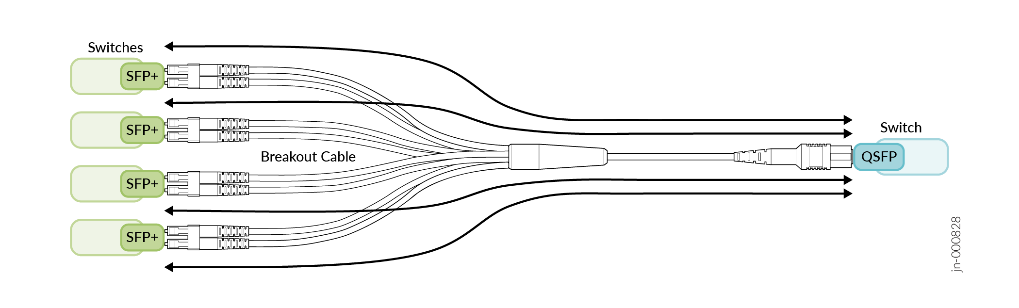
Port Speed Channelization
You can split a high-speed port on a network equipment into several low-speed ports. For example, you can channelize a 100 Gbps port into four 25 Gbps ports.
Port Speed Autonegotiation
The autonegotiation mechanism helps ports determine the optimal values of speed and duplex mode.
Autonegotiation is a signaling mechanism used by Ethernet over twisted pair. In autonegotiation, the connected devices first share their capabilities regarding speed and duplex mode and then choose the highest performance transmission mode they both support. Autonegotiation takes place when a device and a switch have different NIC cards.
Interface Naming Conventions
Each interface name includes a unique identifier and follows a naming convention. When you configure the interface, use the interface name. You can either configure a port as a single interface (non-channelized interface) or partition the port into smaller data channels or multiple interfaces (channelized interfaces).
When multiple interfaces are supported on a physical port, you use the colon (:) notation in the interface naming conventions as a delimiter to differentiate the multiple interfaces on a physical port. In the interface naming convention, xe-x/y/z:channel:
- x refers to the FPC slot number.
- y refers to the PIC slot number.
- z refers to the physical port number.
-
channelrefers to the number of channelized interfaces.
When the 40-Gigabit Ethernet interfaces (et-fpc/pic/port) are channelized as 10-Gigabit Ethernet interfaces, the interface appears in the xe-fpc/pic/port: channel format, and channel is a value of 0 through 3.
Interfaces |
Non-Channelized Interfaces Naming Formats |
Channelized Interfaces Naming Formats |
|---|---|---|
10-Gigabit Ethernet Interfaces |
Prefix is |
Prefix is |
| 25-Gigabit Ethernet Interfaces, 40-Gigabit Ethernet Interfaces, 100-Gigabit Ethernet Interfaces, 200-Gigabit Ethernet Interfaces, and 400-Gigabit Ethernet Interfaces. | Prefix is |
Prefix is et-. The interface name appears in the et-fpc/pic/port:channel format. |