Multinode High Availability in Azure Cloud
Read this document to understand how to configure Multinode High Availability on vSRX instances deployed on Azure cloud.
Overview
You can configure Multinode High Availability on vSRX Virtual Firewalls deployed in the Microsoft Azure Cloud. Microsoft Azure is Microsoft's application platform for the public cloud. It is an open, flexible, enterprise-grade cloud computing platform for building, deploying, and managing applications and services through a global network of Microsoft-managed data centers.
You can configure a pair of vSRX virtual firewalls on Azure to operate as in an active/backup Multinode high availability configuration. Participating nodes run both active control and data planes at the same time. The nodes backup each other to ensure a fast synchronized failover in case of a system or hardware failure. The interchassis link (ICL) connection between the two devices synchronizes and maintains the state information and handles device failover scenarios.
You can configure Multinode High Availability on vSRX Virtual Firewall VMs by customizing firewall deployment settings in Microsoft Azure Cloud.
IPsec VPN Support
Starting in Junos OS Release 24.4R1, we support IPsec VPN for active/backup Multinode High Availability in Azure Cloud deployments.
Limitation
Multinode High Availability doesn’t support multiple SRG configurations (active/active) in public cloud deployments. Active/backup mode supports SRG0 or SRG1. IPsec VPN tunnel anchors at the SRG1, which works in a stateful active/backup mode. All VPN tunnels terminate on the device where the SRG1 is active.
Architecture
Figure 1 shows two vSRX Virtual Firewall instances form a Multinode high availability pair in the in the Azure cloud. One vSRX Virtual Firewall instance acts as the active node and the other instance acts as the backup node. Both nodes connect to each other using an ICL to synchronize and maintain state information and to handle device failover scenarios.
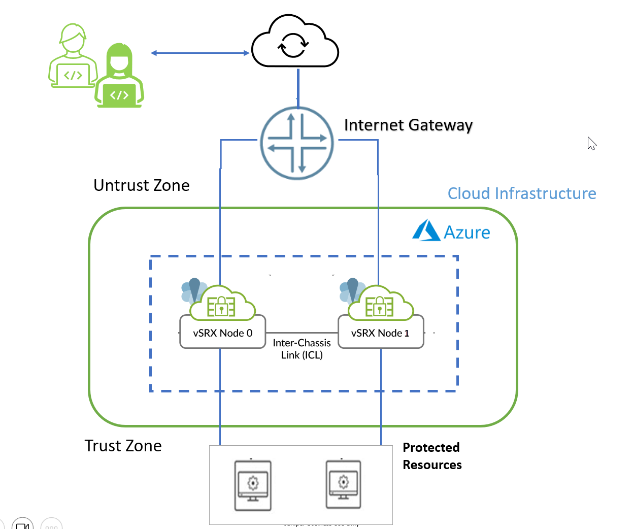
vSRX Virtual Firewall requires two public IP addresses and one or more private IP address for each individual instance group. The public subnets consist of one for the management interface (fxp0) and one for a revenue (data) interface. You can use any four revenue interfaces for the subnet configuration. The private interface is connected to the protected resources. It ensures that all traffic between applications on the private subnet and the Internet must pass through the vSRX Virtual Firewall instance.
For Multinode High Availability on Azure, you must deploy both the firewalls within the same Azure Resource Group. An Azure Resource Group is a logical container that holds related resources for an Azure solution. It can include all the resources for the solution, or only those resources that you want to manage as a group.
You must allocate a node-specific primary address to each node and a common secondary or floating IP address to both the nodes. The secondary IP address, which acts as a floating IP address, is always attached to the active node. In case of failure on the current active node, the secondary IP address transitions from the failed active node to the current active node. The new active node ensures the continue flow of traffic.
Initially both the nodes are launched with predefined tags stating which one is the owner of the secondary IP address during boot up. That particular node starts operating as the active node and other one starts as a backup node.
Split-Brain Protection
The split-brain scenario refers to a situation where both nodes of the Multinode High Availability system become stuck in the same state, either active or backup, when the inter-chassis link (ICL) between the nodes is down. To prevent this state, both nodes attempt to probe the primary IP address of the trust or the untrust interface, based on the configuration.
When an Interchassis Link (ICL) experiences a failure along with a probe failure, the node that does not receive a reply from its peer will take on the active role. However, if the probe succeeds and confirms that the peer node is still operational, the node will maintain its current state. This probing process persists until the ICL is restored.
Example: Configure Multinode High Availability in Azure Cloud Deployment
Read this topic to understand how to configure the Multinode High Availability solution on SRX Series Firewalls.
You can configure a pair of vSRX virtual firewalls on Azure to operate as in an active/backup Multinode high availability configuration. Participating nodes run both active control and data planes at the same time. The nodes backup each other to ensure a fast synchronized failover in case of a system or hardware failure. The interchassis link (ICL) connection between the two devices synchronizes and maintains the state information and handles device failover scenarios.
In this example, we'll show you how to configure Multinode High Availability on two vSRX Virtual Firewall instances deployed in the Azure Cloud.
Reading Time |
45 Minutes |
Configuration Time |
1.5 hour |
Example Prerequisites
VMs requirements |
Two vSRX Virtual Firewalls deployed on Azure Cloud |
Software requirements |
Junos OS Release 23.4R1 or later releases |
Licensing requirements |
Use vSRX Virtual Firewall license or request an evaluation license. Licenses can be procured from the Juniper Networks License Management System (LMS). Check the following links for details:
|
Before You Begin
Benefits |
Increases the availability of vSRX Series firewalls deployed in Azure that results in improved reliability and reduced downtime. |
Know more |
|
Learn more |
Functional Overview
Technologies used |
|
Primary verification tasks |
|
Topology Overview
Figure 2 shows the topology used in this example.
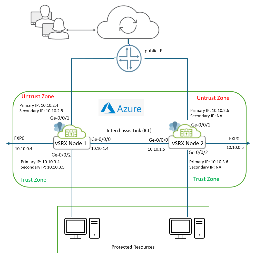
The topology illustrates a Multinode High Availability (MNHA) setup using two vSRX Virtual Firewall instances—Node 1 and Node 2—deployed in Microsoft Azure. This configuration ensures redundancy and seamless failover for secure traffic handling.
Table 2 and Table 3 provide interface and IP address details used in this example.
| Interface | Subnet | Private IP | Public IP | Role/Notes |
| fxp0 | 10.10.0.0/24 | 10.10.0.4 |
203.0.113.33 | Management Interface |
| ge-0/0/0 | 10.10.1.0/24 | 10.10.1.4 |
- | Connects ICL (Inter-Cluster Link) |
| ge-0/0/1 (Primary) | 10.10.2.0/24 | 10.10.2.4 |
- | Connects untrust zone to Internet |
| ge-0/0/1 (Secondary) | 10.10.2.0/24 | 10.10.2.5 |
198.51.100.253 |
Acts as secondary IP |
| ge-0/0/2 (Primary) | 10.10.3.0/24 | 10.10.3.4 |
- | Connects trust zone to protected subnet |
| ge-0/0/2 (Secondary) | 10.10.3.0/24 | 10.10.3.5 |
- | Secondary IP |
| Interface | Subnet | Private IP | Public IP | Role/Notes |
| fxp0 | 10.10.0.0/24 | 10.10.0.5 |
203.0.113.35 | Management interface |
| ge-0/0/0 | 10.10.1.0/24 | 10.10.1.5 |
- | Connects to ICL |
| ge-0/0/1 (Primary) | 10.10.2.0/24 | 10.10.2.6 |
- | Connects untrust zone to Internet |
| ge-0/0/2 (Primary) | 10.10.3.0/24 | 10.10.3.6 |
- | Connects trust zone to protected subnet |
Key Components
vSRX Nodes
- Node 1 and Node 2 act as firewall peers in an MNHA cluster.
- Each node has:
- Untrust Interface (Ge-0/0/1): Connects to the public subnet, which has Internet access
- Trust Interface (Ge-0/0/2): Connects to protected resources in the private subnet.
- Management Interface (FXP0): Used for out-of-band management.
Public and Private Subnets
- Both vSRX nodes are placed in the public subnet to provide connectivity to the Internet gateway.
- The untrust side handles external traffic.
- Protected resources are located in the private subnet, connected to the trust interfaces of both nodes.
Interchassis Link (ICL)
- Interfaces Ge-0/0/0 on both nodes form the ICL.
- Uses routable IP addresses (10.10.1.4 and 10.10.1.5).
To deploy vSRX Virtual Firewall instances in Microsoft Azure, you must select the vSRX image from the Azure Marketplace and customize the virtual machine settings and associated dependencies according to your network requirements. This manual deployment approach is often required when configuring an MNHA setup for vSRX VMs. While this use case could also be automated using a CloudFormation template, such a template is currently not available.
Let’s dive into the details of each step for deploying the vSRX Virtual Firewall on Microsoft Azure.
Azure Portal Setup
- Create Resource Group
- Administrative Access Setup
- Create a Virtual Network (VNet) & Subnets
- Create Public IP Addresses
- Create a Network Security Group (NSG)
- Create a Storage Account
- Deploy vSRX VMs
- Create and Assign I AM Permissions for a Managed Identity
- Create Interface Tags
- Create Network Interfaces
- Assign IP Addresses for Interfaces
Once you complete all configurations, Use Azure Portal serial console or remote SSH to log in to the vSRX Virtual Firewall VMs.
Now that all configurations required on Azure portal are complete, let’s start configuration on vSRX Virtual Firewall using CLI.
Ensure you use the latest version of vSRX software image (23.4R1 or later). You can directly upgrade the Junos OS for vSRX Virtual Firewall software using the CLI. Upgrading or downgrading Junos OS can take several hours, depending on the size and configuration of the network. You download the desired Junos OS Release for vSRX Virtual Firewall.tgz file from the Juniper Networks website. See Migration, Upgrade, and Downgrade Instructions.
Configure vSRX Virtual Firewalls
The Junos IKE package is recommended on your SRX Series Firewalls for Multinode High Availability configuration. This package is available as a default package or as an optional package on SRX Series Firewalls. See Support for Junos IKE Package for details.
If the package is not installed by default on your SRX Series firewall, use the following command to install it. You require this step for ICL encryption.
user@host> request system software add optional://junos-ike.tgz
Verified junos-ike signed by PackageProductionECP256_2022 method ECDSA256+SHA256
Rebuilding schema and Activating configuration...
mgd: commit complete
Restarting MGD ...

......
Restart cli using the new version ? [yes,no] (yes)
Verification
Use the show commands to confirm that the configuration is working properly.
| Command | Verification Task |
|---|---|
|
Display details of the MNHA status on your security device including health status of the peer node. |
show security cloud high- availability information |
Display status about MNHA deployment on public cloud (AWS or Azure). |
Check Multinode High Availability Details
Purpose
View and verify the details of the Multinode High Availability setup configured on your vSRX Virtual Firewall instance.
Action
From operational mode, run the following command on both the devices.
On Node 1 (Active Node)
user@srx-01> show chassis high-availability information
Node failure codes:
    HW  Hardware monitoring    LB  Loopback monitoring
    MB  Mbuf monitoring        SP  SPU monitoring
    CS  Cold Sync monitoring   SU  Software Upgrade

Node Status: ONLINE
Local-id: 1
Local-IP: 10.10.1.4
HA Peer Information:

    Peer Id: 2        IP address: 10.10.1.5     Interface: ge-0/0/0.0
    Routing Instance: default
    Encrypted: YES    Conn State: UP
    Configured BFD Detection Time: 5 * 400ms
    Cold Sync Status: COMPLETE

SRG failure event codes:
    BF  BFD monitoring
    IP  IP monitoring
    IF  Interface monitoring
    CP  Control Plane monitoring

Services Redundancy Group: 1
        Deployment Type: CLOUD
        Status: ACTIVE
        Activeness Priority: 200
        Preemption: DISABLED
        Process Packet In Backup State: NO
        Control Plane State: READY
        System Integrity Check: N/A
        Failure Events: NONE
        Peer Information:
          Peer Id: 2
          Status : BACKUP
          Health Status: HEALTHY
Failover Readiness: READYuser@srx-01> show chassis high-availability information detail
Node level Information:
Node Status: ONLINE
Local-id: 1
Local-IP: 10.10.1.4
HA Peer Information:
Peer-ID: 2 IP address: 10.10.1.5 Interface: ge-0/0/0.0
Routing Instance: default
Encrypted: YES Conn State: UP
Cold Sync Status: COMPLETE
Internal Interface: st0.16000
Internal Local-IP: 180.100.1.1
Internal Peer-IP: 180.100.1.2
Internal Routing-instance: __juniper_private1__
Packet Statistics:
Receive Error : 0 Send Error : 0
Packet-type Sent Received
SRG Status Msg 2 4
SRG Status Ack 4 1
Attribute Msg 2 1
Attribute Ack 1 1
HA Peer Conn events:
Jan 19 05:01:35.819 : HA Peer 180.100.1.2 BFD conn came up
Cold Synchronization:
Status:
Cold synchronization completed for: N/A
Cold synchronization failed for: N/A
Cold synchronization not known for: N/A
Current Monitoring Weight: 0
Progress:
CS Prereq 1 of 1 SPUs completed
1. if_state sync 1 SPUs completed
2. ha peer conn 1 SPUs completed
3. policy data sync 1 SPUs completed
4. cp ready 1 SPUs completed
5. VPN data sync 1 SPUs completed
6. IPID data sync 1 SPUs completed
7. All SPU ready 1 SPUs completed
8. AppID ready 1 SPUs completed
9. Tunnel Sess ready 1 SPUs completed
CS RTO sync 1 of 1 SPUs completed
CS Postreq 1 of 1 SPUs completed
Statistics:
Number of cold synchronization completed: 0
Number of cold synchronization failed: 0
Events:
Jan 19 05:01:38.468 : Cold sync for PFE is RTO sync in process
Jan 19 05:02:35.534 : Cold sync for PFE is Post-req check in process
Jan 19 05:02:36.637 : Cold sync for PFE is Completed
SPU monitoring:
Status: Enabled
Current monitoring weight: 0
Statistics:
SPU up count: 1
NPC up count: 0
SPU down count: 0
NPC down count: 0
Chassis info processing error count: 0
Loopback Information:
PIC Name Loopback Nexthop Mbuf
-------------------------------------------------
Success Success Success
Hardware monitoring:
Status:
Activation status: Enabled
Ctrl Plane Hardware errors: 0
Data Plane Hardware errors: 0
SRGS Information:
Services Redundancy Group: 1
Deployment Type: CLOUD
Status: ACTIVE
Activeness Priority: 200
Hold Timer: 1
Services: [ IPSEC ]
Process Packet In Backup State: NO
Control Plane State: READY
System Integrity Check: N/A
Peer Information:
Failure Events: NONE
Peer Id: 2
Last Advertised HA Status: BACKUP
Last Advertised Health Status: HEALTHY
Failover Readiness: READY
Split-brain Prevention Probe Info:
DST-IP: 10.10.2.6
SRC-IP: 10.10.2.4
Routing Instance: s1-router
Type: ICMP Probe
Status: NOT RUNNING
Result: N/A Reason: N/A
SRG State Change Events:
Jan 19 04:34:15.294 : SRG[1] state UNKNOWN -> HOLD, Reason: State machine start
Jan 19 04:36:32.679 : SRG[1] state HOLD -> ACTIVE, Reason: Split Brain Prevention logic resultOn Node 2 (Backup Node)
user@srx-02# show chassis high-availability information

Node failure codes:
    HW  Hardware monitoring    LB  Loopback monitoring
    MB  Mbuf monitoring        SP  SPU monitoring
    CS  Cold Sync monitoring   SU  Software Upgrade

Node Status: ONLINE
Local-id: 2
Local-IP: 10.10.1.5
HA Peer Information:

    Peer Id: 1        IP address: 10.10.1.4     Interface: ge-0/0/0.0
    Routing Instance: default
    Encrypted: YES    Conn State: UP
    Configured BFD Detection Time: 5 * 400ms
    Cold Sync Status: COMPLETE

SRG failure event codes:
    BF  BFD monitoring
    IP  IP monitoring
    IF  Interface monitoring
    CP  Control Plane monitoring

Services Redundancy Group: 1
        Deployment Type: CLOUD
        Status: BACKUP
        Activeness Priority: 100
        Preemption: DISABLED
        Process Packet In Backup State: NO
        Control Plane State: READY
        System Integrity Check: COMPLETE
        Failure Events: NONE
        Peer Information:
          Peer Id: 1
          Status : ACTIVE
          Health Status: HEALTHY
          Failover Readiness: N/A
user@srx-02# show chassis high-availability information detail
Node level Information:
        Node Status: ONLINE
        Local-id: 2
        Local-IP: 10.10.1.5
HA Peer Information:

   Peer-ID: 1        IP address: 10.10.1.4     Interface: ge-0/0/0.0
   Routing Instance: default
   Encrypted: YES    Conn State: UP
   Cold Sync Status: COMPLETE
   Internal Interface: st0.16000
   Internal Local-IP: 180.100.1.2
   Internal Peer-IP: 180.100.1.1
   Internal Routing-instance: __juniper_private1__
Packet Statistics:
        Receive Error : 0        Send Error : 0

        Packet-type            Sent       Received
        SRG Status Msg            5              2
        SRG Status Ack            1              3
        Attribute Msg             1              1
        Attribute Ack             1              1

HA Peer Conn events:
        Jan 19 05:01:37.814 : HA Peer 180.100.1.1 BFD conn came up

Cold Synchronization:
    Status:
        Cold synchronization completed for: N/A
        Cold synchronization failed for: N/A
        Cold synchronization not known for: N/A
        Current Monitoring Weight: 0

    Progress:
        CS Prereq               1 of 1 SPUs completed
           1. if_state sync          1 SPUs completed
           2. ha peer conn           1 SPUs completed
           3. policy data sync       1 SPUs completed
           4. cp ready               1 SPUs completed
           5. VPN data sync          1 SPUs completed
           6. IPID data sync         1 SPUs completed
           7. All SPU ready          1 SPUs completed
           8. AppID ready            1 SPUs completed
           9. Tunnel Sess ready      1 SPUs completed
        CS RTO sync             1 of 1 SPUs completed
        CS Postreq              1 of 1 SPUs completed

    Statistics:
        Number of cold synchronization completed: 0
        Number of cold synchronization failed: 0

    Events:
        Jan 19 05:02:40.835 : Cold sync for PFE  is Post-req check in process
        Jan 19 05:02:41.839 : Cold sync for PFE  is Completed

SPU monitoring:
    Status: Enabled
        Current monitoring weight: 0


    Statistics:
        SPU up count: 1
        NPC up count: 0
        SPU down count: 0
        NPC down count: 0
        Chassis info processing error count: 0

Loopback Information:

    PIC Name        Loopback        Nexthop     Mbuf
    -------------------------------------------------
                    Success         Success     Success

Hardware monitoring:
    Status:
        Activation status: Enabled
        Ctrl Plane Hardware errors: 0
        Data Plane Hardware errors: 0

SRGS Information:

Services Redundancy Group: 1
        Deployment Type: CLOUD
        Status: BACKUP
        Activeness Priority: 100
        Hold Timer: 60
        Services: [ IPSEC ]
        Process Packet In Backup State: NO
        Control Plane State: READY
        System Integrity Check: COMPLETE
        Peer Information:
        Failure Events: NONE
          Peer Id: 1
          Last Advertised HA Status: ACTIVE
          Last Advertised Health Status: HEALTHY
          Failover Readiness: N/A

        Split-brain Prevention Probe Info:
          DST-IP: 10.10.2.4
          SRC-IP: 10.10.2.6
          Routing Instance: s1-router
          Type: ICMP Probe
          Status: NOT RUNNING
          Result: N/A           Reason: N/A


SRG State Change Events:
        Jan 19 05:00:20.814 : SRG[1] state UNKNOWN -> HOLD, Reason: State machine start
        Jan 19 05:02:22.476 : SRG[1] state HOLD -> BACKUP, Reason: Peer state Active received
Meaning
Verify these details from the command output:
- Local node and peer node details such as IP address and ID.
- The field Deployment Type: CLOUD indicates that configuration is for the cloud deployment.
- The field Services Redundancy Group: 1 indicates the status of the SRG1 (ACTIVE or BACKUP) on that node.
Check Multinode High Availability Information Details
Purpose
Check the status of Multinode High Availability deployment in Azure Cloud.
Action
From operational mode, run the following command:
user@srx-01> show security cloud high-availability information

Cloud HA Information:

    Cloud Type      Cloud Service Type   Cloud Service Status
    AZURE           Secondary IP         Bind to Local Node
Meaning
Verify these details from the command output:
- Cloud Type: Azure indicates the deployment is for Azure.
- Cloud Service Type: Secondary IP indicates that the Azure deployment uses the secondary IP to control traffic.
- Cloud Service Status: Bind to Peer Node indicates the binding of the secondary IP address to the peer node meaning the current node is backup node.
Basic Troubleshooting Checklist
- Check secondary IP for untrust interface and trust interface are on the same vsrx3.0 VM instance.
- Check the four tag values to match the interface names.
- Check inbound rule is correct to permit the traffic.
- Check IP forwarding is enabled in Azure portal.
- Check Azure portal route and vSRX CLI route are synchronized.
- Check untrust interface of the active node to see if the floating IP addresses attached to it in Azure portal.
Set Commands on all Devices
vSRX Virtual Firewall (Node 1)
set chassis high-availability local-id 1
set chassis high-availability local-id local-ip 10.10.1.4
set chassis high-availability peer-id 2 peer-ip 10.10.1.5
set chassis high-availability peer-id 2 interface ge-0/0/0.0
set chassis high-availability peer-id 2 vpn-profile L3HA_IPSEC_VPN
set chassis high-availability peer-id 2 liveness-detection minimum-interval 400
set chassis high-availability peer-id 2 liveness-detection multiplier 5
set chassis high-availability services-redundancy-group 1 deployment-type cloud
set chassis high-availability services-redundancy-group 1 peer-id 2
set chassis high-availability services-redundancy-group 1 prefix-list pref1 routing-instance s1-router
set chassis high-availability services-redundancy-group 1 managed-services ipsec
set chassis high-availability services-redundancy-group 1 activeness-priority 200
set security pki ca-profile ISRG_Root_X1 ca-identity ISRG_Root_X1
set security pki ca-profile ISRG_Root_X1 pre-load
set security pki ca-profile Lets_Encrypt ca-identity Lets_Encrypt
set security pki ca-profile Lets_Encrypt enrollment url https://acme-v02.api.letsencrypt.org/directory
set security ike proposal L3HA_IKE_PROP description l3ha_link_encr_tunnel
set security ike proposal L3HA_IKE_PROP authentication-method pre-shared-keys
set security ike proposal L3HA_IKE_PROP dh-group group14
set security ike proposal L3HA_IKE_PROP authentication-algorithm sha-256
set security ike proposal L3HA_IKE_PROP encryption-algorithm aes-256-cbc
set security ike proposal L3HA_IKE_PROP lifetime-seconds 86400
set security ike policy L3HA_IKE_POL description l3ha_link_encr_tunnel
set security ike policy L3HA_IKE_POL proposals L3HA_IKE_PROP
set security ike policy L3HA_IKE_POL pre-shared-key ascii-text "$abc123"
set security ike gateway L3HA_IKE_GW ike-policy L3HA_IKE_POL
set security ike gateway L3HA_IKE_GW version v2-only
set security ipsec proposal L3HA_IPSEC_PROP description l3ha_link_encr_tunnel
set security ipsec proposal L3HA_IPSEC_PROP protocol esp
set security ipsec proposal L3HA_IPSEC_PROP encryption-algorithm aes-256-gcm
set security ipsec proposal L3HA_IPSEC_PROP lifetime-seconds 300
set security ipsec policy L3HA_IPSEC_POL description l3ha_link_encr_tunnel
set security ipsec policy L3HA_IPSEC_POL proposals L3HA_IPSEC_PROP
set security ipsec vpn L3HA_IPSEC_VPN ha-link-encryption
set security ipsec vpn L3HA_IPSEC_VPN ike gateway L3HA_IKE_GW
set security ipsec vpn L3HA_IPSEC_VPN ike ipsec-policy L3HA_IPSEC_POL
set security policies from-zone trust to-zone untrust policy policy-1 match source-address any
set security policies from-zone trust to-zone untrust policy policy-1 match destination-address any
set security policies from-zone trust to-zone untrust policy policy-1 match application any
set security policies from-zone trust to-zone untrust policy policy-1 then permit
set security zones security-zone trust host-inbound-traffic system-services all
set security zones security-zone trust host-inbound-traffic protocols all
set security zones security-zone trust interfaces ge-0/0/2.0
set security zones security-zone untrust host-inbound-traffic system-services ping
set security zones security-zone untrust interfaces ge-0/0/1.0
set security zones security-zone icl host-inbound-traffic system-services all
set security zones security-zone icl host-inbound-traffic protocols all
set security zones security-zone icl interfaces ge-0/0/0.0
set security cloud high-availability azure peer-liveliness probe-ip 10.10.2.6
set security cloud high-availability azure peer-liveliness probe-ip source-ip 10.10.2.4
set security cloud high-availability azure peer-liveliness probe-ip routing-instance s1-router
set interfaces ge-0/0/0 unit 0 family inet address 10.10.1.4/24
set interfaces ge-0/0/1 unit 0 family inet address 10.10.2.4/24 primary
set interfaces ge-0/0/1 unit 0 family inet address 10.10.2.5/24
set interfaces ge-0/0/2 unit 0 family inet address 10.10.3.4/24 primary
set interfaces ge-0/0/2 unit 0 family inet address 10.10.3.5/24
set interfaces fxp0 unit 0
set policy-options prefix-list pref1 10.10.2.0/24
set routing-instances s1-router instance-type virtual-router
set routing-instances s1-router routing-options static route 0.0.0.0/0 next-hop 10.10.2.1
set routing-instances s1-router interface ge-0/0/1.0
set routing-instances s1-router interface ge-0/0/2.0
vSRX Virtual Firewall (Node 2)
set chassis high-availability local-id 2
set chassis high-availability local-id local-ip 10.10.1.5
set chassis high-availability peer-id 1 peer-ip 10.10.1.4
set chassis high-availability peer-id 1 interface ge-0/0/0.0
set chassis high-availability peer-id 1 vpn-profile L3HA_IPSEC_VPN
set chassis high-availability peer-id 1 liveness-detection minimum-interval 400
set chassis high-availability peer-id 1 liveness-detection multiplier 5
set chassis high-availability services-redundancy-group 1 deployment-type cloud
set chassis high-availability services-redundancy-group 1 peer-id 1
set chassis high-availability services-redundancy-group 1 prefix-list pref1 routing-instance s1-router
set chassis high-availability services-redundancy-group 1 managed-services ipsec
set chassis high-availability services-redundancy-group 1 activeness-priority 100
set security pki ca-profile ISRG_Root_X1 ca-identity ISRG_Root_X1
set security pki ca-profile ISRG_Root_X1 pre-load
set security pki ca-profile Lets_Encrypt ca-identity Lets_Encrypt
set security pki ca-profile Lets_Encrypt enrollment url https://acme-v02.api.letsencrypt.org/directory
set security ike proposal L3HA_IKE_PROP description l3ha_link_encr_tunnel
set security ike proposal L3HA_IKE_PROP authentication-method pre-shared-keys
set security ike proposal L3HA_IKE_PROP dh-group group14
set security ike proposal L3HA_IKE_PROP authentication-algorithm sha-256
set security ike proposal L3HA_IKE_PROP encryption-algorithm aes-256-cbc
set security ike proposal L3HA_IKE_PROP lifetime-seconds 86400
set security ike policy L3HA_IKE_POL description l3ha_link_encr_tunnel
set security ike policy L3HA_IKE_POL proposals L3HA_IKE_PROP
set security ike policy L3HA_IKE_POL pre-shared-key ascii-text "$abc123"
set security ike gateway L3HA_IKE_GW ike-policy L3HA_IKE_POL
set security ike gateway L3HA_IKE_GW version v2-only
set security ipsec proposal L3HA_IPSEC_PROP description l3ha_link_encr_tunnel
set security ipsec proposal L3HA_IPSEC_PROP protocol esp
set security ipsec proposal L3HA_IPSEC_PROP encryption-algorithm aes-256-gcm
set security ipsec proposal L3HA_IPSEC_PROP lifetime-seconds 300
set security ipsec policy L3HA_IPSEC_POL description l3ha_link_encr_tunnel
set security ipsec policy L3HA_IPSEC_POL proposals L3HA_IPSEC_PROP
set security ipsec vpn L3HA_IPSEC_VPN ha-link-encryption
set security ipsec vpn L3HA_IPSEC_VPN ike gateway L3HA_IKE_GW
set security ipsec vpn L3HA_IPSEC_VPN ike ipsec-policy L3HA_IPSEC_POL
set security policies from-zone trust to-zone untrust policy policy-1 match source-address any
set security policies from-zone trust to-zone untrust policy policy-1 match destination-address any
set security policies from-zone trust to-zone untrust policy policy-1 match application any
set security policies from-zone trust to-zone untrust policy policy-1 then permit
set security zones security-zone trust host-inbound-traffic system-services all
set security zones security-zone trust host-inbound-traffic protocols all
set security zones security-zone trust interfaces ge-0/0/2.0
set security zones security-zone untrust host-inbound-traffic system-services ping
set security zones security-zone untrust interfaces ge-0/0/1.0
set security zones security-zone icl host-inbound-traffic system-services all
set security zones security-zone icl host-inbound-traffic protocols all
set security zones security-zone icl interfaces ge-0/0/0.0
set security cloud high-availability azure peer-liveliness probe-ip 10.10.2.4
set security cloud high-availability azure peer-liveliness probe-ip source-ip 10.10.2.6
set security cloud high-availability azure peer-liveliness probe-ip routing-instance s1-router
set interfaces ge-0/0/0 unit 0 family inet address 10.10.1.5/24
set interfaces ge-0/0/1 unit 0 family inet address 10.10.2.6/24 primary
set interfaces ge-0/0/1 unit 0 family inet address 10.10.2.5/24
set interfaces ge-0/0/2 unit 0 family inet address 10.10.3.6/24 primary
set interfaces ge-0/0/2 unit 0 family inet address 10.10.3.5/24
set interfaces fxp0 unit 0
set policy-options prefix-list pref1 10.10.2.0/24
set routing-instances s1-router instance-type virtual-router
set routing-instances s1-router routing-options static route 0.0.0.0/0 next-hop 10.10.2.1
set routing-instances s1-router interface ge-0/0/1.0
set routing-instances s1-router interface ge-0/0/2.0
Show Configuration Output
From configuration mode, confirm your configuration by entering the show high availability, show security zones, and show interfaces commands. If the output does not display the intended configuration, repeat the configuration instructions in this example to correct it.
vSRX Virtual Firewall (Node 1)
user@srx-01# show chassis high-availability
 local-id {
    1;
    local-ip 10.10.1.4;
}
peer-id 2 {
    peer-ip 10.10.1.5;
    interface ge-0/0/0.0;
    vpn-profile L3HA_IPSEC_VPN;
    liveness-detection {
        minimum-interval 400;
        multiplier 5;
    }
}
services-redundancy-group 1 {
    deployment-type cloud;
    peer-id {
        2;
    }
    prefix-list pref1 {
        routing-instance s1-router;
    }
    managed-services ipsec;
    activeness-priority 200;
}
user@srx-01# show security zones
security-zone trust {
    host-inbound-traffic {
        system-services {
            all;
        }
        protocols {
            all;
        }
    }
    interfaces {
        ge-0/0/2.0;
    }
}
security-zone untrust {
    host-inbound-traffic {
        system-services {
            ping;
        }
    }
    interfaces {
        ge-0/0/1.0;
    }
}
security-zone icl {
    host-inbound-traffic {
        system-services {
            all;
        }
        protocols {
            all;
        }
    }
    interfaces {
        ge-0/0/0.0;
    }
}
user@srx-01# show security cloud
high-availability {
    azure {
        peer-liveliness {
            probe-ip 10.10.2.6 source-ip 10.10.2.4 routing-instance s1-router;
        }
    }
}
user@srx-01# show interfaces
ge-0/0/0 {
    unit 0 {
        family inet {
            address 10.10.1.4/24;
        }
    }
}
ge-0/0/1 {
    unit 0 {
        family inet {
            address 10.10.2.4/24 {
                primary;
            }
            address 10.10.2.5/24;
        }
    }
}
ge-0/0/2 {
    unit 0 {
        family inet {
            address 10.10.3.4/24 {
                primary;
            }
            address 10.10.3.5/24;
        }
    }
}
fxp0 {
    unit 0;
}
user@srx-01# show routing-instances
s1-router {
    instance-type virtual-router;
    routing-options {
        static {
            route 0.0.0.0/0 next-hop 10.10.2.1;
        }
    }
    interface ge-0/0/1.0;
    interface ge-0/0/2.0;
}
vSRX Virtual Firewall (Node 2)
user@srx-02# show chassis high-availability
local-id {
    2;
    local-ip 10.10.1.5;
}
peer-id 1 {
    peer-ip 10.10.1.4;
    interface ge-0/0/0.0;
    vpn-profile L3HA_IPSEC_VPN;
    liveness-detection {
        minimum-interval 400;
        multiplier 5;
    }
}
services-redundancy-group 1 {
    deployment-type cloud;
    peer-id {
        1;
    }
    prefix-list pref1 {
        routing-instance s1-router;
    }
    managed-services ipsec;
    activeness-priority 100;
}
user@srx-02# show security zones
security-zone trust {
    host-inbound-traffic {
        system-services {
            all;
        }
        protocols {
            all;
        }
    }
    interfaces {
        ge-0/0/2.0;
    }
}
security-zone untrust {
    host-inbound-traffic {
        system-services {
            ping;
        }
    }
    interfaces {
        ge-0/0/1.0;
    }
}
security-zone icl {
    host-inbound-traffic {
        system-services {
            all;
        }
        protocols {
            all;
        }
    }
    interfaces {
        ge-0/0/0.0;
    }
}
user@srx-02# show interfaces
ge-0/0/0 {
    unit 0 {
        family inet {
            address 10.10.1.5/24;
        }
    }
}
ge-0/0/1 {
    unit 0 {
        family inet {
            address 10.10.2.6/24 {
                primary;
            }
            address 10.10.2.5/24;
        }
    }
}
ge-0/0/2 {
    unit 0 {
        family inet {
            address 10.10.3.6/24 {
                primary;
            }
            address 10.10.3.5/24;
        }
    }
}
fxp0 {
    unit 0;
}
user@srx-02# show security cloud
 high-availability {
    azure {
        peer-liveliness {
            probe-ip 10.10.2.4 source-ip 10.10.2.6 routing-instance s1-router;
        }
    }
}
user@srx-02# show routing-instances
s1-router {
    instance-type virtual-router;
    routing-options {
        static {
            route 0.0.0.0/0 next-hop 10.10.2.1;
        }
    }
    interface ge-0/0/1.0;
    interface ge-0/0/2.0;
}
See Also
Change History Table
Feature support is determined by the platform and release you are using. Use Feature Explorer to determine if a feature is supported on your platform.