Configuration Migration from Two-Node MNHA to Four-Node MNHA
Read this document to understand key configuration differences between a two‑node MNHA setup and a four‑node MNHA setup.
For the list of supported features across different platforms and software releases, see Feature Explorer.
Transitioning to a four‑node deployment improves scalability, resiliency, and workload distribution. However, it also introduces additional inter‑node communication requirements that must be addressed prior to expansion.
A successful migration depends on careful planning around network connectivity, IP addressing, and peer reachability to maintain uninterrupted high availability and ensure proper cluster synchronization.
This document outlines the key configuration differences between a two‑node MNHA setup and a four‑node MNHA setup.
See also: Multinode High Availability, Four-Node and Three-Node Multinode High Availability.
Configuration Difference Between Two-Node MNHA and Four-Node MNHA
The following table provides a side‑by‑side comparison of key configuration components, highlighting how local node parameters, peer definitions, and SRG settings differ between a standard two‑node MNHA deployment and a four‑node MNHA deployment.
| Type | Two-Node MNHA | Four-Node MNHA |
|---|---|---|
| Local Node Configuration |
local-id {
    1;
    local-ip 11.0.0.1;
} |
local-id {
    1;
    local-ip 22.0.0.1;
}
local-domain-id {
    1;
    domain-size 2;
}
|
| Peer Node Configuration |
peer-id 2 {
    peer-ip 11.0.1.1;
    interface lo0.0;
    vpn-profile L3HA_IPSEC_VPN;
    liveness-detection {
        minimum-interval 500;
        multiplier 3;
    }
} |
peer-id 2 {
    peer-ip 22.0.0.2;
    interface xe-1/1/8.0;
    vpn-profile L3HA_IPSEC_VPN;
    liveness-detection {
        minimum-interval 500;
        multiplier 3;
    }
}
peer-domain-id 2 {
    domain-size 2;
    peer-id 1 {
        local-ip 23.0.0.1;
        peer-ip 23.0.0.2;
        interface xe-1/0/6.0;
        vpn-profile L3HA_IPSEC_VPN;
        liveness-detection {
            minimum-interval 500;
            multiplier 3;
        }
    }
}
|
| SRG 0 Configuration |
services-redundancy-group 0 {
    peer-id {
        2;
    }
}
|
services-redundancy-group 0 {
    peer-domain-id 2 {
        peer-id 1;
    }
    peer-id {
        2;
    }
|
Sample Configuration of Four-Node MNHA
Following figure shows the topology of a four-node MNHA setup.
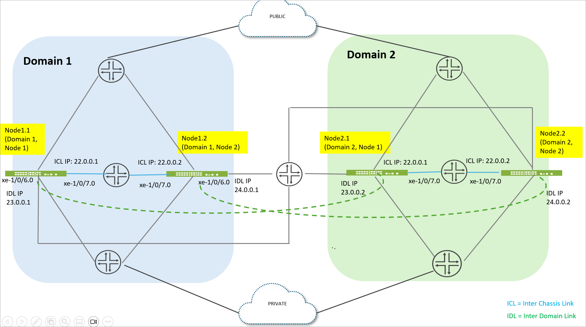
The topology represents a 4‑node Multinode High Availability (MNHA) design consisting of two independent domains: Domain 1 and Domain 2. Each domain contains two firewall nodes, providing redundancy and high availability within and across domains.
Domain 1 includes two firewalls: node1.1 (Domain 1, Node 1) and node1.2 (Domain 1, Node 2). Node1.1 is configured with an Inter‑Chassis Link (ICL) IP address of 22.0.0.1 and an Inter‑Domain Link (IDL) IP address of 23.0.0.1. Node1.2 uses an ICL IP address of 22.0.0.2 and an IDL IP address of 24.0.0.1. Together, these two nodes form a highly available pair within Domain 1.
Domain 2 also consists of two firewalls: node2.1 (Domain 2, Node 1) and node2.2 (Domain 2, Node 2). Node2.1 is assigned an ICL IP address of 22.0.0.1 and an IDL IP address of 23.0.0.2, while node2.2 uses an ICL IP address of 22.0.0.2 and an IDL IP address of 24.0.0.2. These two nodes form the high‑availability pair for Domain 2.
In this topology, specific interfaces are dedicated to interconnections. The interface xe‑1/0/7.0 is used for the Inter‑Chassis Link (ICL) within each domain, enabling synchronization and failover between the two nodes. The interface xe‑1/0/6.0 is used for the Inter‑Domain Link (IDL), which connects Domain 1 and Domain 2 to support domain‑level redundancy and continuity.
Following table provides sample configurations from all four nodes participating in the deployment. These examples show how each node defines its local identifiers, domain membership, peer relationships, and SRG associations to support synchronized redundancy across both MNHA domains.
By reviewing the configuration from each node’s perspective, you can clearly see how inter‑domain connectivity, cross‑node peering, and redundancy‑group coordination are structured to enable high availability in a multi‑domain, four‑node architecture.
| node1.1 (domain 1 node 1) | node2.1 (domain 2 node 1) |
|---|---|
user@host-node-1.1# show chassis high-availability
local-id {
    1;
    local-ip 22.0.0.1;
}
local-domain-id {
    1;
    domain-size 2;
}
peer-id 2 {
    peer-ip 22.0.0.2;
    interface xe-1/0/7.0;
    vpn-profile L3HA_IPSEC_VPN;
    liveness-detection {
        minimum-interval 500;
        multiplier 3;
    }
}
peer-domain-id 2 {
    domain-size 2;
    peer-id 1 {
        local-ip 23.0.0.1;
        peer-ip 23.0.0.2;
        interface xe-1/0/6.0;
        vpn-profile L3HA_IPSEC_VPN;
        liveness-detection {
            minimum-interval 500;
            multiplier 3;
        }
    }
}
services-redundancy-group 0 {
    peer-domain-id 2 {
        peer-id 1;
    }
    peer-id {
        2;
    }
}
|
user@host-node-2.1# show chassis high-availability
local-id {
    1;
    local-ip 22.0.0.1;
}
local-domain-id {
    2;
    domain-size 2;
}
peer-id 2 {
    peer-ip 22.0.0.2;
    interface xe-1/0/7.0;
    vpn-profile L3HA_IPSEC_VPN;
    liveness-detection {
        minimum-interval 500;
        multiplier 3;
    }
}
peer-domain-id 1 {
    domain-size 2;
    peer-id 1 {
        local-ip 23.0.0.2;
        peer-ip 23.0.0.1;
        interface xe-1/0/6.0;
        vpn-profile L3HA_IPSEC_VPN;
        liveness-detection {
            minimum-interval 500;
            multiplier 3;
        }
    }
}
services-redundancy-group 0 {
    peer-domain-id 1 {
        peer-id 1;
    }
    peer-id {
        2;
    }
}
|
| node1.2 (domain 1 node 2) | node2.2 (domain 2 node 2) (domain 2 node 2) |
user@host-node-1.2# show chassis high-availability
local-id {
    2;
    local-ip 22.0.0.2;
}
local-domain-id {
    1;
    domain-size 2;
}
peer-id 1 {
    peer-ip 22.0.0.1;
    interface xe-1/0/7.0;
    vpn-profile L3HA_IPSEC_VPN;
    liveness-detection {
        minimum-interval 500;
        multiplier 3;
    }
}
peer-domain-id 2 {
    domain-size 2;
    peer-id 2 {
        local-ip 24.0.0.1;
        peer-ip 24.0.0.2;
        interface xe-1/0/6.0;
        vpn-profile L3HA_IPSEC_VPN;
        liveness-detection {
            minimum-interval 500;
            multiplier 3;
        }
    }
}
services-redundancy-group 0 {
    peer-domain-id 2 {
        peer-id 2;
    }
    peer-id {
        1;
    }
}
|
user@host-node-2.2# show chassis high-availability
local-id {
    2;
    local-ip 22.0.0.2;
}
local-domain-id {
    2;
    domain-size 2;
}
peer-id 1 {
    peer-ip 22.0.0.1;
    interface xe-1/0/7.0;
    vpn-profile L3HA_IPSEC_VPN;
    liveness-detection {
        minimum-interval 500;
        multiplier 3;
    }
}
peer-domain-id 1 {
    domain-size 2;
    peer-id 2 {
        local-ip 24.0.0.2;
        peer-ip 24.0.0.1;
        interface xe-1/0/6.0;
        vpn-profile L3HA_IPSEC_VPN;
        liveness-detection {
            minimum-interval 500;
            multiplier 3;
        }
    }
}
services-redundancy-group 0 {
    peer-domain-id 1 {
        peer-id 2;
    }
    peer-id {
        1;
    }
}
|
After you configure the nodes, you must reboot all the nodes. Note that the system does not
display any warning message for rebooting the nodes. Log messages are displayed in
jsprd (Juniper Services Protocol Daemon) logs as shown
below:
domain_id]: Warning High Availability local domain id has changed, please reboot the device to avoid undesirable behavior
Dec 20 09:04:49 [jsrpd_ha_parse_local_domain_id]: Warning High Availability local domain size has changed, please reboot the device to avoid undesirable behavior
....
After you reboot the nodes, check status of MNHA to see if ICL and IDL status are showing as Up on all four nodes.
| Node1.1 (Domain 1 Node 1) | Node2.1 (Domain 2 Node 1) |
|---|---|
user@host-node-1.1> show chassis high-availability information
Dec 20 09:49:07
Node failure codes:
    HW  Hardware monitoring    LB  Loopback monitoring
    MB  Mbuf monitoring        SP  SPU monitoring
    CS  Cold Sync monitoring   SU  Software Upgrade

Node Status: ONLINE
Local-domain-id: 1
Local-id: 1

 Local-domain-info:
    ICL Local-IP: 22.0.0.1
    HA ICL Peer Information:

        Peer Id: 2        IP address: 22.0.0.2      Interface: xe-1/0/7.0
        Routing Instance: default
        Encrypted: YES    Conn State: UP
        Configured BFD Detection Time: 3 * 500ms
        Cold Sync Status: COMPLETE

 Peer-domain-info:
    Peer-domain-id: 2

        IDL Local-IP: 23.0.0.1
        HA IDL Peer Information:

            Peer Id: 1        IP address: 23.0.0.2      Interface: xe-1/0/6.0
            Routing Instance: default
            Encrypted: YES    Conn State: UP
            Configured BFD Detection Time: 3 * 500ms
            Cold Sync Status: COMPLETE

Services Redundancy Group: 0
        Current State: ONLINE
	Peer Information:
          Peer Id: 2
          Peer Domain Id: 2
             Peer Id: 1
|
user@host-node-2.2> show chassis high-availability information
Dec 20 09:53:18
Node failure codes:
    HW  Hardware monitoring    LB  Loopback monitoring
    MB  Mbuf monitoring        SP  SPU monitoring
    CS  Cold Sync monitoring   SU  Software Upgrade

Node Status: ONLINE
Local-domain-id: 2
Local-id: 1

 Local-domain-info:
    ICL Local-IP: 22.0.0.1
    HA ICL Peer Information:

        Peer Id: 2        IP address: 22.0.0.2      Interface: xe-1/0/7.0
        Routing Instance: default
        Encrypted: YES    Conn State: UP
        Configured BFD Detection Time: 3 * 500ms
        Cold Sync Status: COMPLETE

 Peer-domain-info:
    Peer-domain-id: 1

        IDL Local-IP: 23.0.0.2
        HA IDL Peer Information:

            Peer Id: 1        IP address: 23.0.0.1      Interface: xe-1/0/6.0
            Routing Instance: default
            Encrypted: YES    Conn State: UP
            Configured BFD Detection Time: 3 * 500ms
            Cold Sync Status: COMPLETE

Services Redundancy Group: 0
        Current State: ONLINE
	Peer Information:
          Peer Id: 2
          Peer Domain Id: 1
             Peer Id: 1
|
| Node1.2 (Domain 1 Node 2) | node2.2 (domain 2 node 2) |
user@host-node-1.2>  show chassis high-availability information
Node failure codes:
    HW  Hardware monitoring    LB  Loopback monitoring
    MB  Mbuf monitoring        SP  SPU monitoring
    CS  Cold Sync monitoring   SU  Software Upgrade

Node Status: ONLINE
Local-domain-id: 1
Local-id: 2

 Local-domain-info:
    ICL Local-IP: 22.0.0.2
    HA ICL Peer Information:

        Peer Id: 1        IP address: 22.0.0.1      Interface: xe-1/0/7.0
        Routing Instance: default
        Encrypted: YES    Conn State: UP
        Configured BFD Detection Time: 3 * 500ms
        Cold Sync Status: COMPLETE

 Peer-domain-info:
    Peer-domain-id: 2

        IDL Local-IP: 24.0.0.1
        HA IDL Peer Information:

            Peer Id: 2        IP address: 24.0.0.2      Interface: xe-1/0/6.0
            Routing Instance: default
            Encrypted: YES    Conn State: UP
            Configured BFD Detection Time: 3 * 500ms
            Cold Sync Status: COMPLETE

Services Redundancy Group: 0
        Current State: ONLINE
	Peer Information:
          Peer Id: 1
          Peer Domain Id: 2
             Peer Id: 2
|
user@host-node-2.2> show chassis high-availability information
Node failure codes:
    HW  Hardware monitoring    LB  Loopback monitoring
    MB  Mbuf monitoring        SP  SPU monitoring
    CS  Cold Sync monitoring   SU  Software Upgrade

Node Status: ONLINE
Local-domain-id: 2
Local-id: 2

 Local-domain-info:
    ICL Local-IP: 22.0.0.2
    HA ICL Peer Information:

        Peer Id: 1        IP address: 22.0.0.1      Interface: xe-1/0/7.0
        Routing Instance: default
        Encrypted: YES    Conn State: UP
        Configured BFD Detection Time: 3 * 500ms
        Cold Sync Status: COMPLETE

 Peer-domain-info:
    Peer-domain-id: 1

        IDL Local-IP: 24.0.0.2
        HA IDL Peer Information:

            Peer Id: 2        IP address: 24.0.0.1      Interface: xe-1/0/6.0
            Routing Instance: default
            Encrypted: YES    Conn State: UP
            Configured BFD Detection Time: 3 * 500ms
            Cold Sync Status: COMPLETE

Services Redundancy Group: 0
        Current State: ONLINE
	Peer Information:
          Peer Id: 1
          Peer Domain Id: 1
             Peer Id: 2
|
| Node1.1 (Domain 1 Node 1) | Node2.1 (Domain 2 Node 1) |
|---|---|
user@host-node-1.1> show chassis high-availability peer-info
Dec 20 10:07:45
HA ICL Peer Information:

    Peer Domain ID: 1
    Peer-ID: 2        IP address: 22.0.0.2      Interface: xe-1/0/7.0
    Routing Instance: default
    Encrypted: YES    Conn State: UP
    Cold Sync Status: COMPLETE
    Internal Interface: st0.16018
    Internal Local-IP: 180.17.18.17
    Internal Peer-IP: 180.17.18.18
    Internal Routing-instance: __juniper_private1__
Packet Statistics:
	Receive Error : 0        Send Error : 0

	Packet-type            Sent       Received
  	SRG Status Msg            0              0
  	SRG Status Ack            0              0
  	Attribute Msg             3              1
  	Attribute Ack             1              2
  	SRG Ctx Msg               4              6
  	SRG Ctx Ack               6              3
  	Pkt Req                   3              1
  	Pkt Req Ack               1              2

HA IDL Peer Information:

    Peer Domain ID: 2
    Peer-ID: 1        IP address: 23.0.0.2      Interface: xe-1/0/6.0
    Routing Instance: default
    Encrypted: YES    Conn State: UP
    Cold Sync Status: COMPLETE
    Internal Interface: st0.16033
    Internal Local-IP: 180.17.33.17
    Internal Peer-IP: 180.17.33.33
    Internal Routing-instance: __juniper_private1__

Packet Statistics:
	Receive Error : 0        Send Error : 0

	Packet-type            Sent       Received
  	SRG Status Msg            0              0
  	SRG Status Ack            0              0
  	Attribute Msg             2              1
  	Attribute Ack             1              1
  	SRG Ctx Msg               2              2
  	SRG Ctx Ack               2              1
  	Pkt Req                   2              1
  	Pkt Req Ack               1              1
|
user@host-node-2.1> show chassis high-availability peer-info
HA ICL Peer Information:

    Peer Domain ID: 1
    Peer-ID: 1        IP address: 22.0.0.1      Interface: xe-1/0/7.0
    Routing Instance: default
    Encrypted: YES    Conn State: UP
    Cold Sync Status: COMPLETE
    Internal Interface: st0.16017
    Internal Local-IP: 180.17.18.18
    Internal Peer-IP: 180.17.18.17
    Internal Routing-instance: __juniper_private1__
Packet Statistics:
	Receive Error : 0        Send Error : 0

	Packet-type            Sent       Received
  	SRG Status Msg            0              0
  	SRG Status Ack            0              0
  	Attribute Msg             4              2
  	Attribute Ack             2              1
  	SRG Ctx Msg               7              3
  	SRG Ctx Ack               3              6
  	Pkt Req                   3              2
  	Pkt Req Ack               2              1

HA IDL Peer Information:

    Peer Domain ID: 2
    Peer-ID: 2        IP address: 24.0.0.2      Interface: xe-1/0/6.0
    Routing Instance: default
    Encrypted: YES    Conn State: UP
    Cold Sync Status: COMPLETE
    Internal Interface: st0.16034
    Internal Local-IP: 180.18.34.18
    Internal Peer-IP: 180.18.34.34
    Internal Routing-instance: __juniper_private1__

Packet Statistics:
	Receive Error : 0        Send Error : 0

	Packet-type            Sent       Received
  	SRG Status Msg            0              0
  	SRG Status Ack            0              0
  	Attribute Msg             3              2
  	Attribute Ack             2              2
  	SRG Ctx Msg               4              3
  	SRG Ctx Ack               3              2
  	Pkt Req                   3              2
  	Pkt Req Ack               2              2
|
| Node1.2 (Domain 1 Node 2) | node2.2 (domain 2 node 2) |
user@host-node-1.2> show chassis high-availability peer-info
Dec 20 10:09:02
HA ICL Peer Information:

    Peer Domain ID: 2
    Peer-ID: 2        IP address: 22.0.0.2      Interface: xe-1/0/7.0
    Routing Instance: default
    Encrypted: YES    Conn State: UP
    Cold Sync Status: COMPLETE
    Internal Interface: st0.16034
    Internal Local-IP: 180.33.34.33
    Internal Peer-IP: 180.33.34.34
    Internal Routing-instance: __juniper_private1__
Packet Statistics:
	Receive Error : 0        Send Error : 0

	Packet-type            Sent       Received
  	SRG Status Msg            0              0
  	SRG Status Ack            0              0
  	Attribute Msg             4              3
  	Attribute Ack             3              3
  	SRG Ctx Msg              12              8
  	SRG Ctx Ack               8             11
  	Pkt Req                   4              3
  	Pkt Req Ack               3              3

HA IDL Peer Information:

    Peer Domain ID: 1
    Peer-ID: 1        IP address: 23.0.0.1      Interface: xe-1/0/6.0
    Routing Instance: default
    Encrypted: YES    Conn State: UP
    Cold Sync Status: COMPLETE
    Internal Interface: st0.16017
    Internal Local-IP: 180.17.33.33
    Internal Peer-IP: 180.17.33.17
    Internal Routing-instance: __juniper_private1__

Packet Statistics:
	Receive Error : 0        Send Error : 0

	Packet-type            Sent       Received
  	SRG Status Msg            0              0
  	SRG Status Ack            0              0
  	Attribute Msg             6              4
  	Attribute Ack             4              4
  	SRG Ctx Msg              11             13
  	SRG Ctx Ack              13              9
  	Pkt Req                   6              4
  	Pkt Req Ack               4              4
|
user@host-node-2.2> show chassis high-availability peer-info
Dec 20 10:09:09
HA ICL Peer Information:

    Peer Domain ID: 2
    Peer-ID: 1        IP address: 22.0.0.1      Interface: xe-1/0/7.0
    Routing Instance: default
    Encrypted: YES    Conn State: UP
    Cold Sync Status: COMPLETE
    Internal Interface: st0.16033
    Internal Local-IP: 180.33.34.34
    Internal Peer-IP: 180.33.34.33
    Internal Routing-instance: __juniper_private1__
Packet Statistics:
	Receive Error : 0        Send Error : 0

	Packet-type            Sent       Received
  	SRG Status Msg            0              0
  	SRG Status Ack            0              0
  	Attribute Msg             5              3
  	Attribute Ack             3              2
  	SRG Ctx Msg              11             11
  	SRG Ctx Ack              11              8
  	Pkt Req                   5              3
  	Pkt Req Ack               3              3

HA IDL Peer Information:

    Peer Domain ID: 1
    Peer-ID: 2        IP address: 24.0.0.1      Interface: xe-1/0/6.0
    Routing Instance: default
    Encrypted: YES    Conn State: UP
    Cold Sync Status: COMPLETE
    Internal Interface: st0.16018
    Internal Local-IP: 180.18.34.34
    Internal Peer-IP: 180.18.34.18
    Internal Routing-instance: __juniper_private1__

Packet Statistics:
	Receive Error : 0        Send Error : 0

	Packet-type            Sent       Received
  	SRG Status Msg            0              0
  	SRG Status Ack            0              0
  	Attribute Msg             4              3
  	Attribute Ack             3              3
  	SRG Ctx Msg               8             11
  	SRG Ctx Ack              11              7
  	Pkt Req                   4              3
  	Pkt Req Ack               3              3
|
Changes in show security flow session Command Output
Flow sessions include additional flags to identify the domain and node IDs. In the following samples, the session is initiated on Node 1.1, where it remains Active. It is then synchronized over the ICL to Node 1.2, where it is stored as a Warm session. The same session is also synchronized across the IDL to Node 2.1, where it is maintained as a Warm session. From there, it is further synchronized over the ICL to Node 2.2, where it is again stored in a Warm state.
Node1.1
user@host-node-1.1> show security flow session source-prefix 10.1.0.2
Dec 20 10:39:40
Session ID: 42949829103, Policy name: U_2_T/4, HA State: Active, Timeout: 295, Session State: Valid
  In: 10.1.0.2/10000 --> 10.6.0.2/20000;udp, Conn Tag: 0x0, If: et-1/0/0.0, Pkts: 40, Bytes: 47280, HA Wing State: Active,
  Out: 10.6.0.2/20000 --> 10.1.0.2/10000;udp, Conn Tag: 0x0, If: et-1/1/0.0, Pkts: 0, Bytes: 0, HA Wing State: Active,
  Active Domain Id: 1, Node Id: 1
Total sessions: 1
user@host-node-1.2> run show security flow session source-prefix 10.1.0.2
Dec 20 10:40:15
Session ID: 42949754770, Policy name: U_2_T/4, HA State: Warm, Timeout: 2337, Session State: Valid
  In: 10.1.0.2/10000 --> 10.6.0.2/20000;udp, Conn Tag: 0x0, If: et-1/0/0.0, Pkts: 0, Bytes: 0, HA Wing State: Warm,
  Out: 10.6.0.2/20000 --> 10.1.0.2/10000;udp, Conn Tag: 0x0, If: et-1/1/0.0, Pkts: 0, Bytes: 0, HA Wing State: Warm,
  Active Domain Id: 1, Node Id: 1
Total sessions: 1
user@host-node-2.1> show security flow session source-prefix 10.1.0.2
Dec 20 10:40:35
Session ID: 133148037485, Policy name: U_2_T/4, HA State: Warm, Timeout: 2316, Session State: Valid
  In: 10.1.0.2/10000 --> 10.6.0.2/20000;udp, Conn Tag: 0x0, If: et-1/0/0.0, Pkts: 0, Bytes: 0, HA Wing State: Warm,
  Out: 10.6.0.2/20000 --> 10.1.0.2/10000;udp, Conn Tag: 0x0, If: et-1/1/0.0, Pkts: 0, Bytes: 0, HA Wing State: Warm,
  Active Domain Id: 1, Node Id: 1
Total sessions: 1
user@host-node-2.2> show security flow session source-prefix 10.1.0.2
Dec 20 10:40:41
Session ID: 4298821580, Policy name: U_2_T/4, HA State: Warm, Timeout: 2308, Session State: Valid
  In: 10.1.0.2/10000 --> 10.6.0.2/20000;udp, Conn Tag: 0x0, If: et-1/0/0.0, Pkts: 0, Bytes: 0, HA Wing State: Warm,
  Out: 10.6.0.2/20000 --> 10.1.0.2/10000;udp, Conn Tag: 0x0, If: et-1/1/0.0, Pkts: 0, Bytes: 0, HA Wing State: Warm,
  Active Domain Id: 1, Node Id: 1
Total sessions: 1
Link Encryption with IPsec VPN
Link encryption ensures data privacy for all messages transmitted across the network. Because the ICL carries private data between HA nodes, it is essential to protect this link using encryption. The ICL is secured using IPsec VPN.
Similar to ICL protection, the Inter-Domain Link (IDL) encryption feature uses the IKEv2 protocol along with a custom implementation of multi‑SA to secure communication between HA nodes across domains. For IDL encryption, IPsec uses the external IP addresses assigned to each node, allowing the tunnel to be established between domain peers.
All traffic that requires protection between these nodes must be routed through the encrypted tunnel.
To encrypt the HA link for the IDL (similar to ICL):
- Install the Junos IKE package on your firewall by using the following command:
user@host> request system software add optional://junos-ike.tgz
- Configure a VPN profile for the HA traffic and apply the profile for both the nodes. The IPsec tunnel negotiated between the firewalls uses the IKEv2 protocol.
Ensure you have included the statement ha-link-encryption in your IPsec VPN configuration.
Example:user@host# set security ipsec vpn vpn-name ha-link-encryption
You can verify if the IDL links are encrypted using the following commands:
show security ike sa ha-link-encryptionuser@host-node-1.1> show security ike sa ha-link-encryption
Dec 20 11:34:10
Index State Initiator cookie Responder cookie Mode Remote Address
16776287 UP 66ae558ae33b709b 0d00c1db63d76739 IKEv2 22.0.0.2 >>ICL
16776288 UP 7138aa2b4d31e2a6 2c5cee6ea22312bf IKEv2 23.0.0.2 >>IDL
...
user@host-node-1.1> show security ipsec sa ha-link-encryption
Dec 20 11:35:10
  Total active tunnels: 2     Total IPsec sas: 80
  ID      Algorithm       SPI        Life:sec/kb     Mon    lsys Port  Gateway
  <495001 ESP:aes-gcm-256/aes256-gcm 0x0008782c 82 / unlim U root 500 22.0.0.2
  >495001 ESP:aes-gcm-256/aes256-gcm 0x00056a7b 82 / unlim U root 500 22.0.0.2
  <
...