Four-Node and Three-Node Multinode High Availability
Learn about the four-node and three-node Multinode High Availability solution.
For the list of supported features across different platforms and software releases, see Feature Explorer.
The four-node Multinode High Availability feature in Junos OS provides robust protection against service interruptions. The existing MNHA infrastructure supports redundancy with two firewalls functioning as a pair. Four-node MNHA enhance redundancy and failover capabilities by supporting additional redundancy between two pairs of MNHA devices across the domains. That is, if one pair of devices fails or goes offline, the other pair will automatically take over the services provided by the failed pair. The two pairs of devices can be located in different places, such as separate data centers, ensuring that services remain operational even if one location experiences issues.
Four-node MNHA features:
- SRG0 Support: Four-node MNHA support SRG0, which is suitable for services without control plane states, such as firewall and NAT. Control plane states refer to the information required to manage and control network operations.
- SRG1+ Limitations: Four-node MNHA currently does not support SRG1+ services, which involve control plane states, such as IPsec VPN.
- Operating Modes: Four-node MNHA support only the routing mode of MNHA. It will not include support for switching mode, hybrid mode, or cloud mode, which are different operational configurations for handling network traffic and redundancy.
-
Routing Limitations: The four-node MNHA infrastructure does not support asymmetric routing within the same domain or across two domains. Therefore, external routers must send packets of the same bidirectional flow to the same node consistently.
Benefits of four-node MNHA:
-
Provides enhanced service continuity. It allows seamless failover of services across nodes, ensuring uninterrupted uptime for critical network functions like firewalls and NAT without compromising control plane states.
-
Supports high availability across geographically distributed data centers, providing resilience against localized disruptions.
Deployment Scenario
The four-node MNHA setup involves four identical Junos firewalls, all having the same hardware configurations. These devices are organized into two MNHA domains, with each domain containing two firewalls.
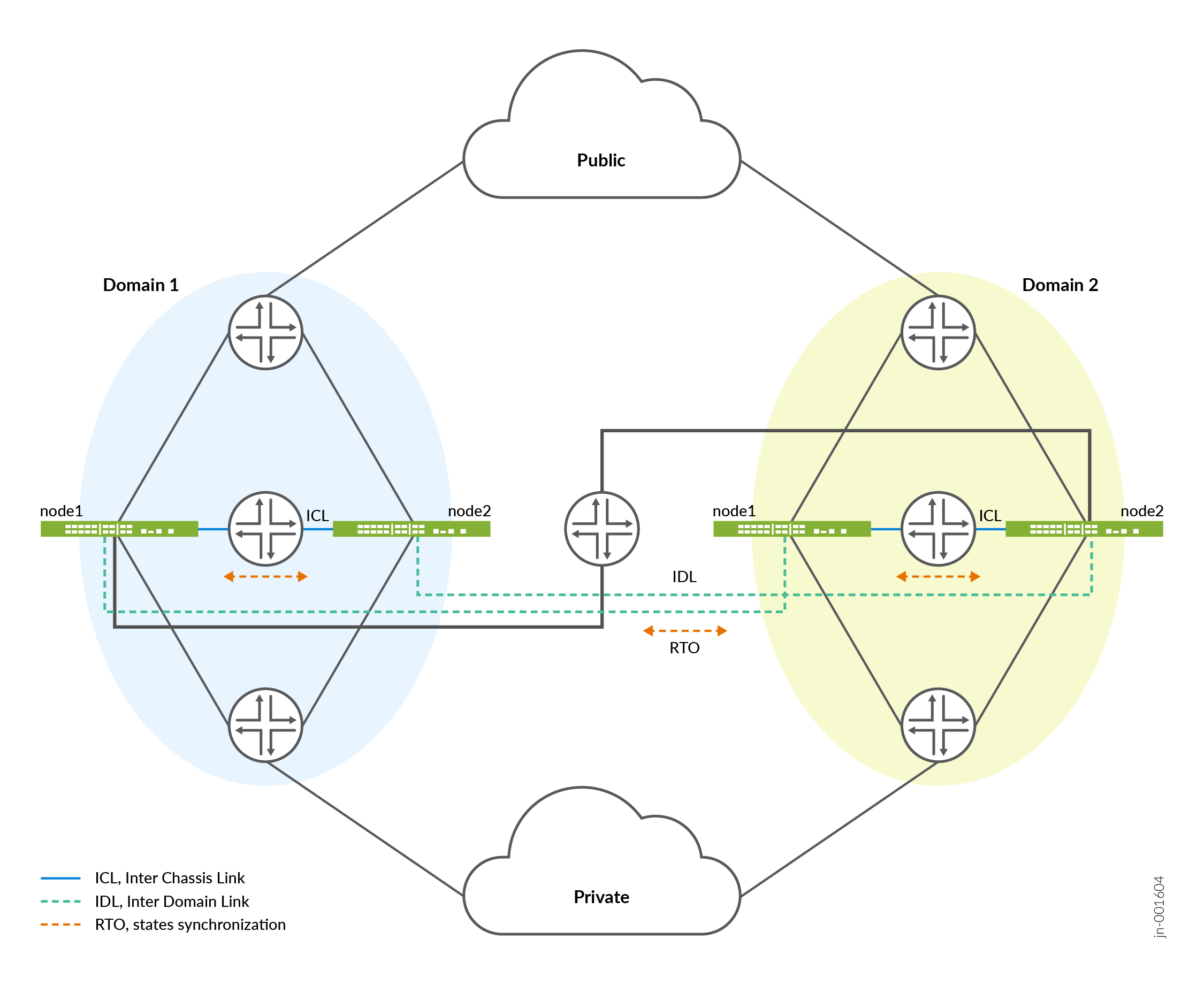
In the topology:
- Domain 1 consists of two firewalls— node1.1 (domain 1 node 1) and node1.2 (domain 1 node 2) .
- Domain 2 consists of two firewalls— node2.1 (domain 2 node 1) and node2.2 (domain 2 node 2) .
Inside each domain, the two nodes communicate through an Interchassis link (ICL), which is a direct connection that allows for fast and efficient communication. Across the two domains, the nodes communicate through inter-domain link (IDL). Both ICL and IDL are logical links, which can operate over dedicated interfaces or in-band traffic interfaces. Both ICL and IDL can be routed and use IPsec encryption.
IDL is a layer-three routable links that enable communication between nodes in different domains. Each IDL is configured on an interface of a node and is part of a private routing instance. This set up ensures that only internal communication packets between MNHA nodes across domains can traverse these links, maintaining security and integrity.
All four nodes are connected to external layer-three routers, which handle traffic from both public and private networks. This setup allows the Firewalls to manage network traffic efficiently.
To set up the four-node MNHA, we recommend first establish MNHA pairs within each domain by connecting two nodes through ICL. Then, connect these pairs (from different domains) through IDL to complete the full MNHA structure.
How Four-Node Multinode High Availability Works
The four-node MNHA architecture is structured into two domains, each consisting of two nodes. This setup enables redundancy at two levels: within a domain and across domains.
-
Within-Domain Redundancy:
- Each domain has two peer nodes that back each other up. If one node in the domain fails or is out of service, the other node takes over its responsibilities.
- The nodes within a domain can operate in two modes:
- Active-backup mode: One node is active, handling all tasks, while the other is on standby, ready to take over if the active node fails.
- Active-active mode: Both nodes are actively handling tasks, sharing the load, and providing immediate failover capabilities.
-
Across-Domain Redundancy:
- The nodes in one domain are backed up by nodes in the other domain. If all nodes in one domain fail, the nodes in the other domain take over the services.
- This redundancy also supports both active-backup and active-active modes, similar to the within-domain redundancy.
-
Communication and Synchronization:
- ICL: This is the communication link between the two nodes within the same domain. It allows them to synchronize their states and keep each other updated about their status.
- IDL: This newly introduced link facilitates communication between nodes across different domains, allowing them to synchronize states and share status information.
-
State Synchronization:
- Each node synchronizes its states with its peer in the same domain via the ICL.
- The node also synchronizes states with one of the nodes in the other domain via the IDL.
- When a node receives state information from another domain via the IDL,
it relays this information to its peer node in the same domain through
the ICL.
Example: In a setup shown in topology includes four nodes labeled node 1.1, node 1.2, node2.1, and node 2.2.
- Node 1.1 synchronizes its state with node 1.2 via ICL within the local domain.
- Node 1.1 also synchronizes with node 2.1 in the remote domain via IDL.
- Node 2.1, upon receiving this state, forwards it to node 2.2 in the same domain via ICL.
Cold-Synchronization in Four-Node MNHA
Cold Sync of states is a mechanism used in a network of interconnected nodes to ensure that all nodes have an up-to-date and consistent replica of states. When all nodes boot up, the nodes synchronize states within their domain, then proceed to synchronize across domains. If one node reboots, it will synchronize its states with a neighboring node in the same domain first, then continue synchronizing with nodes in remote domains to ensure it has all necessary states.
Following sequences are involved in cold-sync process in an MNHA setup:
-
Cold Sync Initiation:
Cold sync is initiated when a node needs to create or update its replica of states from its neighboring nodes in following scenarios:
- A node boots up and connects to other nodes.
- A node reconnects with its peer node in the same domain after a temporary disconnection (ICL flap).
- A node reconnects with its peer node in a remote domain after a temporary disconnection (IDL flap).
-
Cold Sync Process:
- Nodes are identified by domain ID and node ID. The node with the lower ID will initiate the cold sync by requesting states from the node with the higher ID.
- States include active states and any states received from remote
domains.
- Within the same domain: Nodes exchange states with each other via ICL based on their node IDs. The node with the lower ID requests states first.
- Across different domains: After completing cold sync within the same domain, nodes begin syncing across domains via IDL.
The process ensures that all nodes eventually have a complete and consistent set of states.
Software Upgrade in a Four-Node MNHA Setup
Use the following steps to upgrade software in a four-Node MNHA
- Ensure your Multinode High Availability setup is healthy, functional, and that the interchassis link (ICL) is up. This step is need to ensure that another node within the same domain is ready to take over the responsibilities of the node being upgraded.
-
Disconnect the inter-domain link (IDL) to isolate the node from the rest of the network, preventing any potential disruptions during the upgrade.
- Initiate the software upgrade process on the backup node (node 1.2) in domain 1
and commit the configuration using the
set chassis high-availability
                        software-upgrade
statement. - Confirm that the other device (node 1.1) is in an active role and is functioning normally.
- Install the Junos OS software on the node 1.2 and perform a reboot to apply the updates.
- Reboot the device using the
request system rebootorrequest vmhost rebootcommand (depending on your platform) after successful installation. - Check that the node is running the correct software version post-reboot using
the
show versioncommand. - Check status of the multinode high availability on the device.
- Remove the
software-upgradestatement on node 1.2 and commit the configuration. This steps enables the system to return to its normal operating mode. - Re-establish the inter-domain link to reintegrate the upgraded node into the network.
- Repeat the steps for the next node (node 1.1) within the same domain, ensuring each node is upgraded sequentially to maintain network stability.
- After completing upgrades in the current domain, move on to another domain (domain 2) and follow the same procedure to ensure a consistent and orderly upgrade process across the network.
Licensing and Topology Considerations
A four-node MNHA setup requires a specific four-node MNHA feature license. If the license is missing, the following warning appears during commit and in syslog:
License needed for the feature 4-node MNHA.
Licenses are unique to each firewall and cannot be shared between the nodes in a Multinode High Availability setup. Also ensure to use identical licenses for layer 7 capabilities such as AppID, IDP, Content Security on all four firewalls. If all four firewalls do not have an identical set of licenses, the system is not ready for the deployment.
Four-Node MNHA Configuration Requirements
In a Multinode high availability (MNHA) network setup, ensuring that sessions remain consistent across multiple nodes is crucial for maintaining seamless network operations and failover capabilities. Previously, there was a requirement that all nodes within an MNHA configuration had to use the same ingress and egress interface names, zone names, and policy names for a given session. This requirement could be challenging to meet, especially in a four-Node MNHA configuration, as it requires meticulous configuration management across all nodes.
The four-node MNHA relaxes some of these restrictions. Specifically, it removes the need for ingress and egress interfaces to have the same names across all nodes within the MNHA domain. This change means that while previously, the same session on different nodes had to use interfaces with identical names (such as ge-0/0/0 on all nodes), the new configuration allows these interfaces to have different names on each node.
Example: A session on node1.1 has ingress interface ge-0/0/0 and egress interface ge-0/0/1, when the same session is active on node 2.1 can have ingress interface ge-0/0/2 and egress interface ge-0/0/3. But, ge-0/0/0 and ge-0/0/2 should be in the same zone, and similarly ge-0/0/1 and ge-0/0/3 must be in a same zone.
You must meet the following requirements to ensure secure and reliable session handling
-
Zone consistency: The interfaces used for the same session on different nodes must belong to the same zone (as described in previous section).
-
Policy consistency: The policies applied to these zones must remain consistent across all nodes. This setting ensures that the security and routing behaviors remain the same, even if the physical interfaces differ.
-
Routing instances/VRF consistency: Similarly, VR names must remain the same across nodes to ensure consistent routing behavior.
Configuration Overview
The following configuration snippets outline the high-level steps required to set up a four-node MNHA system
- Local domain and node ID configuration:
-
Set the local domain ID and size:
user@host# set chassis high-availability local-domain-id <domain-id> domain-size <size>
domain-id: Unique identifier for the local domain (either 1 or 2).size: Number of nodes in the domain (1 or 2). For a four-node MNHA, domain size is 2.
-
Set the local node ID:
user@host# set chassis high-availability local-id <local-node-id>
local-node-id: Unique identifier for the local node within its domain (1 through 10).
-
- Inter-Chassis Link (ICL) configuration:
This configuration is for connecting the local node to a peer node within the same domain.
-
Set local node IP:
[edit]
user@host#  set chassis high-availability local-id local-ip <ip-address>
-
-
Peer node configuration:
[edit]
user@host# set chassis high-availability peer-id <peer-node-id> peer-ip <ip-address>
user@host# set chassis high-availability peer-id <peer-node-id> interface <logical-interface-name>
user@host# set chassis high-availability peer-id <peer-node-id> liveness-detection minimum-interval <interval-in-ms>
user@host# set chassis high-availability peer-id <peer-node-id> liveness-detection multiplier <multiplier-value>
user@host# set chassis high-availability peer-id <peer-node-id> vpn-profile IPSEC_VPN_ICL
- Inter-domain link (IDL) configuration: This configuration is for connecting
nodes across different domains.
user@host# set chassis high-availability peer-domain-id <domain-id> domain-size <size>
user@host# set chassis high-availability peer-domain-id <domain-id> peer-id <peer-node-id> local-ip <ip-address>
user@host# set chassis high-availability peer-domain-id <domain-id> peer-id <peer-node-id> peer-ip <ip-address>
user@host# set chassis high-availability peer-domain-id <domain-id> peer-id <peer-node-id> interface <logical-interface-name>
user@host# set chassis high-availability peer-domain-id <domain-id> peer-id <peer-node-id> liveness-detection minimum-interval <interval-in-ms>
user@host# set chassis high-availability peer-domain-id <domain-id> peer-id <peer-node-id> liveness-detection multiplier <multiplier-value>
user@host# set chassis high-availability peer-domain-id <domain-id> peer-id <peer-node-id> vpn-profile profile-name
- Service redundancy group (SRG0) configuration:
-
Set peer node in the same domain (1 through 10):
user@host# set chassis high-availability services-redundancy-group 0 peer-id 2
-
Set peer node in a different domain:
user@host# set chassis high-availability services-redundancy-group 0 peer-domain-id <domain-id> peer-id <peer-node-id>
Note: Ensure the following criteria is met:- Each domain ID must be unique and the ID can only be 1 or 2.
- Node IDs are unique within the same domain.
- The MNHA infrastructure supports four-node configurations
for SRG0 only if a
peer-domain-idis configured. Without it, the setup supports a 2-node configuration. - Reboot the device once you configure local domain ID, local node ID, peer domain ID, peer node ID, and domain size.
Use the commands such as
show chassis high-availability informationandshow chassis high-availability peer-infoto verify if your configuration is working as expected.
-
Inter-Domain Link (IDL) Encryption
Four-node Multinode High Availability (MNHA) with Inter-Domain Link (IDL) enhances high availability by extending it across data center domains. IDL facilitates communication between nodes across different domains, allowing the nodes to synchronize states and share status information.
IDL is a logical IP link and it is established using IP addresses that are routable in the network.
Nodes across the domains use the IDL to synchronize control plane and data plane states between them. IDL communication could go over a shared or untrusted network and packets sent over the IDL might traverse a path that is not always trusted. Therefore, you must secure the packets traversing the IDL by encrypting the traffic using IPsec standards.
IPsec protects traffic by establishing an encryption tunnel for the IDL. When you apply HA link encryption, the HA traffic flows between the nodes across the domains only through the secure, encrypted tunnel. Without HA link encryption, communication between the nodes might not be secure.
IDL supports IKEv2 and a custom Multi-SA implementation, to securely exchange encrypted data across domains through IPsec VPNs. The system supports robust AES-GCM-256 encryption and both PSK and PKI authentication, ensuring secure inter-domain communications.
Configuration Overview
To encrypt the HA link for the ICL:
- Install the Junos IKE package on your firewall by using the following
command:
user@host> request system software add optional://junos-ike.tgz
- Configure a VPN profile for the HA traffic and apply the profile for both
the nodes. The IPsec tunnel negotiated between the firewalls uses the IKEv2
protocol.
user@host# set chassis high-availability peer-domain-id domain-id peer-id peer-node-id vpn-profile
- Ensure you have included the statement ha-link-encryption in your IPsec VPN
configuration. Example:
user@host# set security ipsec vpn vpn-name ha-link-encryption.
- Verify the details using the
user@host> show security ipsec
                            statistics ha-link-encryption
command to display the tunnel type (ICL or IDL).
We recommend the following settings for an IDL:
- Use ports and network which is less likely to be saturated.
- Not to use the dedicated HA ports (control and fabric ports, if available on your firewall).
- You can use a revenue Ethernet port on the firewalls to setup an IDL connection. Ensure that you separate the transit traffic in revenue interfaces from the high availability (HA) traffic.
IPsec VPN Support in Four-Node Multinode High Availability Deployments
The four-node Multinode High Availability (MNHA) now supports SRG 1+ within each domain and adds domain-local IPsec tunnels. In a four-node MNHA setup that’s split into two domains, each IPsec VPN tunnel is local to its domain. This design enables a remote peer to set up separate redundant tunnels for each domain, so failover stays within that domain instead of affecting the whole setup.
Following illustration shows IPsec VPN Tunnels in a four-node MNHA setup.
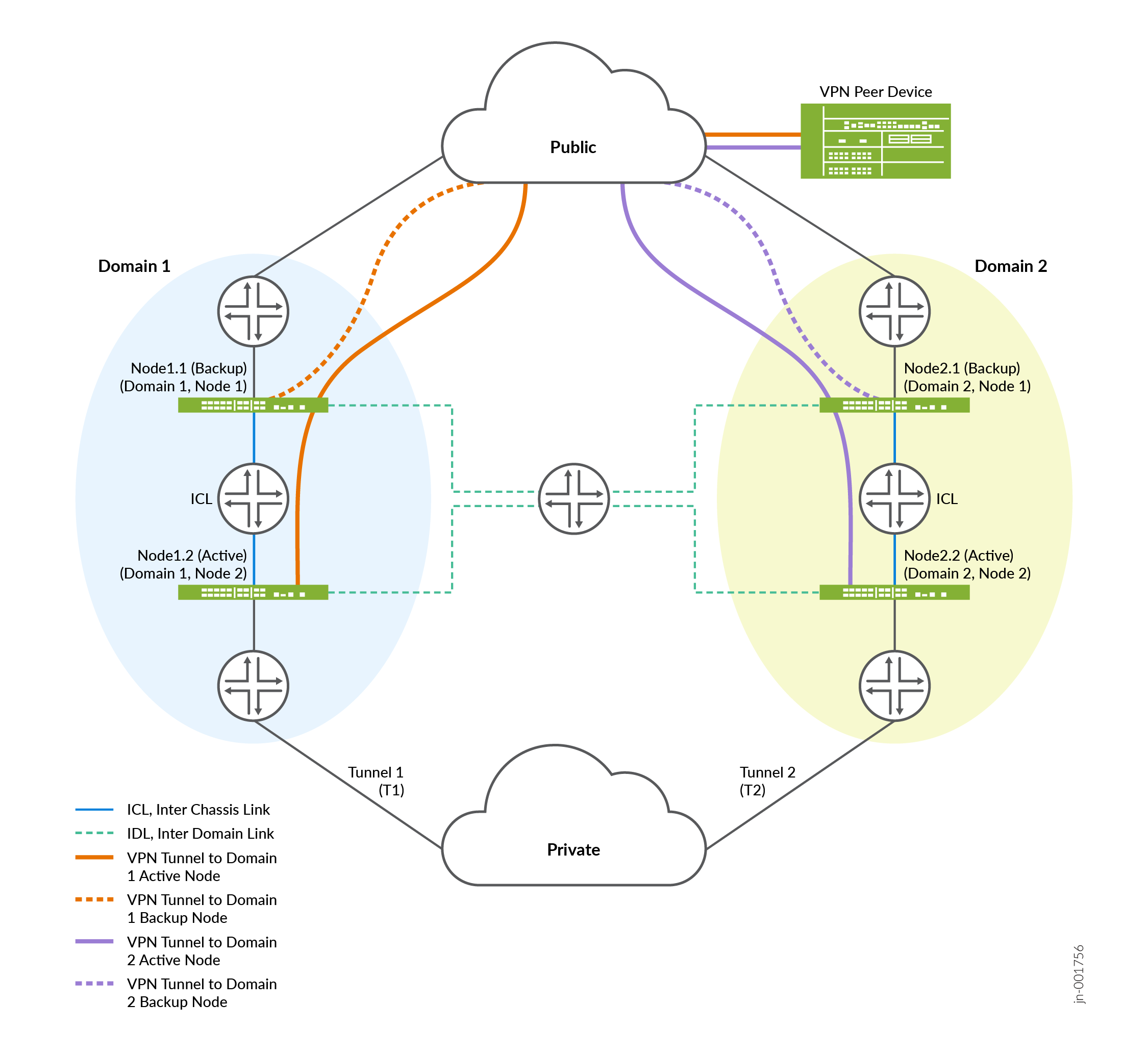
As shown in the topology, a VPN peer establishes one IPsec tunnel per domain. For example, Tunnel T1 terminates on Domain 1 and is synchronised to the backup node within Domain 1, while Tunnel T2 terminates on Domain 2 and is synchronised within Domain 2.
The peer device maintains a single tunnel towards each domain. The dotted line represents the backup IPsec tunnel, which is used during failover within the same domain. There is no cross-domain tunnel state sharing.
-
Tunnel terminates on active node.
- IPsec tunnel and SA state is synchronised across the ICL but not across the IDL.
-
Common loopback per domain can be used (and announced via dynamic routing, for example: BGP or OSPF) from each node to the upstream router to terminate the tunnel.
Within a domain, the active node establishes the IKE SAs and CHILD SAs with the peer and synchronises the tunnel control‑plane state only to the backup node in the same domain. Standby nodes in other domains do not receive or process state for tunnels they cannot assume ownership of. If a failure occurs within a domain, the backup node in that domain takes over using the locally synchronised tunnel state.
By default, when multiple domains are configured, IPsec VPN tunnels use domain-local scope, and their state is replicated only to backup nodes within the same domain. This design allows a remote peer to maintain independent tunnels per domain and ensures predictable, per‑domain failover behaviour.
Three-Node Multinode High Availability
The Three-Node MNHA setup involves three identical Junos Firewalls, all having the same hardware configurations. These devices are organized into two MNHA domains, with one domain containing two firewalls and another domain containing one firewall.
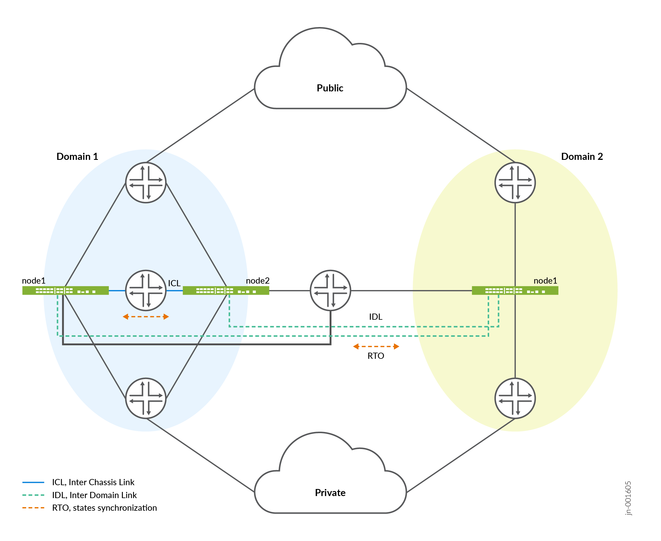
In a three-node MNHA setup, node 1.1 and node 1.2 belong to domain 1, while node 2.1 is in domain 2. For a four-node MNHA configuration, each node is equipped with one Inter-Cluster Link (ICL) and one Inter-Domain Link (IDL). In a three-node MNHA configuration, the two nodes in domain 1 each have one ICL and one IDL, whereas the node in domain 2 has two IDLs and no ICL.
State Synchronization
- In domain 1, Node 1.1 synchronizes its states with its peer (Node 1.2) through ICL.
- Node 1.1 also synchronizes states with Node 2.1 in the other domain through the IDL.
- Node 2.1 synchronizes states to Node 1.1 and Node 1.2 through IDL .
- When a node receives state information from another domain through the IDL, it does not relay this information to its peer node within the same domain via the ICL. This approach prevents unnecessary duplication of data transmission within the domain.
In the event of a single IDL failure—specifically, if the direct link between Node 1.1 and Node 2.1 is down—routing is employed to maintain connectivity. Node 1.1 can still communicate with Node 2.1 by using a predefined route through Node 1.2. This routing ensures that the IDL between Node 1.1 and Node 2.1 remains operational, eliminating the need for forwarding packets from IDL to ICL peers, whether for hot synchronize or cold sync processes.
Configuration Overview of Three-Node MNHA
In a three-node MNHA (Multinode High Availability) setup, devices are divided into two domains: one domain hosts two firewalls, and the other hosts a single firewall. The configuration snippet below demonstrates how to configure MNHA for the domain with a single node, focusing on local and peer node settings. Note that Inter-Chassis Link (ICL) configuration is not required for a single-node domain. The configuration for the other domain (domain with two nodes) is similar to the configuration for a four-node MNHA domain.
- Configure local ID, local domain ID, and domain size.
[edit]
user@host# set chassis high-availability local-id <local-node-id>
user@host# set chassis high-availability local-id local-ip <local-ip>
user@host# set chassis high-availability local-domain-id <domain-id>
user@host# set chassis high-availability local-domain-id domain-size 1
Domain size 1 indicates a domain that includes only one node in a three-node MNHA.
- Configure peer node.
[edit]
user@host# set chassis high-availability peer-domain-id 1 domain-size 2
- Configure IDL for peer-node 1.
[edit]
user@host# set chassis high-availability peer-domain-id 1 peer-id 1 local-ip <local-ip-address>
user@host# set chassis high-availability peer-domain-id 1 peer-id 1 peer-ip <peer-ip-address>
user@host# set chassis high-availability peer-domain-id 1 peer-id 1 interface <interface>
user@host# set chassis high-availability peer-domain-id 1 peer-id 1 vpn-profile <profile-name>
user@host# set chassis high-availability peer-domain-id 1 peer-id 1 liveness-detection minimum-interval <interval-in-ms>
user@host# set chassis high-availability peer-domain-id 1 peer-id 1 liveness-detection multiplier <multiplier-value>
- Configure IDL for peer-node 2.
[edit]
user@host# set chassis high-availability peer-domain-id 1 peer-id 2 local-ip <local-ip-address>
user@host# set chassis high-availability peer-domain-id 1 peer-id 2 peer-ip <peer-ip-address>
user@host# set chassis high-availability peer-domain-id 1 peer-id 2 interface <interface>
user@host# set chassis high-availability peer-domain-id 1 peer-id 2 vpn-profile <profile-name>
user@host# set chassis high-availability peer-domain-id 1 peer-id 2 liveness-detection minimum-interval <interval-in-ms>
user@host# set chassis high-availability peer-domain-id 1 peer-id 2 liveness-detection multiplier <multiplier-value>
- Configure service redundancy group.
[edit]
user@host# set chassis high-availability services-redundancy-group 0 peer-domain-id 1 peer-id 1
user@host# set chassis high-availability services-redundancy-group 0 peer-domain-id 1 peer-id 2
Use the commands such as show chassis high-availability
information and show chassis high-availability
peer-info to verify if your configuration is working as
expected.
Change History Table
Feature support is determined by the platform and release you are using. Use Feature Explorer to determine if a feature is supported on your platform.