ON THIS PAGE
SRX5800 Line Cards and Modules
SRX5400, SRX5600, and SRX5800 Firewall Card Overview
The cards described in this guide let you upgrade and customize your SRX5400, SRX5600, or SRX5800 Firewall to suit the needs of your network. The following types of cards are available for the SRX5400, SRX5600, and SRX5800 Firewalls:
I/O cards (IOCs) provide additional physical network connections to the firewall. Their primary function is to deliver data packets arriving on the physical ports to the Services Processing Cards (SPCs) and to forward data packets out the physical ports after services processing.
Flex IOCs have two slots for port modules that add additional physical network connections to the firewall. Like IOCs, their primary function is to deliver data packets arriving on the physical ports to the SPCs and to forward data packets out the physical ports after services processing.
Modular Port Concentrators (MPCs) have slots on the front panel that accept smaller cards called Modular Interface Cards (MICs). Each MIC has one or more physical interfaces on it. An MPC with MICs installed functions in the same way as a regular I/O card (IOC), but allows greater flexibility in adding different types of Ethernet ports to your firewall. MPCs and MICs are similar in form and function to Flex IOCs and port modules. However, the two use different form-factors, so you cannot install port modules in an MPC, nor can you install MICs in a Flex IOC.
Services Processing Cards (SPCs) provide the processing power to run integrated services such as firewall, IPsec and IDP. All traffic traversing the firewall is passed to an SPC to have services processing applied to it.
Switch Control Boards (SCBs) power on and power off IOCs and SPCs; control clocking and system resets; and control booting, monitor, and system functions. Each SCB has a slot in the front panel for a Routing Engine.
Although the following modules are not cards in the sense of having a form-factor that fits the card cage of the SRX5400, SRX5600, and SRX5800 Firewall, this guide also addresses the following modules that fit into certain SRX5400, SRX5600, and SRX5800 Firewall cards:
Routing Engines fit into slots in SCBs and maintain the routing tables, manage the routing protocols used on the device, control the device interfaces and some chassis components, and provide the interface for system management and user access to the device.
Port modules fit into slots in Flex IOCs and add additional physical network interface ports to the firewall.
Modular Interface Cards (MICs) fit into slots in MPCs and add additional physical network interface ports to the firewall. MPCs and MICs are similar in form and function to Flex IOCs and port modules. However, the two use different form-factors, so you cannot install port modules in an MPC, nor can you install MICs in a Flex IOC.
Cards Supported on SRX5400, SRX5600, and SRX5800 Firewalls
Table 1 describes the cards and other modules supported on the SRX5400, SRX5600, and SRX5800 Firewalls.
Card Name and Model Number |
Earliest Supported Junos OS Release |
Last Supported Junos OS Release |
|
|---|---|---|---|
SRX5400 |
SRX5600 and SRX5800 |
SRX5400, SRX5600, and SRX5800 |
|
| SPCs | |||
Not supported |
9.2 |
12.3X48 |
|
12.1X46-D10 |
12.1X44-D10 |
24.1 |
|
18.2R1-S1 |
18.2R1-S1 |
||
| Interface Cards | |||
Not supported |
9.2 |
12.3X48 |
|
Not supported |
9.2 |
12.3X48 |
|
Not supported |
10.2 |
12.3X48 |
|
12.1X46-D10 |
12.1X46-D10 |
21.4 |
|
15.1X49-D10 |
15.1X49-D10 |
||
15.1X49-D10 |
15.1X49-D10 |
||
19.3R1 |
19.3R1 |
||
19.3R1 |
19.3R1 |
||
| SCBs | |||
12.1X46-D10 |
9.2 |
12.3X48 |
|
12.1X47-D15 |
12.1X47-D15 |
||
15.1X49-D10 |
15.1X49-D10 |
||
Not supported |
19.3R1 |
||
| Other modules | |||
Not supported |
10.2 |
||
Not supported |
10.2 |
||
Not supported |
10.2 |
||
12.1X46-D10 |
12.1X46-D10 |
21.4 |
|
12.1X46-D10 |
12.1X46-D10 |
21.4 |
|
12.1X46-D10 |
12.1X46-D10 |
21.4 |
|
12.1X47-D10 |
12.1X47-D10 |
21.4 |
|
12.1X46-D10 |
9.2 |
12.3X48 |
|
12.1X47-D15 |
12.1X47-D15 |
21.4 |
|
19.3R1 |
19.3R1 |
||
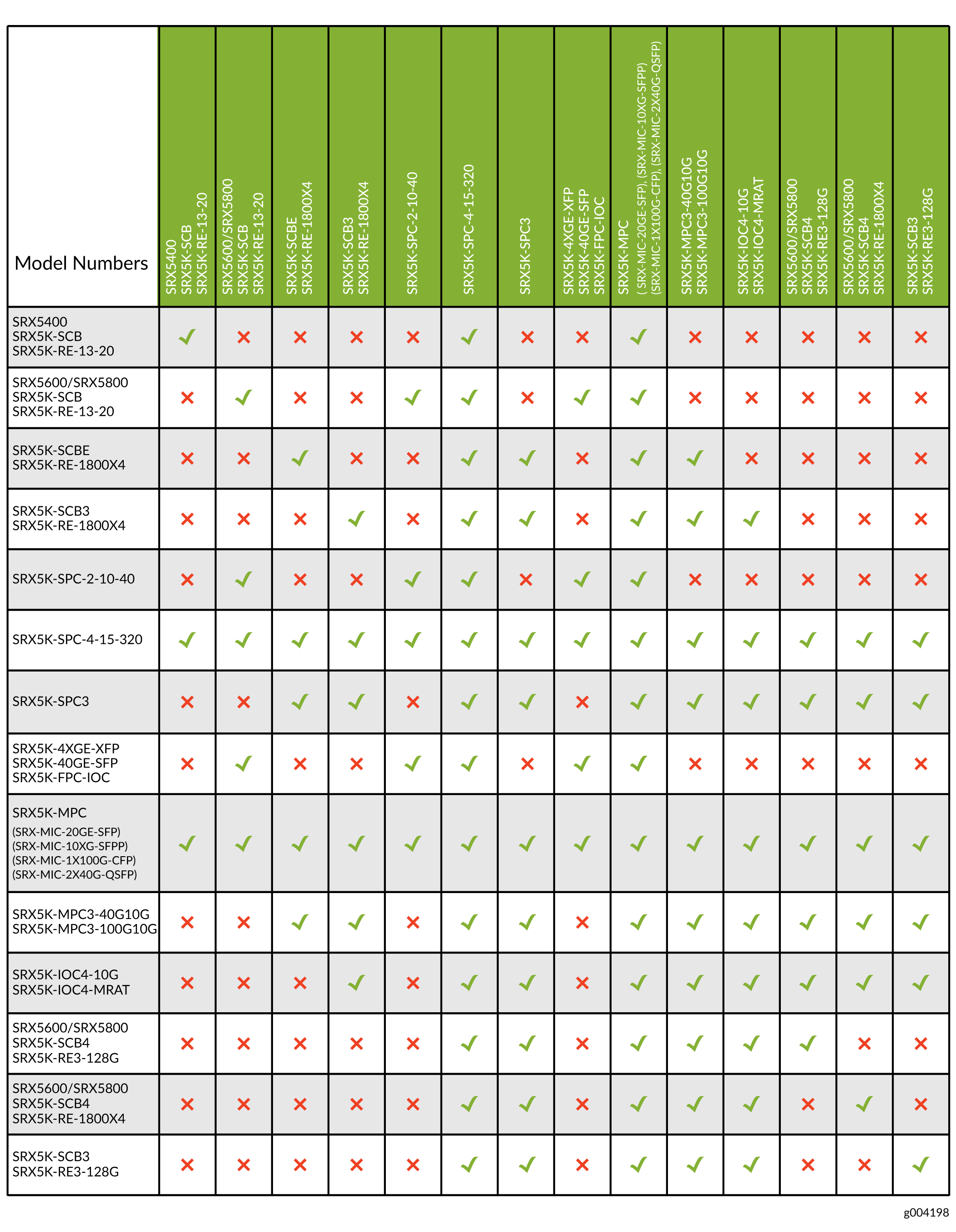
Figure 1 is an interoperability matrix that describes the compatibility between various interface cards for the SRX5400, SRX5600, and SRX5800 Firewalls.
SRX5800 Firewall Card Cage and Slots
The card cage is the set of 14 vertical slots in the front of the chassis where you install cards. The slots are numbered from left to right. Table 2 describes the types of cards that you can install into each slot.
Card Cage Slot |
Eligible Cards |
||||
|---|---|---|---|---|---|
SPC |
SPC3 |
IOC, Flex IOC, or MPC |
SCB |
IOC3 & IOC4 |
|
0 (leftmost) |
X |
X |
X |
||
1 |
X |
X |
X |
X |
|
2 |
X |
X |
X |
X |
|
3 |
X |
X |
X |
X |
|
4 |
X |
X |
X |
X |
|
5 |
X |
X |
X |
X |
|
0 |
X |
||||
1 |
X |
||||
2/6 |
X |
X |
X |
X |
X |
7 |
X |
X |
X |
X |
|
8 |
X |
X |
X |
X |
|
9 |
X |
X |
X |
X |
|
10 |
X |
X |
X |
X |
|
11 (rightmost) |
X |
X |
|||
For operational and cooling efficiency in SRX5800 Firewalls, we recommend that slot 0 and 11 be filled last.
SRX5800 Firewall SPC Description
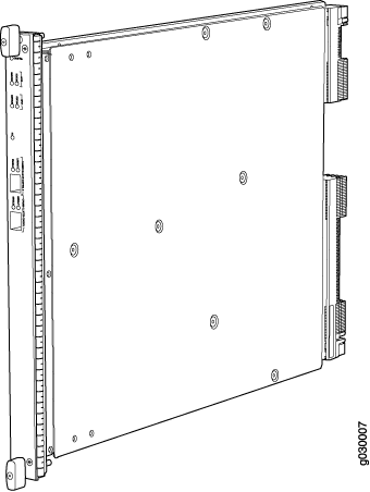
The Services Processing Card (SPC) has Services Processing Units (SPUs), which provide the processing power to run integrated services such as firewall, IPsec, and IDP (see Figure 2). All traffic traversing the firewall is passed to an SPU to have services processing applied to it. Traffic is intelligently distributed by interface cards to SPUs for services processing.
The firewall must have one SPC installed.
You can install an SPC in any of the slots that are not reserved for Switch Control Board (SCB). If a slot is not occupied by a card, you must install a blank panel to shield the empty slot and to allow cooling air to circulate properly through the device.
Figure 2 shows a typical SPC supported on the firewall.

For detailed information about SPCs supported by the firewall, see the SRX5400, SRX5600, and SRX5800 Firewall Card Reference at www.juniper.net/documentation/.
Services Processing Card SRX5K-SPC-2-10-40 Specifications
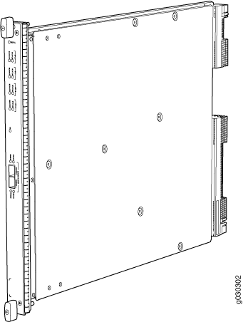
The SRX5K-SPC-2-10-40 Services Processing Card (SPC) contains two Services Processing Units (SPUs), which provide the processing power to run integrated services such as firewall, IPsec, and IDP (see Figure 3). All traffic traversing the firewall is passed to an SPU to have services processing applied to it. Traffic is intelligently distributed by I/O cards (IOCs) to SPUs for services processing.
The firewall must have at least one SPC installed. You can install additional SPCs to increase services processing capacity.
You can install SPCs in any of the slots that are not reserved for Switch Control Boards (SCBs). If a slot is not occupied by a card, you must install a blank panel to shield the empty slot and to allow cooling air to circulate properly through the device.
Figure 3 shows a typical SPC supported on the firewall.
Each SPC consists of the following components:
SPC cover, which functions as a ground plane and a stiffener.
Two small form-factor pluggable (SFP) chassis cluster control ports for connecting multiple devices into a redundant chassis cluster. See Chassis Cluster User Guide for SRX Series Devices for more information about connecting and configuring redundant chassis clusters.
CAUTION:The Juniper Networks Technical Assistance Center (JTAC) provides complete support for Juniper-supplied optical modules and cables. However, JTAC does not provide support for third-party optical modules and cables that are not qualified or supplied by Juniper Networks. If you face a problem running a Juniper device that uses third-party optical modules or cables, JTAC may help you diagnose host-related issues if the observed issue is not, in the opinion of JTAC, related to the use of the third-party optical modules or cables. Your JTAC engineer will likely request that you check the third-party optical module or cable and, if required, replace it with an equivalent Juniper-qualified component.
Use of third-party optical modules with high-power consumption (for example, coherent ZR or ZR+) can potentially cause thermal damage to or reduce the lifespan of the host equipment. Any damage to the host equipment due to the use of third-party optical modules or cables is the users’ responsibility. Juniper Networks will accept no liability for any damage caused due to such use.
Fabric interfaces.
Two Gigabit Ethernet interfaces that allow control information, route information, and statistics to be sent between the Routing Engine and the CPU on the SPCs.
Two interfaces from the SCBs that enable the boards to be powered on and controlled.
Physical SPC connectors.
Midplane connectors and power circuitry.
Processor subsystem, which includes a 1.2-GHz CPU, system controller, and 1 GB of SDRAM.
LEDs on the faceplate that indicate the SPC and SPU status.
Description |
SPC with two SPUs |
Software release |
|
Cables and connectors |
CHASSIS CLUSTER CONTROL 0 and CHASSIS CLUSTER CONTROL 1–SFP ports for control links in chassis cluster configurations. Supported SFP transceivers: 1000BASE-LH (model numbers SRX-SFP-1GE-LH, SRX-SFP-1GE-LH-ET) 1000BASE-LX (model numbers SRX-SFP-1GE-LX, SRX-SFP-1GE-LX-ET) 1000BASE-SX (model numbers SRX-SFP-1GE-SX, SRX-SFP-1GE-SX-ET) |
Controls |
None |
Supported Slots |
|
Power Requirement |
Maximum 265 W |
Weight |
Approximately 13 lb (5.9 kg) |
LEDs |
OK/FAIL LED, one bicolor:
STATUS LED, one tricolor for each of the two SPUs SPU 0 and SPU 1:
SERVICE LED, one bicolor for each of the two SPUs, SPU 0 and SPU 1:
HA LED, one tricolor: Note:
The HA LED is lit only if the SPC has a control link, otherwise it is off. Sometimes even after the control link is removed from the SPC, the HA LED would lit. Power cycle both the nodes to turn off the LED,
LINK/ACT LED, one for each of the two ports CHASSIS CLUSTER CONTROL 0 and CHASSIS CLUSTER CONTROL 1:
ENABLE LED, one for each of the two ports CHASSIS CLUSTER CONTROL 0 and CHASSIS CLUSTER CONTROL 1:
|
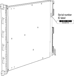
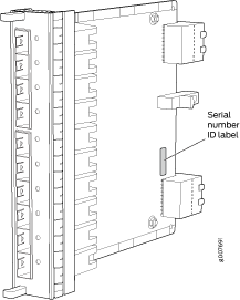
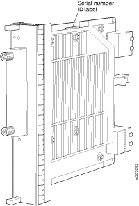
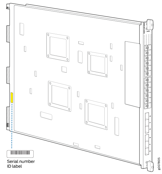
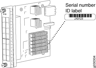
Serial Number Location |
The serial number label is located as shown in Figure 4. Figure 4: Serial Number Label (IOC Shown, Other
Cards Similar)
 |
Services Processing Card SRX5K-SPC-4-15-320 Specifications
The SRX5K-SPC-4-15-320 Services Processing Card (SPC) contains four Services Processing Units (SPUs), which provide the processing power to run integrated services such as firewall, IPsec, and IDP (see Figure 5). All traffic traversing the firewall is passed to an SPU to have services processing applied to it. Traffic is intelligently distributed by I/O cards (IOCs) to SPUs for services processing.
The firewall must have at least one SPC installed. You can install additional SPCs to increase services processing capacity.
You can install SPCs in any of the slots that are not reserved for Switch Control Boards (SCBs). If a slot is not occupied by a card, you must install a blank panel to shield the empty slot and to allow cooling air to circulate properly through the device.
If your firewall contains a mix of SRX5K-SPC-4-15-320 SPCs and earlier SRX5K-SPC-2-10-40 SPCs, an SRX5K-SPC-4-15-320 SPC must occupy the lowest-numbered slot of any SPC in the chassis. This configuration ensures that the center point (CP) function is performed by the faster and higher-performance SPC type.
Each SPC consists of the following components:
SPC cover, which functions as a ground plane and a stiffener.
Two small form-factor pluggable (SFP) chassis cluster control ports for connecting multiple devices into a redundant chassis cluster. See Chassis Cluster User Guide for SRX Series Devices for more information about connecting and configuring redundant chassis clusters.
CAUTION:The Juniper Networks Technical Assistance Center (JTAC) provides complete support for Juniper-supplied optical modules and cables. However, JTAC does not provide support for third-party optical modules and cables that are not qualified or supplied by Juniper Networks. If you face a problem running a Juniper device that uses third-party optical modules or cables, JTAC may help you diagnose host-related issues if the observed issue is not, in the opinion of JTAC, related to the use of the third-party optical modules or cables. Your JTAC engineer will likely request that you check the third-party optical module or cable and, if required, replace it with an equivalent Juniper-qualified component.
Use of third-party optical modules with high-power consumption (for example, coherent ZR or ZR+) can potentially cause thermal damage to or reduce the lifespan of the host equipment. Any damage to the host equipment due to the use of third-party optical modules or cables is the users’ responsibility. Juniper Networks will accept no liability for any damage caused due to such use.
Fabric interfaces.
Two Gigabit Ethernet interfaces that allow control information, route information, and statistics to be sent between the Routing Engine and the CPU on the SPCs.
Two interfaces from the SCBs that enable the boards to be powered on and controlled.
Physical SPC connectors.
Midplane connectors and power circuitry.
Processor subsystem, which includes a 1.2-GHz CPU, system controller, and 1 GB of SDRAM.
LEDs on the faceplate that indicate the SPC and SPU status.
Description |
SPC with four SPUs |
Software release |
|
Cables and connectors |
CHASSIS CLUSTER CONTROL 0 and CHASSIS CLUSTER CONTROL 1–SFP ports for control links in chassis cluster configurations. Supported SFP transceivers: 1000BASE-LH (model numbers SRX-SFP-1GE-LH, SRX-SFP-1GE-LH-ET) 1000BASE-LX (model numbers SRX-SFP-1GE-LX, SRX-SFP-1GE-LX-ET) 1000BASE-SX (model numbers SRX-SFP-1GE-SX, SRX-SFP-1GE-SX-ET) |
Controls |
None |
Supported Slots |
|
Power Requirement |
475 W typical, 585 W maximum Note:
|
Weight |
Approximately 18 lb (8.3 kg) |
LEDs |
OK/FAIL LED, one bicolor:
STATUS LED, one tricolor for each of the four SPUs SPU 0 through SPU 3:
SERVICE LED, one bicolor for each of the four SPUs SPU 0 through SPU 3:
HA LED, one tricolor:
LINK/ACT LED, one for each of the two ports CHASSIS CLUSTER CONTROL 0 and CHASSIS CLUSTER CONTROL 1:
ENABLE LED, one for each of the two ports CHASSIS CLUSTER CONTROL 0 and CHASSIS CLUSTER CONTROL 1:
|
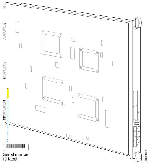
Serial Number Location |
The serial number label is located as shown in Figure 6. Figure 6: Serial Number Label (IOC Shown, Other
Cards Similar)
|
Services Processing Card SRX5K-SPC3 Specifications
The SRX5K-SPC3 Services Processing Card (SPC) contains two Services Processing Units (SPUs) with 128GB of memory per SPU, that provide the processing power to run integrated services such as firewall, IPsec, and IDP (see Figure 7). All traffic traversing the firewall is passed to an SPU to have services processing applied to it. Traffic is intelligently distributed by I/O cards (IOCs) to SPUs for services processing.
The firewall must have at least one SPC installed. You can install additional SPCs to increase services processing capacity.
SRX5K-SPC3 cannot be installed in slots that are reserved for Switch Control Boards (SCBs) or in slot 11 on the SRX5800. If a slot is not occupied by a card, you must install a blank panel to shield the empty slot and to allow cooling air to circulate properly through the device.
Your firewall cannot have a mix of SRX5K-SPC-2-10-40 SPCs and SRX5K-SPC3 SPCs. Starting with Junos OS release 18.2R2 and then 18.4R1 but not 18.3R1, you can have a mix of SRX5K-SPC-4-15-320 SPCs and SRX5K-SPC3 SPCs.
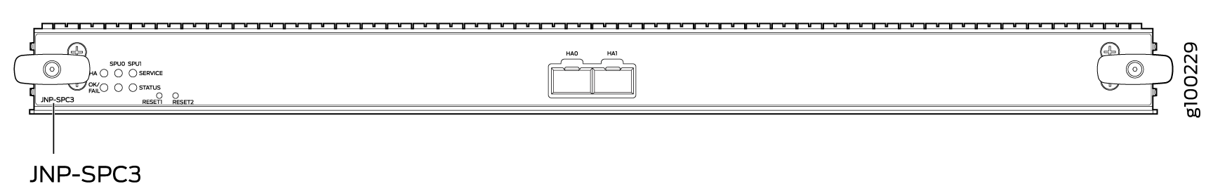
Each SPC consists of the following components:
SPC cover, which functions as a ground plane and a stiffener.
Two 10–Gigabit Ethernet small form-factor pluggable plus (SFP+) chassis cluster control ports for connecting multiple devices into a redundant chassis cluster. See the Chassis Cluster User Guide for SRX Series Devices for more information about connecting and configuring redundant chassis clusters.
CAUTION:The Juniper Networks Technical Assistance Center (JTAC) provides complete support for Juniper-supplied optical modules and cables. However, JTAC does not provide support for third-party optical modules and cables that are not qualified or supplied by Juniper Networks. If you face a problem running a Juniper device that uses third-party optical modules or cables, JTAC may help you diagnose host-related issues if the observed issue is not, in the opinion of JTAC, related to the use of the third-party optical modules or cables. Your JTAC engineer will likely request that you check the third-party optical module or cable and, if required, replace it with an equivalent Juniper-qualified component.
Use of third-party optical modules with high-power consumption (for example, coherent ZR or ZR+) can potentially cause thermal damage to or reduce the lifespan of the host equipment. Any damage to the host equipment due to the use of third-party optical modules or cables is the users’ responsibility. Juniper Networks will accept no liability for any damage caused due to such use.
Fabric interfaces
One Gigabit Ethernet switch that provides control connectivity to the Routing Engine.
Two interfaces from the SCBs that enable the boards to be powered on and controlled.
Physical SPC connectors
Midplane connectors and power circuitry.
Processor subsystem, which includes a 2.3-GHz CPU, system controller, and two 128 GB solid state-drives (SSDs).
LEDs on the faceplate that indicate the SPC and SPU status.
Description |
SPC with two SPUs of 256 GB memory. |
Software release |
|
Cables and connectors |
HA0 and HA1 SFP+ ports for control links in chassis cluster configurations. Supported transceivers:
|
Controls |
None |
Supported Slots |
|
Power Requirement |
650 W maximum Note:
|
Weight |
Approximately 18 lb (8.3 kg) |
LEDs |
OK/FAIL LED, one bicolor:
STATUS LED, one tricolor for each SPU SPU 0 and SPU 1:
SERVICE LED, one tricolor for each SPU SPU 0 and SPU 1:
HA LED, one tricolor:
LINK/ACT LED, one for each of the two ports CHASSIS CLUSTER CONTROL 0 and CHASSIS CLUSTER CONTROL 1:
|
Modular Port Concentrator (SRX5K-MPC) Specifications
The SRX5K-MPC (see Figure 8) is an interface card with two slots that accept MICs. These MICs add Ethernet ports to your firewall. An MPC with MICs installed functions in the same way as a regular IOC but allows you to add different types of Ethernet ports to your firewall. MPCs and MICs are similar in form and function to Flex IOCs and port modules. However, the two use different form-factors, so you cannot install port modules in an MPC, nor can you install MICs in a Flex IOC.
You must install at least one interface card in the firewall. The interface card can be of any of the available IOC, Flex IOC, or MPC types. You can add just one MIC; or you can add two MICs of the same or different types.
You can install MPCs in any of the slots that are not reserved for Switch Control Boards (SCBs).
If a slot in the SRX5400, SRX5600, or SRX5800 Firewall card cage is not occupied by a card, you must install a blank panel to shield the empty slot and to allow cooling air to circulate properly through the firewall. If a slot in an MPC is not occupied by a MIC, you must install a blank panel in the empty MIC slot to shield it and to allow cooling air to circulate properly through the MPC.
When installing an SRX5K-MPC in an SRX5600 or SRX5800 Firewall:
If the
session-distribution-modehas not been explicitly configured using the CLI command:user@host set security forwarding-process application-services session-distribution-modeThe SRX5K-MPC defaults to hash-based mode automatically even if existing SRX5K-MPC or non-MPCs are installed. You cannot set the
session-distribution-modetonormal.If the
session-distribution-modehas been explicitly configured tonormal, and the MIC is installed in the device, then the SRX5K-MPC will remain offline, and the firewall generates a major alarm and logs the event for troubleshooting. You must explicitly configure thesession-distribution-modeusing the CLI command:user@host set security forwarding-process application-services session-distribution-mode hash-based
When installing an SRX5K-MPC in an SRX5400 Firewall, the
session-distribution-mode will only function when
hash-based mode is configured or set as the default. The normal
mode is not supported.
A 9% drop is observed for PPS (throughput) when moving from session mode to hash mode (for SRX5K-MPC or non-MPCs), whereas no drop in performance is observed on CPS (connection per second) and session capacity numbers.
For more information about the CLI command, see the Junos OS documentation at www.juniper.net/documentation/.
Description |
|
Software release |
Junos OS Release 12.1x46-D10 |
Cables and connectors |
Slots for two MICs |
Controls |
One ejector knob each for MIC slots 0 and 1. Pull the ejector knob to unseat and partially eject the adjacent MIC. |
Supported slots |
|
Power requirement |
Maximum of 570 W for the MPC with two MICs, including applicable transceivers. Note:
|
Weight |
Approximately 10 lb (4.5 kg) without MICs |
LEDs |
OK/FAIL LED, one bicolor:
|
Serial number location |
The serial number label is yellow and is located on the opposite side of the card. |
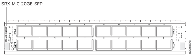
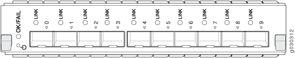
MIC with 20x1GE SFP Interfaces (SRX-MIC-20GE-SFP)
You use Modular Interface Cards (MICs) and Modular Port Concentrators (MPCs) to add different combinations of Ethernet interfaces to your firewall to suit the specific needs of your network.
The SRX-MIC-20GE-SFP MIC (see Figure 9) can be installed in the SRX-5K MPC to add twenty 1-Gigabit Ethernet small form-factor pluggable (SFP) Ethernet ports.
Description |
|
Software release |
Junos OS Release 12.1X47-D10 |
Cables and connectors |
Sockets for 20 SFP Gigabit Ethernet transceivers. Supported SFP transceivers: 1000BASE-LX (model numbers SRX-SFP-1GE-LX, SRX-SFP-1GE-LX-ET) 1000BASE-SX (model numbers SRX-SFP-1GE-SX, SRX-SFP-1GE-SX-ET) 1000BASE-T (model numbers SRX-SFP-1GE-T, SRX-SFP-1GE-T-ET) |
Weight |
Approximately 1.2 lb (0.54 kg) |
LEDs |
OK/FAIL LED, one bicolor:
LINK LED, single color, one per SFP port:
|
Port and Interface Numbering |
Each MPC accepts up to two MICs. SRX-MIC-20GE-SFP is a 20-port Gigabit Ethernet MIC with SFP. Each port on a MIC corresponds to a unique interface name in the CLI. In the syntax of an interface name, a hyphen (
Figure 10 shows the SRX-MIC-20GE-SFP MIC installed in slot 0 of an
MPC in slot Figure 10: SRX-MIC-20GE-SFP Interface Port Mapping
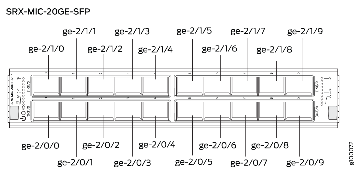 The SRX-MIC-20GE-SFP MIC contains two logical PICs, numbered The sample output of the The logical PICs of the two MICs— user@host> show chassis hardware
node1:
--------------------------------------------------------------------------
Slot 1 Online SRX5k SPC II
PIC 0 Online SPU Cp
PIC 1 Online SPU Flow
PIC 2 Online SPU Flow
PIC 3 Online SPU Flow
Slot 2 Online SRX5k IOC II
PIC 0 Online 10x 1GE(LAN) SFP
PIC 1 Online 10x 1GE(LAN) SFP
PIC 2 Online 10x 1GE(LAN) SFP
PIC 3 Online 10x 1GE(LAN) SFP
{primary:node1}
The user@host> show interfaces terse Interface Admin Link Proto Local Remote gr-0/0/0 up up ip-0/0/0 up up lt-0/0/0 up up ge-2/0/0 up up ge-2/0/1 up down ge-2/0/2 up down ge-2/0/3 up down ge-2/0/4 up down ge-2/0/5 up up ge-2/0/6 up down ge-2/0/7 up down ge-2/0/8 up up ge-2/0/9 up up ge-2/1/0 up down ge-2/1/1 up up ge-2/1/2 up down ge-2/1/3 up down ge-2/1/4 up up ge-2/1/5 up down ge-2/1/6 up down ge-2/1/7 up down ge-2/1/8 up up ge-2/1/9 up up ge-2/2/0 up down ge-2/2/1 up down ge-2/2/2 up down ge-2/2/3 up down ge-2/2/4 up down ge-2/2/5 up down ge-2/2/6 up down ge-2/2/7 up down ge-2/2/8 up down ge-2/2/9 up down ge-2/3/0 up down ge-2/3/1 up down ge-2/3/2 up down ge-2/3/3 up down ge-2/3/4 up down ge-2/3/5 up down ge-2/3/6 up down ge-2/3/7 up down ge-2/3/8 up down ge-2/3/9 up down |
Serial number location |
The serial number label is yellow and is located as shown in Figure 11. Figure 11: SRX-MIC-20GE-SFP Serial Number
Label
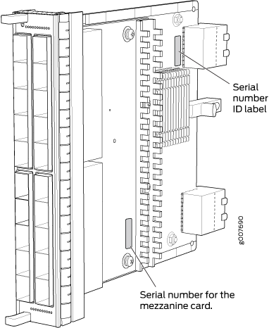 Note:
The serial number for the mezzanine card is shown only for reference and is never used for any purpose. |
MIC with 10x10GE SFP+ Interfaces (SRX-MIC-10XG-SFPP)
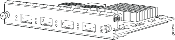
You use MICs and MPCs to add different combinations of Ethernet interfaces to your firewall to suit the specific needs of your network. The SRX-MIC-10XG-SFPP (see Figure 12) can be installed in an MPC to add ten 10-Gigabit Ethernet SFP+ ports.
Description |
|
Software release |
Junos OS Release 12.1X46-D10 |
Cables and connectors |
Sockets for ten 10-Gbps SFP+ transceivers See Hardware Compatibility Tool for the transceivers supported. |
Supported slots |
Either slot in SRX5K-MPC |
Weight |
Approximately 1.6 lb (0.7 kg) |
LEDs |
OK/FAIL LED, one bicolor:
LINK LED, single color:
|
Port and Interface Numbering |
Each port on a MIC corresponds to a unique interface name in the CLI. In the syntax of an interface name, a hyphen (
Figure 13 shows the port and interface numbering of an SRX-MIC-10XG-SFPP MIC when it is
installed in slot 0 of an MPC in slot Figure 13: SRX-MIC-10XG-SFPP Port and Interface Numbering
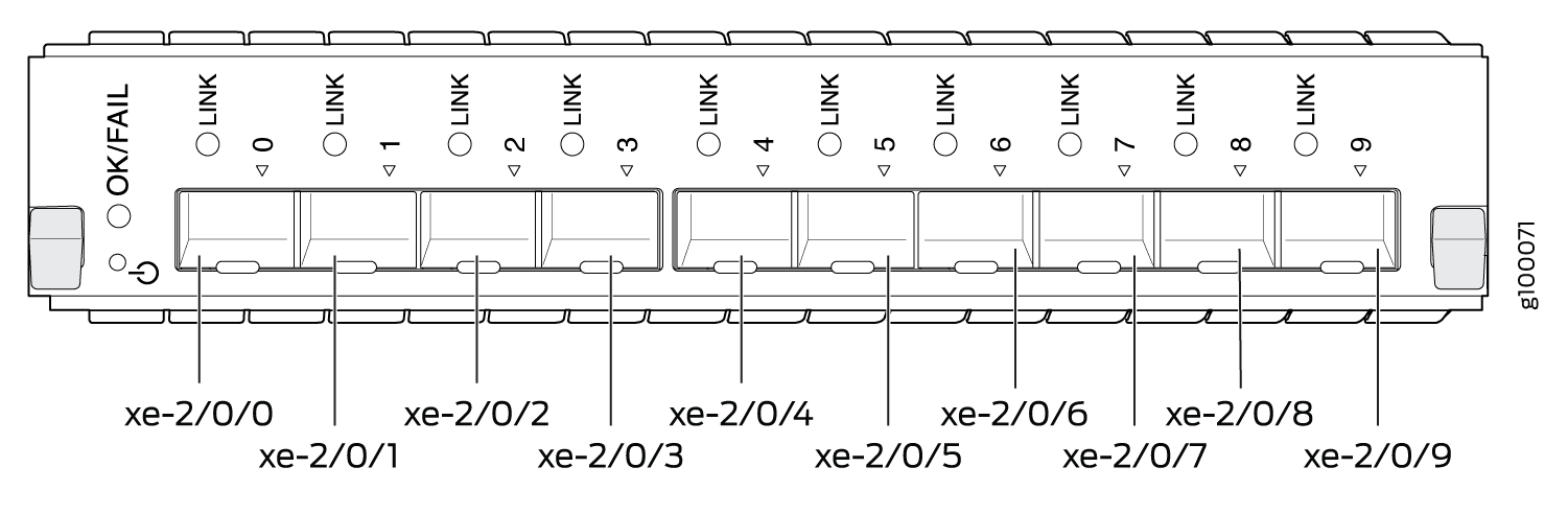 The SRX-MIC-10XG-SFPP MIC contains one logical PIC, numbered The sample output of the The logical PICs of the two MICs— user@host> show chassis fpc pic-status Slot 1 Online SRX5k SPC II PIC 0 Online SPU Cp PIC 1 Online SPU Flow PIC 2 Online SPU Flow PIC 3 Online SPU Flow Slot 2 Online SRX5k IOC II PIC 0 Online 10x 10GE SFP+ PIC 2 Online 10x 10GE SFP+ The user@host> show interfaces terse
Interface Admin Link Proto Local Remote
gr-0/0/0 up up
ip-0/0/0 up up
lt-0/0/0 up up
xe-2/0/0 up up
xe-2/0/1 up up
xe-2/0/2 up up
xe-2/0/2.0 up up inet 131.131.131.2/24
inet6 1300::2/64
fe80::224:dcff:fe20:b94c/64
multiservice
xe-2/0/3 up up
xe-2/0/4 up up
xe-2/0/5 up up
xe-2/0/6 up up
xe-2/0/6.0 up up inet 141.141.141.1/24
inet6 1400::1/64
fe80::224:dcff:fe20:b950/64
multiservice
xe-2/0/7 up down
xe-2/0/8 up down
xe-2/0/9 up down
xe-2/2/0 up down
xe-2/2/1 up down
xe-2/2/2 up down
xe-2/2/3 up down
xe-2/2/4 up down
xe-2/2/5 up down
xe-2/2/6 up down
xe-2/2/7 up down
xe-2/2/8 up down
xe-2/2/9 up down
|
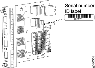
Serial number location |
The serial number label is yellow and located as shown in Figure 14. Figure 14: SRX-MIC-10XG-SFPP Serial
Number Label
 |
MIC with 1x100GE CFP Interface (SRX-MIC-1X100G-CFP)
You use MICs and MPCs to add different combinations of Ethernet interfaces to your firewall to suit the specific needs of your network. The SRX-MIC-1X100G-CFP (see Figure 15) can be installed in an MPC to add one 100-Gigabit Ethernet CFP port.
Description |
|
Software release |
Junos OS Release 12.1X46-D10 |
Cables and connectors |
One socket for a 100-Gigabit CFP transceiver. Supported CFP transceivers:
|
Supported slots |
Either slot in SRX5K-MPC |
Weight |
Approximately 1.6 lb (0.7 kg) |
LEDs |
OK/FAIL LED, one bicolor:
LINK LED, single color:
|
Serial number location |
The serial number label is yellow and located as shown in Figure 16. Figure 16: SRX-MIC-1X100G-CFP Serial
Number Label
 |
MIC with 2x40GE QSFP+ Interfaces (SRX-MIC-2X40G-QSFP)
You use MICs and MPCs to add different combinations of Ethernet interfaces to your firewall to suit the specific needs of your network. The SRX-MIC-2X40G-QSFP (see Figure 17) can be installed in an MPC to add two 40-Gigabit quad small form-factor pluggable (QSFP+) Ethernet ports.
Description |
|
Software release |
Junos OS Release 12.1X46-D10 |
Cables and connectors |
Sockets for two QSFP+ 40-Gigabit Ethernet fiber-optic transceivers. Supported QSFP+ transceiver: 40GBASE-SR4 (model number SRX-QSFP-40G-SR4) 40GBASE-LR4 (model number SRX-QSFP-40G-LR4) |
Supported slots |
Either slot in SRX5K-MPC |
Weight |
Approximately 1.6 lb (0.7 kg) |
LEDs |
OK/FAIL LED, one bicolor:
LINK LED, single color, one per QSFP+ port:
|
Serial number location |
The serial number label is yellow and typically located as shown in Figure 18. Figure 18: SRX-MIC-2X40G-QSFP Serial
Number Label
 |
SRX5K-MPC3-40G10G Specifications
The SRX5K-MPC3-40G10G (IOC3) is an interface card that provides 10 Gigabit Ethernet and 40 Gigabit Ethernet interfaces, with a Packet Forwarding Engine that provides a 240 Gbps line rate. This interface card is supported on SRX5400, SRX5600, and SRX5800 Firewalls. See Figure 19.
These cards do not support plug-in Modular Interface Cards (MICs).
All ports on the interface card have dual-color LEDs for reporting link status.
The interface card also supports hot-pluggable optical modules.
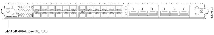
If a slot in the SRX5400, SRX5600, or SRX5800 Firewall card cage is not occupied by a card, you must install a blank panel to shield the empty slot and to allow cooling air to circulate properly through the firewall.
Description |
|
Software release |
Junos OS Release 15.1X49-D10 and later |
Supported Slots |
|
Cables and connectors |
Sockets for 40-Gbps and 10-Gbps SFP+ transceivers See Hardware Compatibility Tool for the transceivers supported. |
Power requirements |
Typical: 9.68 A @ 48 V (460 W) At different temperatures:
|
Weight |
21 lb (9.52 kg) |
Hardware features |
|
Software features |
Note:
At any one time you can have only one of the following PIC combinations powered on:
If you configure any of the following invalid PIC combinations, the chassis will set PIC0 & PIC1 combination online.
|
LEDs |
OK/FAIL LED, one bicolor:
10-Gigabit Ethernet LINK LED, one green per port:
40-Gigabit Ethernet LINK LED, one bicolor per port:
|
Serial Number Location |
The serial number label is located as shown in Figure 20. Figure 20: SRX5K-MPC3-40G10G Serial Number Label
 |
SRX5K-MPC3-100G10G Specifications
The SRX5K-MPC3-100G10G (IOC3) is an interface card that provides 100 Gigabit Ethernet and 10 Gigabit Ethernet interfaces, with a Packet Forwarding Engine that provides a 240 Gbps line rate. This interface card is supported on SRX5400, SRX5600, and SRX5800 Firewalls. See Figure 21.
These cards do not support plug-in Modular Interface Cards (MICs).
All ports on the interface card have dual-color LEDs for reporting link status.
The interface card also supports hot-pluggable optical modules.
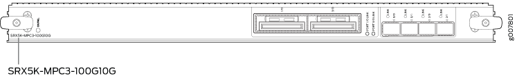
If a slot in the SRX5400, SRX5600, or SRX5800 Firewall card cage is not occupied by a card, you must install a blank panel to shield the empty slot and to allow cooling air to circulate properly through the firewall.
Description |
|
Software release |
Junos OS Release 15.1X49-D10 and later |
Supported Slots |
|
Cables and connectors |
Sockets for 100-Gbps and 10-Gbps SFP+ transceivers See Hardware Compatibility Tool for the transceivers supported. |
Power requirements |
At different temperatures:
|
Weight |
21 lb (9.52 kg) |
Hardware features |
The ports are labeled as:
|
Software features |
|
LEDs |
OK/FAIL LED, one bicolor:
10-Gigabit Ethernet LINK LED, one bicolor per port:
100-Gigabit Ethernet LINK LED, one bicolor per port:
|
Serial Number Location |
The serial number label is located as shown in Figure 22. Figure 22: SRX5K-MPC3-100G10G Serial Number Label
 |
SRX5K-IOC4-10G Specifications
SRX5K-IOC4-10G is a fixed-configuration interface card with a Packet Forwarding Engine that provides 400-Gbps line rate. This interface card provides scalability in bandwidth and services to the SRX5400, SRX5600 and SRX5800 Firewalls. See Figure 23.
SRX5K-IOC4-10G cards do not support plug-in Modular Interface Cards (MICs).
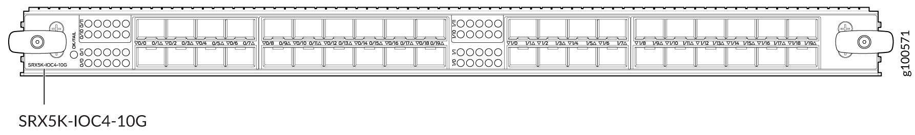
If a slot in the SRX5400, SRX5600, or SRX5800 Firewall card cage is not occupied by a card, you must install a blank panel to shield the empty slot and to allow cooling air to circulate properly through the firewall.
Description |
|
Software release |
Junos OS Release 19.3R1 and later |
Supported slots |
|
Cables and connectors |
See Hardware Compatibility Tool for the transceivers supported. |
Power requirements |
At different temperatures:
|
Weight |
17 lb (7.7 kg) |
Hardware features |
|
Software features |
|
LEDs |
OK/FAIL LED, one bicolor:
LINK LED, one green per port:
|
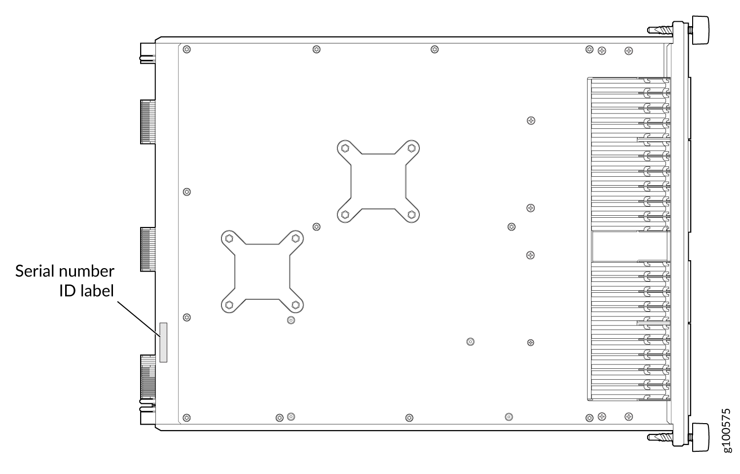
Serial Number Location |
The serial number label is located as shown in Figure 24. Figure 24: SRX5K-IOC4-10G Serial
Number Label
 |
SRX5K-IOC4-MRAT Specifications
SRX5K-IOC4-MRAT is a fixed-configuration interface card with a Packet Forwarding Engine that provides up to 480-Gbps (240-Gbps per PIC slot) line rate. This interface card provides scalability in bandwidth and services to the SRX5400, SRX5600, and SRX5800 Firewalls. See Figure 25.
SRX5K-IOC4-MRAT cards do not support plug-in Modular Interface Cards (MICs).
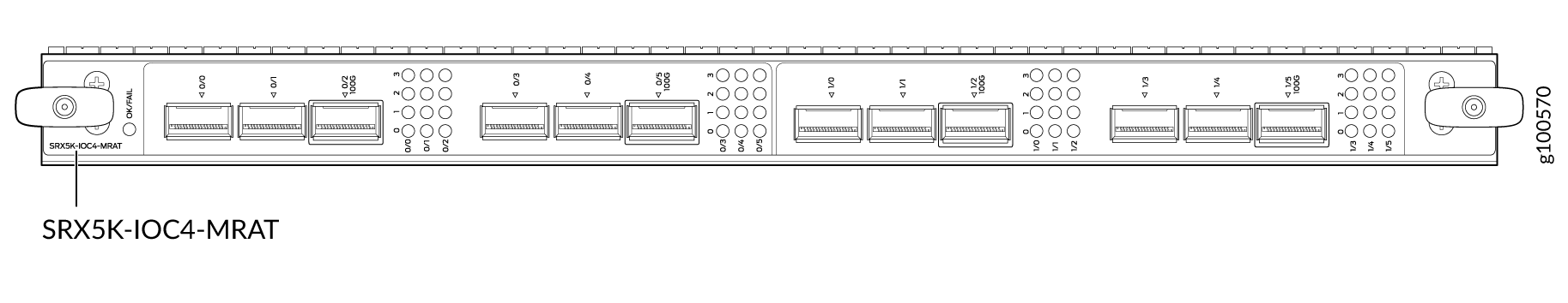
If a slot in the SRX5400, SRX5600, or SRX5800 Firewall card cage is not occupied by a card, you must install a blank panel to shield the empty slot and to allow cooling air to circulate properly through the firewall.
Description |
|
Software release |
Junos OS Release 19.3R1 and later |
Supported Slots |
|
Cables and connectors |
See Hardware Compatibility Tool for the transceivers supported. |
Power requirements |
At different temperatures:
|
Weight |
15.7 lb (7.12 kg) |
Hardware features |
|
Software features |
|
LEDs |
OK/FAIL LED, one bicolor:
LINK LED, one green per port (4 per QSFP+ cage):
|
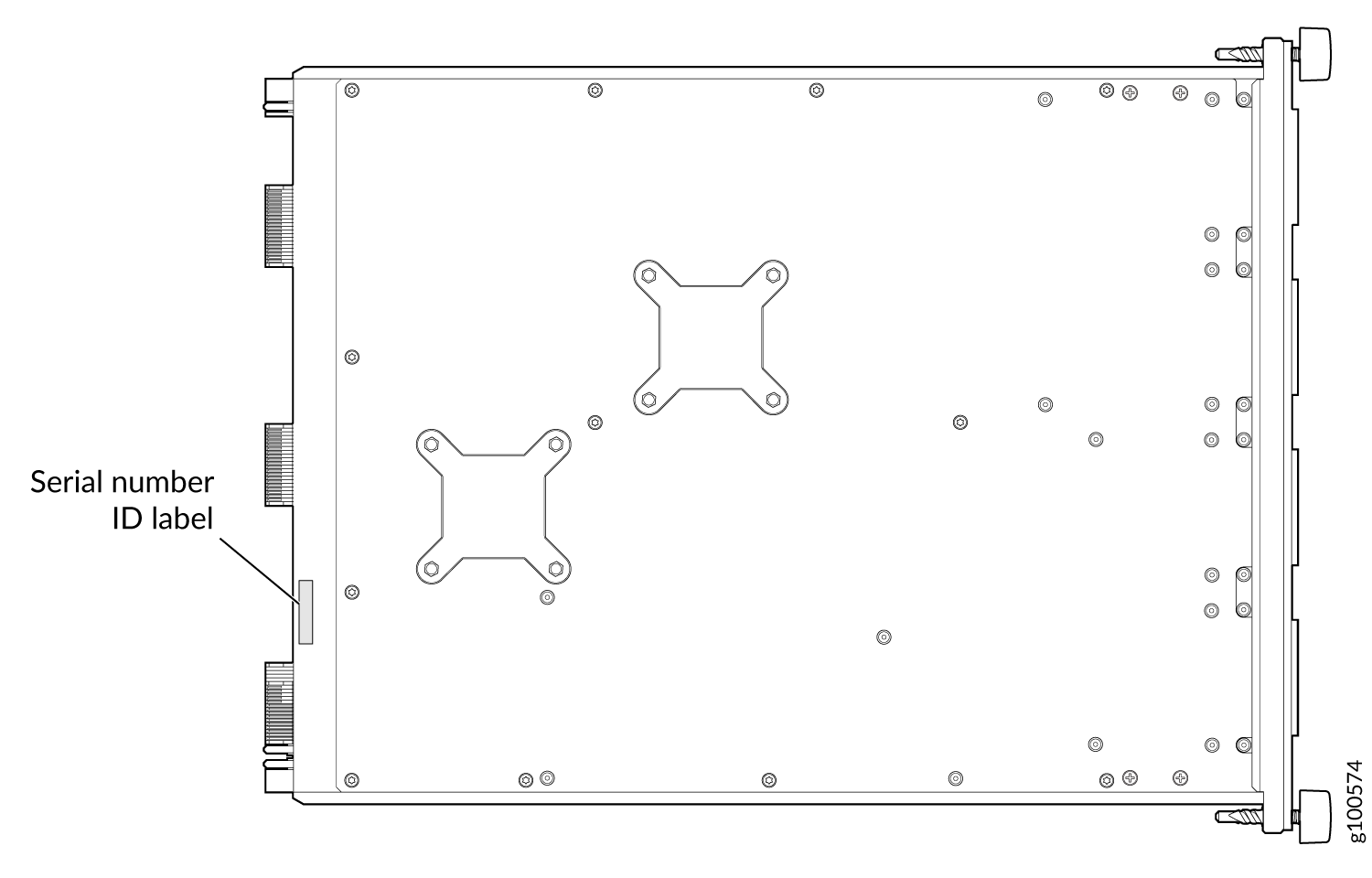
Serial Number Location |
The serial number label is located as shown in Figure 26. Figure 26: SRX5K-IOC4-MRAT
Serial Number Label
 |
SRX5800 Firewall Interface Card Description
Interface cards are cards that support physical interfaces that you use to connect the firewall to your data network. Three different types of interface cards are available:
I/O Cards (IOCs) have fixed interface ports on the front panel of the card.
Flex I/O Cards (Flex IOCs) have slots on the front panel that accept smaller cards called port modules. Each port module has two or more physical interfaces on it. A Flex IOC with installed port modules functions in the same way as a regular IOC, but allows greater flexibility in adding different types of Ethernet ports to your firewall.
Modular Port Concentrators (MPCs) have slots on the front panel that accept smaller cards called Modular Interface Cards (MICs). Each MIC has one or more physical interface on it. An MPC with MICs installed functions in the same way as a regular I/O card (IOC), but allows greater flexibility in adding different types of Ethernet ports to your firewall. MPCs and MICs are similar in form and function to Flex IOCs and port modules. However, the two use different form-factors, so you cannot install port modules in an MPC, nor can you install MICs in a Flex IOC.
For all interface card types, the card assembly combines packet forwarding and Ethernet interfaces on a single board. The interface cards interface with the power supplies and Switch Control Boards (SCBs).
You can install interface cards in any of the slots that are not reserved for SCBs. If a slot is not occupied by a card, you must install a blank panel to shield the empty slot and to allow cooling air to circulate properly through the firewall.
Figure 27 shows typical IOCs supported on the firewall.
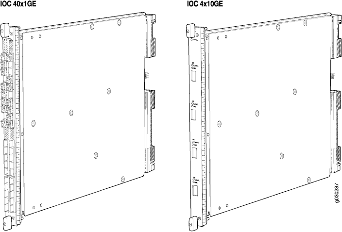
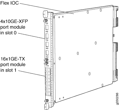
Figure 28 shows a Flex IOC with two typical port modules installed.

Figure 29 shows an MPC.

For detailed information about the interface cards, port modules, and MICs supported by the firewall, see the SRX5400, SRX5600, and SRX5800 Firewall Card Reference at www.juniper.net/documentation/.
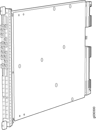
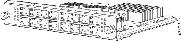
I/O Card SRX5K-40GE-SFP Specifications
The SRX5K-40GE-SFP I/O card (IOC) is optimized for Ethernet density and supports 40 Gigabit Ethernet ports (see Figure 30). The IOC assembly combines packet forwarding and Ethernet interfaces on a single board, with four 10-Gbps Packet Forwarding Engines. Each Packet Forwarding Engine consists of one I-chip for Layer 3 processing and one Layer 2 network processor. The IOCs interface with the power supplies and Switch Control Boards (SCBs).
You must install at least one IOC in the firewall. The IOC can be of any of the available IOC or Flex IOC types.
You can install IOCs in any of the slots that are not reserved for Switch Control Boards (SCBs). If a slot is not occupied by a card, you must install a blank panel to shield the empty slot and to allow cooling air to circulate properly through the firewall.
Description |
|
Software release |
|
Cables and connectors |
40 Gigabit Ethernet SFP ports Supported SFP transceivers: 1000BASE-LH (model numbers SRX-SFP-1GE-LH, SRX-SFP-1GE-LH-ET) 1000BASE-LX (model numbers SRX-SFP-1GE-LX, SRX-SFP-1GE-LX-ET) 1000BASE-SX (model numbers SRX-SFP-1GE-SX, SRX-SFP-1GE-SX-ET) 1000BASE-T (model numbers SRX-SFP-1GE-T, SRX-SFP-1GE-T-ET) |
Controls |
None |
Supported Slots |
|
Power Requirement |
312 W typical, 365 W maximum |
Weight |
Approximately 13 lb (5.9 kg) |
LEDs |
OK/FAIL LED, one bicolor:
|
Serial Number Location |
The serial number label is located as shown in Figure 31. Figure 31: Serial Number Label (IOC Shown,
Other Cards Similar)
|
I/O Card SRX5K-4XGE-XFP Specifications
The SRX5K-4XGE-XFP I/O card (IOC) supports four 10-Gigabit Ethernet ports (see Figure 32). The IOC assembly combines packet forwarding and Ethernet interfaces on a single board, with four 10-Gbps Packet Forwarding Engines. Each Packet Forwarding Engine consists of one I-chip for Layer 3 processing and one Layer 2 network processor. The IOCs interface with the power supplies and Switch Control Boards (SCBs).
You must install at least one IOC in the firewall. The IOC can be of any of the available IOC or Flex IOC types.
You can install IOCs in any of the slots that are not reserved for Switch Control Boards (SCBs). If a slot is not occupied by a card, you must install a blank panel to shield the empty slot and to allow cooling air to circulate properly through the firewall.
Description |
|
Software release |
|
Cables and connectors |
Four 10-Gbps XFP ports Supported XFP transceivers: 10GBASE-ER (model numbers SRX-XFP-10GE-ER and SRX-XFP-10GE-ER-ET ) 10GBASE-LR (model numbers SRX-XFP-10GE-LR and SRX-XFP-10GE-LR-ET 10GBASE-SR (model numbers SRX-XFP-10GE-SR and SRX-XFP-10GE-SR-ET ) |
Controls |
None |
Supported Slots |
|
Power Requirement |
312 W typical, 365 W maximum |
Weight |
Approximately 13 lb (5.9 kg) |
LEDs |
OK/FAIL LED, one bicolor:
|
Serial Number Location |
The serial number label is located as shown in Figure 33. Figure 33: SRX5K-4XGE-XFP Serial Number Label
|
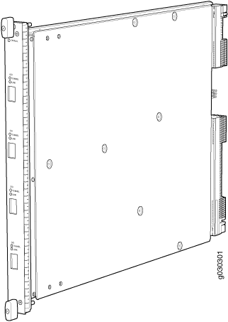
Flex I/O Card (SRX5K-FPC-IOC) Specifications
The SRX5K-FPC-IOC Flex I/O card (Flex IOC) (Figure 34) is an IOC with two slots that accept port modules that add Ethernet ports to your firewall. A Flex IOC with installed port modules functions in the same way as a regular IOC, but allows greater flexibility in adding different types of Ethernet ports to your firewall.
Each Flex IOC has a processor subsystem, which includes a 1.2-GHz CPU, a system controller, 1 GB SDRAM, and two Packet Forwarding Engines with a maximum throughput of 10 Gbps each.
You must install at least one IOC in the firewall. The IOC can be of any of the available IOC or Flex IOC types.
You can install Flex IOCs in any of the slots that are not reserved for Switch Control Boards (SCBs). If a slot is not occupied by a card, you must install a blank panel to shield the empty slot and to allow cooling air to circulate properly through the firewall.
Description |
|
Software release |
|
Cables and connectors |
Slots for two port modules |
Controls |
None |
Supported Slots |
|
Power Requirement |
312 W typical, 365 W maximum (includes port modules) |
Weight |
Approximately 10 lb (4.5 kg) |
LEDs |
OK/FAIL LED, one bicolor:
|
Serial Number Location |
The serial number label is located as shown in Figure 35. Figure 35: Serial Number Label (IOC Shown,
Other Cards Similar)
|
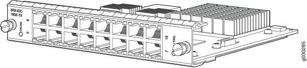
Flex I/O Card Port Module SRX-IOC-16GE-SFP Specifications
You use port modules and Flex I/O Cards (Flex IOCs) to add different combinations of small form-factor pluggable transceiver (SFP), 10-gigabit SFP transceiver (XFP), and copper ports to your firewall to suit the specific needs of your network. The SRX-IOC-16GE-SFP port module (Figure 36) installs into a Flex IOC to add sixteen 10/100/1000 Ethernet SFP ports.
Description |
|
Software release |
|
Cables and connectors |
16 Gigabit Ethernet SFP ports Supported SFP transceivers: 1000BASE-LH (model numbers SRX-SFP-1GE-LH, SRX-SFP-1GE-LH-ET) 1000BASE-LX (model numbers SRX-SFP-1GE-LX, SRX-SFP-1GE-LX-ET) 1000BASE-SX (model numbers SRX-SFP-1GE-SX, SRX-SFP-1GE-SX-ET) 1000BASE-T (model numbers SRX-SFP-1GE-T, SRX-SFP-1GE-T-ET) |
Controls |
ONLINE Button–The ONLINE button on the port module front panel toggles the port module online and offline |
Supported Slots |
Either slot in SRX5K-FPC-IOC Flex IOC |
Weight |
Approximately 1.6 lb (0.7 kg) |
LEDs |
OK/FAIL LED, one bicolor:
LINK LED, single color, one per port:
TX/RX LED, single color, one per port:
|
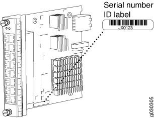
Serial Number Location |
The serial number label is located as shown in Figure 37. Figure 37: Port Module SRX-IOC-16GE-SFP
Serial Number Label
 |
Flex I/O Card Port Module SRX-IOC-16GE-TX Specifications
You use port modules and Flex I/O Cards (Flex IOCs) to add different combinations of small form-factor pluggable transceiver (SFP), 10-gigabit SFP transceiver (XFP), and copper ports to your firewall to suit the specific needs of your network. The SRX-IOC-16GE-TX port module (Figure 38) installs into a Flex IOC to add sixteen 10/100/1000 Ethernet RJ-45 copper ports.
Description |
|
Software release |
|
Cables and connectors |
Sixteen RJ-45 1-Gbps ports |
Controls |
ONLINE Button–The ONLINE button on the port module front panel toggles the port module online and offline. |
Supported Slots |
Either slot in SRX5K-FPC-IOC Flex IOC |
Weight |
Approximately 1.6 lb (0.7 kg) |
LEDs |
OK/FAIL LED, one bicolor:
LINK LED, single color, one per port:
TX/RX LED, single color, one per port:
|
Serial Number Location |
The serial number label is located as shown in Figure 39. Figure 39: Port Module SRX-IOC-16GE-TX
Serial Number Label
 |
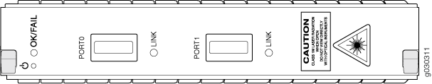
Flex I/O Card Port Module SRX-IOC-4XGE-XFP Specifications
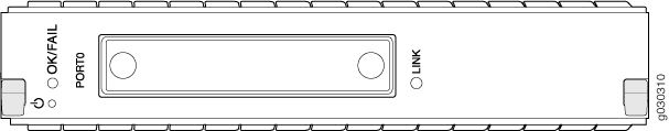
You use port modules and Flex I/O Cards (Flex IOCs) to add different combinations of small form-factor pluggable transceiver (SFP), 10-gigabit SFP transceiver (XFP), and copper ports to your firewall to suit the specific needs of your network. The SRX-IOC-4XGE-XFP port module (Figure 40) installs into a Flex IOC to add four 10-Gigabit Ethernet XFP ports.
Description |
|
Software release |
|
Cables and connectors |
4 XFP Ethernet ports Supported XFP transceivers: 10GBASE-ER (model numbers SRX-XFP-10GE-ER and SRX-XFP-10GE-ER-ET ) 10GBASE-LR (model numbers SRX-XFP-10GE-LR and SRX-XFP-10GE-LR-ET 10GBASE-SR (model numbers SRX-XFP-10GE-SR and SRX-XFP-10GE-SR-ET ) |
Controls |
ONLINE Button–The ONLINE button on the port module front panel toggles the port module online and offline |
Supported Slots |
Either slot in SRX5K-FPC-IOC Flex IOC |
Weight |
Approximately 1.6 lb (0.7 kg) |
LEDs |
OK/FAIL LED, one bicolor:
LINK LED, single color, one per port:
|
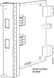
Serial Number Location |
The serial number label is located as shown in Figure 41. Figure 41: Port Module SRX-IOC-4XGE-XFP
Serial Number Label
 |