ON THIS PAGE
SRX5800 Host Subsystem
SRX5800 Firewall Host Subsystem Description
The host subsystem is composed of a Routing Engine installed in a Switch Control Board (SCB). The host subsystem provides the routing and system management functions of the firewall. You must install one host subsystem on the device. The host subsystem components are as follows:
Switch Control Board
SRX5K-SCB–from Junos OS Release 9.2 to 12.3X48
SRX5K-SCBE–from Junos OS Release 12.1X47-D15 and later
SRX5K-SCB3–from Junos OS Release 15.1X49-D10 and later
SRX5K-SCB4–from Junos OS Release 19.3R1 and later
Note:SRX5K-SCB4 is not supported on SRX5400 Firewalls.
Routing Engine
SRX5K-RE-13-20–from Junos OS Release 9.2 to 12.3X48
SRX5K-RE-1800X4–from Junos OS Release 12.1X47-D15 and later
SRX5K-RE3-128G–from Junos OS Release 19.3R1 and later
You can only configure the following combination of Routing Engine and SCB within a host subsystem:
SRX5K-RE-13-20 and SRX5K-SCB
SRX5K-RE-1800X4 and SRX5K-SCBE
SRX5K-RE-1800X4 and SRX5K-SCB3
SRX5K-RE-1800X4 and SRX5K-SCB4
SRX5K-RE3-128G and SRX5K-SCB3 or SRX5K-SCB4
The host subsystem has three LEDs that display its status. The host subsystem LEDs are located in the middle of the craft interface.
Switch Control Board SRX5K-SCB Overview
The Switch Control Board (SCB) provides the following functions:
Powers on and powers off IOCs and SPCs
Controls clocking, system resets, and booting
Monitors and controls system functions, including fan speed, board power status, PDM status and control, and the system front panel
Provides interconnections to all the IOCs within the chassis through the switch fabrics integrated into the SCB
When the SCB is part of a host subsystem, the Routing Engine installs directly into a slot on the SCB (see Figure 1).
The SRX5800 Firewall has two SCBs installed and you can install a third SCB for switch fabric redundancy.
The SRX5800 Firewall supports a redundant SCB, provided the SCB is a SRX5K-SCBE (SCB2) running Junos OS Release 12.1X47-D15 and later, SRX5K-SCB3 (SCB3) running Junos OS Release 15.1X49-D10 and later, or a SRX5K-SCB4 (SCB4) running Junos OS Release 19.3R1 and later.The SRX5800 Firewall does not support a redundant SCB (third SCB) card if SRX5K-SPC-4-15-320 (SPC2) is installed with SCB1 (SRX5K-SCB). If you have installed a SPC2 on a SRX5800 Firewall with a redundant SCB1 card, make sure to remove the redundant SCB1 card.
SCBs install vertically into the front of the chassis. The SCB slots are located at the middle of the card cage and are labeled 0, 1, and 2/6. If any slots are empty, you must install a blank panel.
SCBs installed in slots 0 and 1 provide nonredundant fabric connections. A SCB installed in slot 2/6, in conjunction with SCBs in slots 0 and 1, provides redundant fabrics. If no SCB is installed in slot 2/6, you must install a blank panel in the slot (see Table 1).
Functionality |
Slot 0 |
Slot 1 |
Slot 2/6 |
|---|---|---|---|
Full fabric |
SCB Routing Engine |
SCB |
– |
Redundant fabric |
SCB Routing Engine |
SCB |
SCB |
For detailed information about SCBs supported by the SR5800 Firewall, see the SRX5400, SRX5600, and SRX5800 Firewall Card Guide at www.juniper.net/documentation/.
Switch Control Board SRX5K-SCB Specifications
The SRX5K-SCB Switch Control Board (SCB) (Figure 2) performs the following functions:
Powers on and powers off I/O cards (IOCs) and Services Processing Cards (SPCs)
Controls clocking, system resets, and booting
Monitors and controls system functions, including fan speed, board power status, PDM status and control, and the system front panel
Provides interconnections to all the IOCs within the chassis through the switch fabrics integrated into the SCB
SRX5400 and SRX5600 Firewalls have one SCB each installed and you can install a second SCB for redundancy. The SRX5800 Firewall has two SCBs installed and you can install a third SCB for switch fabric redundancy.
The host subsystem is composed of a Routing Engine installed directly into a slot on the faceplate of the SCB. When there is no Routing Engine is a SCB, its slot must be covered with a blank panel.

Each SCB consists of the following components:
Chassis management Ethernet switch.
I2C bus logic, used for low-level communication with each component.
Component redundancy circuitry.
Gigabit Ethernet switch that is connected to the embedded CPU complex on all components.
Switch fabric—Provides the switching functions for the IOCs.
Control FPGA—Provides the Peripheral Component Interconnect (PCI) interface to the Routing Engine.
1000Base-T Ethernet controller—Provides a 1-Gbps Ethernet link between the Routing Engines.
Ethernet switch—Provides 1-Gbps link speeds between the Routing Engine and the IOCs.
Circuits for chassis management and control.
Power circuits for the Routing Engine and SCB.
Description |
|
Software release |
|
Cables and connectors |
Slot for Routing Engine |
Controls |
None |
Supported Slots |
|
Power Requirement |
150 W |
Weight |
Approximately 10 lb (4.5 kg) |
LEDs |
OK/FAIL LED, one bicolor:
FABRIC ONLY LED:
FABRIC ACTIVE LED:
|
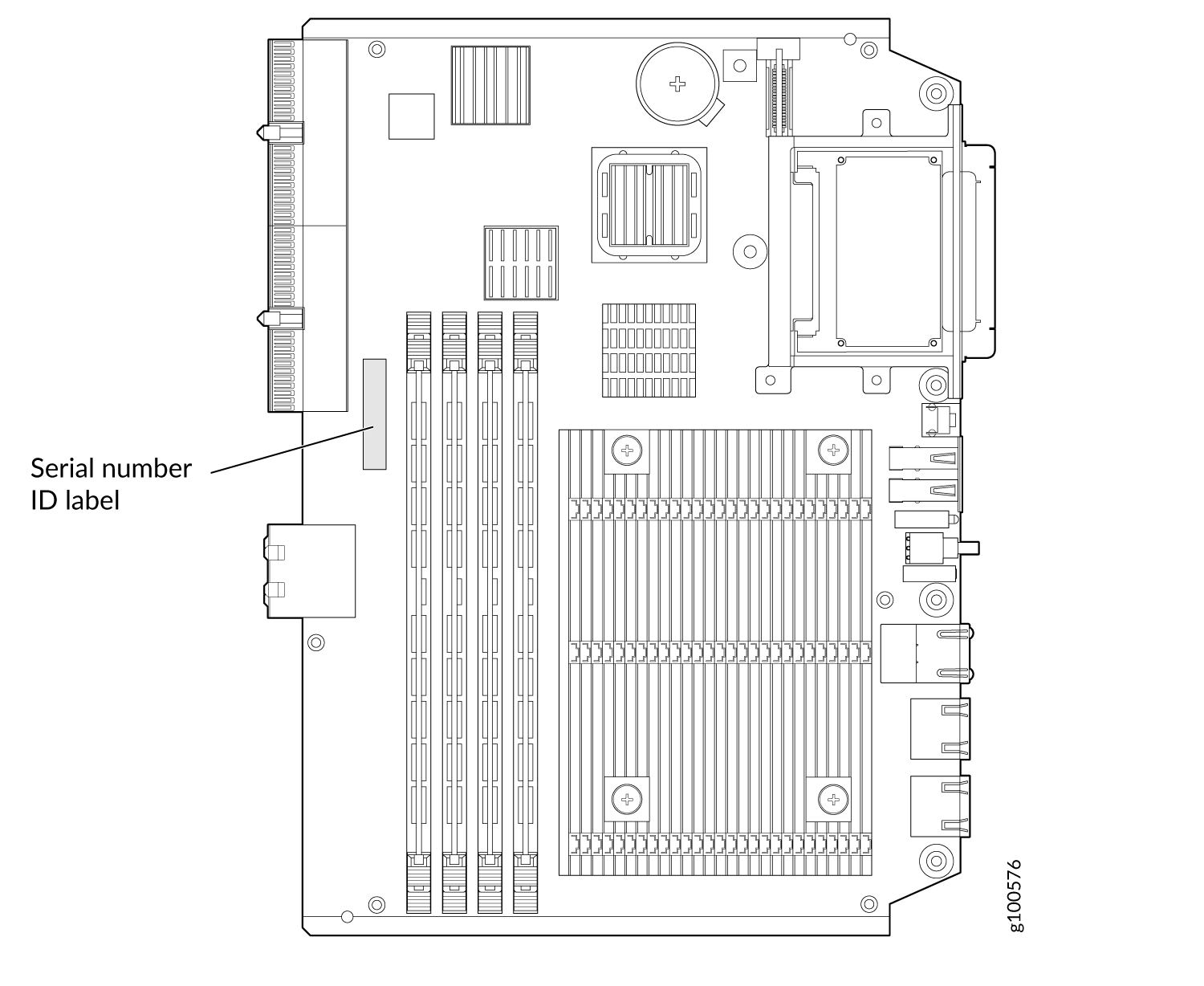
Serial Number Location |
The serial number label is located as shown in Figure 3. Figure 3: SCB Serial Number Label
 |
Switch Control Board SRX5K-SCBE Overview
The SRX5000 line enhanced Switch Control Board (SRX5K-SCBE) caters to high-end security markets requiring support for higher capacity traffic. The SRX5K-SCBE provides greater interface density (slot and capacity scale) and improved services.
Some key attributes of the SRX5K-SCBE are:
A bandwidth of 120 Gbps per slot with redundant fabric support and improved fabric performance by using the next-generation fabric (XF) chip.
A centralized clocking architecture that supports clock cleanup and distribution. The Stratum 3 clock module performs clock monitoring, filtering, and holdover in a centralized chassis location.
Full performance with fabric redundancy for higher capacity line cards such as the SRX5K-MPC.
The Routing Engine installs directly into a slot on the SRX5K-SCBE as shown in Figure 4.
Switch Control Board SRX5K-SCBE Specifications
Each SRX5K-SCBE consists of the following components:
I2C bus logic for low-level communication with each component
Component redundancy circuitry
Control Board/Routing Engine primary-role mechanism
Gigabit Ethernet switch that is connected to the embedded CPU complex on all components
Switch fabric to provide the switching functions for the MPCs
1000BASE-T Ethernet controller to provide a 1-Gbps Ethernet link between the Routing Engines
Power circuits for the Routing Engine and the SRX5K-SCBE
LEDs—Provides status of the SRX5K-SCBE and clocking interface
| Description |
|
| Software release | Junos OS Release 12.1X47-D15 and later |
| Cables and connectors | Slot for Routing Engine |
| Controls | None |
| Supported slots |
|
| Power requirement |
|
| Weight | 9.6 lb (4.4 kg) with Routing Engine |
| Serial number location | The serial number label is located as shown in Figure 5. Figure 5: SRX5K-SCBE Serial Number Label
|
SRX5K-SCBE LEDs
Table 2 describes the SRX5K-SCBE LEDs and their states.
| Label | Color | State | Description |
|---|---|---|---|
FABRIC ACTIVE |
Green |
On steadily |
Fabric is in active mode. |
FABRIC ONLY |
Green |
On steadily |
SRX5K-SCBE operates in fabric-only mode. |
None |
Off |
SRX5K-SCBE operates in fabric/control board mode. |
|
OK/FAIL |
Green |
On steadily |
SRX5K-SCBE is online. |
Red |
On steadily |
SRX5K-SCBE has failed. |
|
None |
Off |
SRX5K-SCBE is offline. |
Switch Control Board SRX5K-SCB3 Overview
The SRX5K-SCB3 (SCB3) caters to high-end security markets requiring support for higher capacity traffic, greater interface density (slot and capacity scale), and improved services. The SCB3 is supported on SRX5400, SRX5600, and SRX5800 Firewalls.
The SCB3 supports the standard midplane and the enhanced midplane.
Some key attributes of the SCB3 are:
With the existing midplane and fabric link speed of 8.36 Gbps, supports a bandwidth of 205 Gbps per slot with redundant fabric support and 308 Gbps per slot without redundancy.
With the enhanced midplane and fabric link speed of 10.2 Gbps, supports a bandwidth of 249 Gbps per slot with redundant fabric support and 374 Gbps per slot without redundancy with the enhanced midplane
Improved fabric performance with the next-generation fabric (XF2) chip.
Full performance with fabric redundancy for higher-capacity line cards.
Support for MPC line cards such as SRX5K-MPC (IOC2), IOC3 (SRX5K-MPC3-40G10G or SRX5K-MPC3-100G10G), and IOC4 (SRX5K-IOC4-10G or SRX5K-IOC4-MRAT).
Two 10-Gigabit Ethernet SFP+ ports (These ports are disabled and reserved for future use).
The Routing Engine installs directly into a slot on the SCB3, as shown in Figure 6.
Switch Control Board SRX5K-SCB3 Specifications
Each SRX5K-SCB3 (SCB3) consists of the following components:
I2C bus logic for low-level communication with each component
Component redundancy circuitry
Control Board/Routing Engine primary-role mechanism
Gigabit Ethernet switch that is connected to the embedded CPU complex on all components
Switch fabric to provide the switching functions for the MPCs
Control field-programmable gate array (FPGA) to provide the Peripheral Component Interconnect (PCI) interface to the Routing Engine
Circuits for chassis management and control
Power circuits for the Routing Engine and SCB3
LEDs to provides status of the SCB3
| Description | SCB3 with slot for Routing Engine |
| Software release | Junos OS Release 15.1X49-D10 and later |
| Cables and connectors | Slot for Routing Engine |
| Controls | None |
| Supported slots |
|
| Power requirement | 300 W |
| Weight | 9.6 lb (4.4 kg) with Routing Engine |
| Serial number location | The serial number label is located as shown in Figure 7. Figure 7: SRX5K-SCB3 Serial Number Label
 |
SRX5K-SCB3 LEDs
Table 3 describes the SCB3 LEDs and their states.
Label |
Color |
State |
Description |
|---|---|---|---|
FABRIC ACTIVE |
Green |
On steadily |
Fabric is in active mode. |
OK/FAIL |
Green |
On steadily |
SCB3 is online. |
Red |
On steadily |
SCB3 has failed. |
|
– |
Off |
SCB3 is offline. |
|
LINK |
Green |
On steadily |
Port is enabled and link is established. |
– |
Off |
Port is disabled or no link is established. |
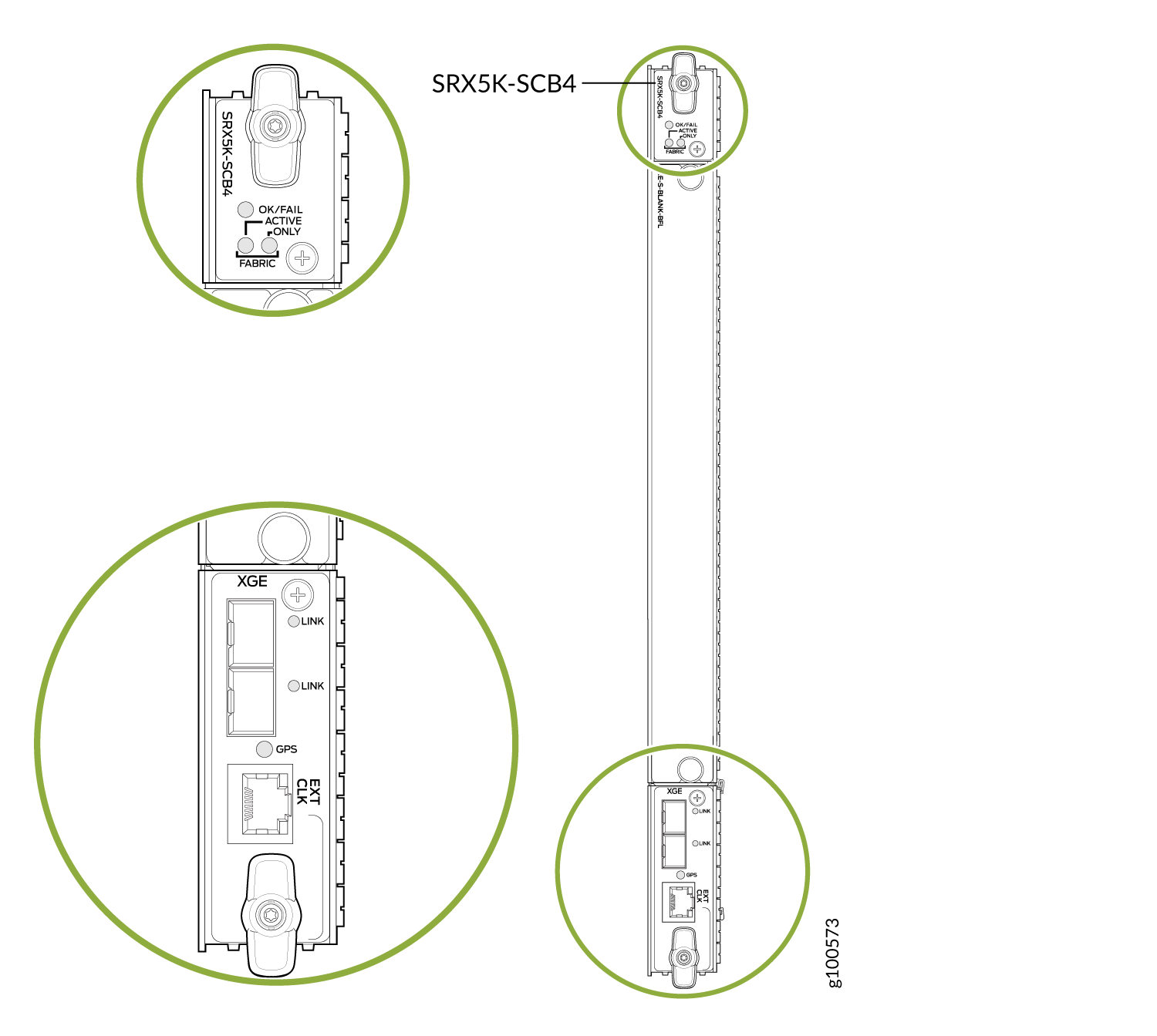
Switch Control Board SRX5K-SCB4 Overview
The SRX5K-SCB4 (SCB4) Enhanced Switch Control Board provides improved fabric performance and bandwidth capabilities for high-capacity line cards using the ZF-based switch fabric. The SCB4 is supported on SRX5600 and SRX5800 Firewalls, but not supported on SRX5400 Firewalls.
The SCB4 supports the standard and the enhanced midplane.
Some key attributes of the SCB4 are:
With the SRX5K-SCB4 Switch Control Board, Increased Fabric Bandwidth mode is the default mode on the SRX5600 and SRX5800 Firewalls and the firewalls will use six active planes without any spare planes.
With the Redundant Fabric mode, the SRX5600 and SRX5800 Firewalls will use four active planes and will have two spare planes.
-
SRX5K-SCB4, with fabric link speed of 19 Gbps enables:
-
480 Gbps throughput per slot with enhanced midplane and fabric redundancy
-
720 Gbps throughput per slot with enhanced midplane and without fabric redundancy
-
Two 10-Gigabit Ethernet SFP+ ports (These ports are disabled and reserved for future use).
Increased Fabric Bandwidth mode is the default fabric mode of SCB4. In this mode you must install two SCB4s in SRX5600 and three SCB4s in SRX5800 Firewalls/Chassis clusters.
You can change the fabric mode of SCB4 from Increased Fabric Bandwidth mode to Redundant Fabric mode using the CLI. If you change the fabric mode of SCB4 to Redundant Fabric mode you must install two SCB4s in SRX5600 and you can install either two or three SCB4s in SRX5800 Firewalls.
If you are upgrading from SCB3 (Redundant Fabric mode is the default fabric mode in SCB2 and SCB3) to SCB4 and installing only two SCB4s, you must have Junos OS 19.3R1 or later and change the default fabric mode of SCB4s to Redundant Fabric mode by using the CLI.
To achieve maximum throughput on an SRX5800 Firewall, you must configure the firewall with 3x IOC4 + 7x SPC3 + 2x RE3 and only 2x SCB4s (configured in redundant fabric mode). This configuration makes your firewall fullyloaded with still two empty slots in the chassis. You must not install additional line cards or a third SCB in the empty slots. If you install a third SCB or an additional line card, the chassis will hit chassis power limit and one of the line cards will go offline due to power shortage.
You can change the fabric mode by following one of these two methods:
Use the CLI command
request chassis fabric mode <increased-bandwidth|redundant-fabric>Save the change in the Configuration file
set chassis fabric redundancy-mode increased-bandwidth
set chassis fabric redundancy-mode redundant
The Routing Engine installs directly into a slot on the SCB4, as shown in Figure 8.
Switch Control Board SRX5K-SCB4 Specifications
SRX5K-SCB4 (SCB4) consists of the following components:
LEDs to provides status of the SCB4.
Circuits for chassis management and control.
Power circuits for the Routing Engine and SCB4.
| Description | SCB4 with slot for SRX5K-RE-1800X4 and SRX5K-RE3-128G Routing Engines |
| Software release | Junos OS Release 19.3R1 and later |
| Cables and connectors | Slot for Routing Engine |
| Controls | None |
| Supported slots |
|
| Power requirement | At different temperatures:
|
| Cooling requirement | For efficient and reliable power and cooling, you must install SRX Series high-capacity power supplies and fan trays in the SRX Series chassis. |
| Weight and Dimensions |
|
| Serial number location | The serial number label is located as shown in Figure 9. Figure 9: SRX5K-SCB4 Serial Number Label
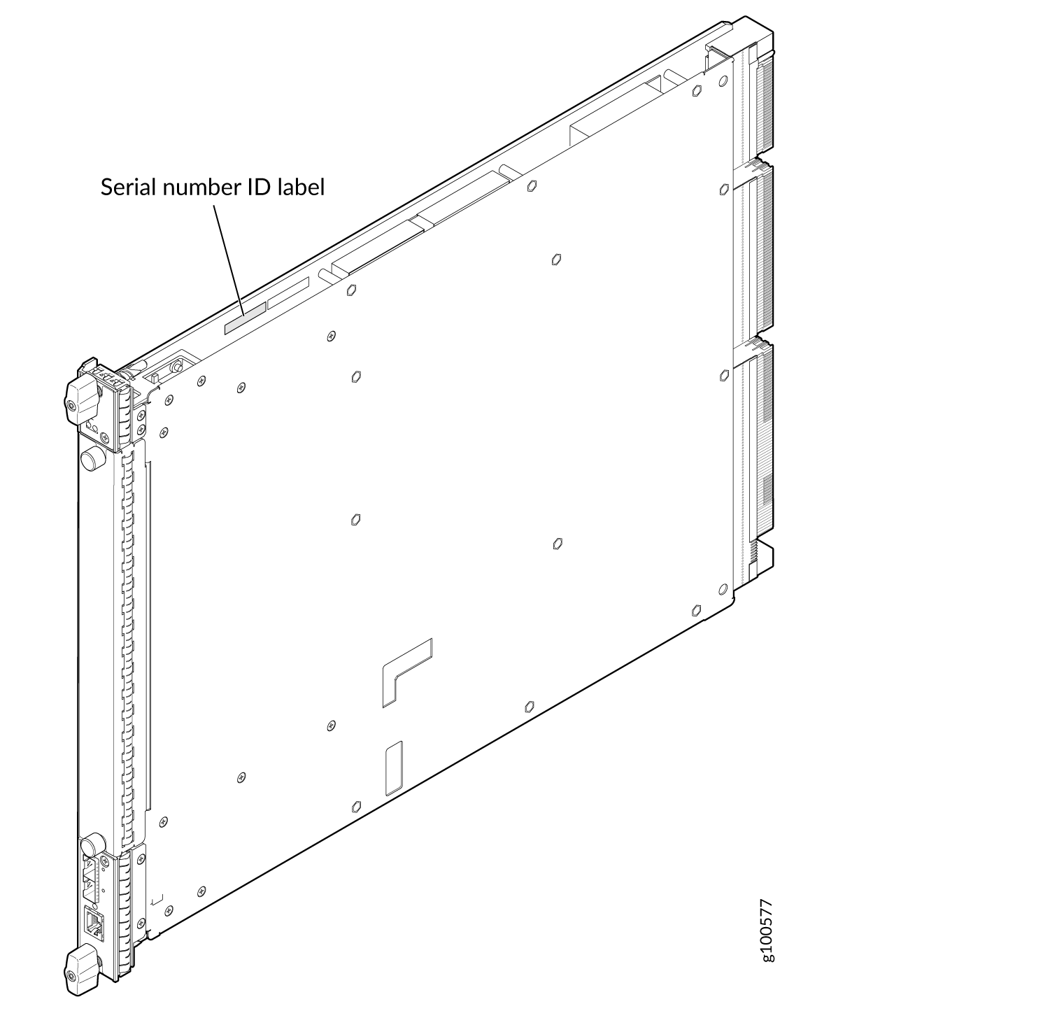 |
SRX5K-SCB4 LEDs
Table 4 describes the SCB4 LEDs and their states.
Label |
Color |
State |
Description |
|---|---|---|---|
OK/FAIL |
Green |
On steadily |
SCB4 is online. |
Red |
On steadily |
SCB4 has failed. |
|
– |
Off |
SCB4 is offline. |
|
FABRIC |
|||
ACTIVE |
Green |
On steadily |
The switch fabric on this board is in Active mode. |
ONLY |
Green |
On steadily |
The switch is in Fabric-Only mode. |
LINK (XGE port) |
Green |
On steadily |
SFP+ port is enabled and link is established. |
– |
Off |
SFP+ port is disabled or no link is established. |
|
GPS |
Green |
On steadily |
Indicates the status of the GPS clocking interface, and the link is OK. |
Yellow |
Blinking |
Activity on the clocking interface. |
|
Routing Engine SRX5K-RE-13-20 Overview
The Routing Engine is an Intel-based PC platform that runs Junos OS. Software processes that run on the Routing Engine maintain the routing tables, manage the routing protocols used on the device, control the device interfaces, control some chassis components, and provide the interface for system management and user access to the device.
You must install at least one Routing Engine in the firewall. You can install a second Routing Engine if both Routing Engines are running Junos OS Release 10.0 or later.
A second Routing Engine is required if you are using the dual chassis cluster control link feature available in Junos OS Release 10.0 and later. The second Routing Engine does not perform all the functions of a Routing Engine and does not improve resiliency or redundancy. The second Routing Engine and the Switch Control Board (SCB) in which it is installed do not constitute a host subsystem. The only function of the second Routing Engine is to enable the hardware infrastructure that enables the Chassis Cluster Control 1 port on the Services Processing Card (SPC) used for chassis cluster control links.
If you install only one Routing Engine in the firewall, you must install it in the slot in the front panel of SCB0. If you install a second Routing Engine to use the dual chassis cluster control link feature, you install it in the slot in the front panel of SCB1 (see Figure 10).
A USB port on the Routing Engine accepts a USB memory card that allows you to load Junos OS.
For detailed information about the Routing Engines supported by the firewall, see the SRX5400, SRX5600, and SRX5800 Firewall Card Reference at www.juniper.net/documentation/.
Routing Engine SRX5K-RE-13-20 Specifications
The SRX5K-RE-13-20 Routing Engine (Figure 11) is an Intel-based PC platform that runs the Junos operating system (Junos OS). Software processes that run on the Routing Engine maintain the routing tables, manage the routing protocols used on the device, control the device interfaces, control some chassis components, and provide the interface for system management and user access to the device.

You must install at least one Routing Engine in the firewall. You can install a second Routing Engine if both Routing Engines are running Junos OS Release 10.0 or later. A second Routing Engine is required if you are using the dual chassis cluster control link feature available in Junos OS Release 10.0 and later. The second Routing Engine does not perform all the functions of a Routing Engine and does not improve resiliency or redundancy. The second Routing Engine and the Switch Control Board (SCB) in which it is installed do not constitute a host subsystem. The only function of the second Routing Engine is to enable the hardware infrastructure that enables the chassis cluster control 1 port on the Services Processing Card (SPC) used for chassis cluster control links. If you install only one Routing Engine in the firewall, you must install it in the slot in the front panel of SCB0. If you install a second Routing Engine to use the dual chassis cluster control link feature, you install it in the slot in the front panel of SCB1.
The Routing Engine consists of the following components:
CPU—Runs Junos OS to maintain the firewall's routing tables and routing protocols. It has a Pentium-class processor.
DRAM—Provides storage for the routing and forwarding tables and for other Routing Engine processes.
USB port—Provides a removable media interface through which you can install Junos OS manually. Junos supports USB version 1.0.
Internal flash disk—Provides primary storage for software images, configuration files, and microcode. The disk is a fixed compact flash and is inaccessible from outside the firewall.
Hard disk—Provides secondary storage for log files, memory dumps, and rebooting the system if the internal compact flash disk fails.
HDD LED—Indicates disk activity for the hard disk drive.
Management ports—Each Routing Engine has one 10/100-Mbps Ethernet port for connecting to a management network, and two asynchronous serial ports—one for connecting to a console and one for connecting to a modem or other auxiliary device. The interface ports are labeled AUX, CONSOLE, and ETHERNET.
EEPROM—Stores the serial number of the Routing Engine.
Extractor clips—Used for inserting and extracting the Routing Engine.
Captive screws—Secures the Routing Engine in place.
The Routing Engine boots from the storage media in this order: the USB device (if present), then the internal flash disk, then the hard disk, then the LAN.
For specific information about Routing Engine components
(for example, the amount of DRAM), issue the show chassis routing-engine command.
Description |
Routing Engine for SRX5400, SRX5600, and SRX5800 Firewalls |
Software release |
|
Cables and connectors |
AUX—Connects the Routing Engine to a laptop, a modem, or another auxiliary device through a cable with an RJ-45 connector. CONSOLE—Connects the Routing Engine to a system console through a cable with an RJ-45 connector. ETHERNET—Connects the Routing Engine through an Ethernet connection to a management LAN (or any other device that plugs into an Ethernet connection) for out-of-band management. |
Controls |
|
Supported Slots |
Front panel slot in an SCB installed in:
Note:
The firewall host subsystem Routing Engine must be installed in the SCB in slot 0. A Routing Engine installed in an SCB in slot 1 only enables dual control links in chassis cluster configurations. |
Power Requirement |
90 W |
Weight |
Approximately 2.4 lb (1.1 kg) |
LEDs |
HDD LED:
MASTER LED:
Note:
The SRX5400, SRX5600, and SRX5800 Firewalls do not support a secondary or backup Routing Engine, so the MASTER LED should always be lit. OK/FAIL LED, one bicolor:
ONLINE LED:
|
Serial Number Location |
The serial number label is located on the right side of the top of the Routing Engine as shown in Figure 12 Figure 12: SRX5K-RE-13-20 Serial Number Label
 |
Routing Engine SRX5K-RE-1800X4 Overview
The enhanced Routing Engine is an Intel-based PC platform that runs Junos OS. Software processes that run on the Routing Engine maintain the routing tables, manage the routing protocols used on the device, control the device interfaces, control some chassis components, and provide the interface for system management and user access to the device.The Routing Engine must be installed directly into the SRX5K-SCBE. A USB port on the Routing Engine accepts a USB memory device that allows you to load Junos OS. Figure 13 shows the Routing Engine.
Three ports located on the Routing Engine connect to one or more external devices on which system administrators can issue Junos OS CLI commands to manage the firewall.
The ports function as follows:
AUX–Connects the Routing Engine to a laptop, modem, or other auxiliary device through a serial cable with an RJ-45 connector.
CONSOLE–Connects the Routing Engine to a system console through a serial cable with an RJ-45 connector.
ETHERNET–Connects the Routing Engine through an Ethernet connection to a management LAN (or any other device that plugs into an Ethernet connection) for out-of-band management. The port uses an autosensing RJ-45 connector to support 10/100/1000 Mbps connections. Two small LEDs on the bottom of the port indicate the connection in use: the LED flashes yellow or green for a 10/100/1000 Mbps connection, and the LED is light green when traffic is passing through the port.
The solid-state drive (SSD) slots located on the Routing Engine provide secondary storage for log files, for generating core files, and for rebooting the system if the CompactFlash card fails. Currently, SRX5K-RE-1800X4 only supports one 128-GB SSD.
SRX5K-RE-1800X4 Routing Engine Boot Sequence
The firewall is shipped with three copies of the Junos OS preinstalled on the Routing Engine in the following locations:
On the CompactFlash card in the Routing Engine
On the SSD in the Routing Engine
On a USB flash drive that can be inserted into the slot on the Routing Engine faceplate
Note:The hardware device packages shipped after September 2025 may not include bootable USB drives. If your device package does not include a bootable USB drive, we recommend that you create a bootable USB drive following the instructions provided in Best Practices for Upgrade/Downgrade from Bootable USB.
You may obtain a USB drive from any commercial source. The USB drive must have:
-
A minimum of 16 GB storage space
-
No security features, such as a keyed boot partition
-
The Routing Engine boots from the storage media in this order: the USB device (if present), the CompactFlash card, the solid-state drive (SSD), and then the LAN. Normally, the firewall boots from the copy of the software on the CompactFlash card.
Routing Engine SRX5K-RE-1800X4 Specifications
Each Routing Engine consists of the following components:
CPU—Runs Junos OS to maintain the routing tables and routing protocols.
DRAM—Provides storage for the routing and forwarding tables and for other Routing Engine processes.
USB port—Provides a removable media interface through which you can install the Junos OS manually. Junos OS supports USB version 1.0 and 2.0.
CompactFlash card—Provides primary storage for software images, configuration files, and microcode. The CompactFlash card is fixed and is inaccessible from outside the device.
Solid-state drive (SSD)—Provides secondary storage for log files, for generating core files, and for rebooting the system if the CompactFlash card fails.
Interface ports—The AUX, CONSOLE, and ETHERNET ports provide access to management devices. Each Routing Engine has one 10/100/1000-Mbps Ethernet port for connecting to a management network, and two asynchronous serial ports—one for connecting to a console and one for connecting to a modem or other auxiliary device.
EEPROM—Stores the serial number of the Routing Engine.
Reset button—Reboots the Routing Engine when pressed.
Online/Offline button—Takes the Routing Engine online or offline when pressed.
Extractor clips—Inserts and extracts the Routing Engine.
Captive screws—Secures the Routing Engine in place.
| Description | Routing Engine for SRX5400, SRX5600, and SRX5800 Firewalls |
| Software release | Junos OS Release 12.1X47-D15 and later |
| Cables and connectors | Slot for Routing Engine
|
| Controls | RESET button–Reboots the Routing Engine when pressed. |
| Supported slots | Front panel slot in an SCB installed in:
Note:
The firewall host subsystem Routing Engine must be installed in the SCB in slot 0. A Routing Engine installed in an SCB in slot 1 only enables dual control links in chassis cluster configurations. |
| Power requirement | 90 W |
| Weight | 2.4 lb (1.1 kg) |
| Serial number location | The serial number label is located as shown in Figure 14. Figure 14: SRX5K-RE-1800X4 Serial Number Label
 |
SRX5K-RE-1800X4 LEDs
Each Routing Engine has four LEDs that indicate its status. The LEDs, labeled MASTER, STORAGE, ONLINE, and OK/FAIL, are located directly on the faceplate of the Routing Engine. Table 5 describes the Routing Engine LEDs and their states.
| Label | Color | State | Description |
|---|---|---|---|
MASTER |
Blue |
On steadily |
Routing Engine is the primary. |
STORAGE |
Green |
Blinking |
Indicates activity on the SSD or CompactFlash card. |
ONLINE |
Green |
Blinking |
Routing Engine is transitioning online. |
None |
On steadily |
Routing Engine is functioning normally. |
|
OK/FAIL |
Red |
On steadily |
Routing Engine has failed. |
Routing Engine SRX5K-RE3-128G Specifications
The Routing Engine maintains the routing tables, manages the routing protocols used on the device, controls the device interfaces, controls some chassis components, and provides the interfaces for system management and user access to the device.
Figure 15 shows the SRX5K-RE3-128G Routing Engine.
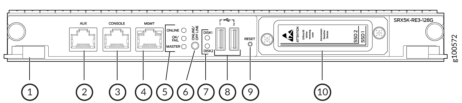
1 — Extractor clips | 6 — ONLINE/OFFLINE button |
2 — Auxiliary port (AUX) | 7 — SSD LEDs—DISK1 and DISK2 |
3 — Console port (CONSOLE) | 8 — USB ports—USB1 and USB2 |
4 — Management port (MGMT) | 9 — RESET button |
5 — Routing Engine status LEDs—ONLINE, OK/FAIL, and MASTER | 10 — SSD card slot cover |
| Description | Routing Engine for SRX5400, SRX5600, and SRX5800 Firewalls, based on Intel’s Haswell-EP CPU with 6 cores, and 128GB of DDR4 memory. It provides increased control plane performance and scalability along with virtualization features in the SRX Series 5000 line of chassis. |
| Software release | Junos OS Release 19.3R1 and later |
| Cables and connectors | Slot for Routing Engine
|
| Controls | RESET button–Reboots the Routing Engine when pressed. |
| Supported slots | Front panel slot in an SCB installed in:
Note:
The firewall host subsystem Routing Engine must be installed in the SCB in slot 0. A Routing Engine installed in an SCB in slot 1 only enables dual control links in chassis cluster configurations. Note:
In the SRX5600 or SRX5800 Firewalls chassis cluster configurations, dual control links functionality is not supported if you mix SRX5K-RE-1800X4 and SRX5K-RE3-128G Routing Engines. To support dual control links you have to install two SRX5K-RE3-128Gs. |
| Power requirement | 110 W |
| Weight | 2.69 lb (1.22 kg) |
| Serial number location | The serial number label is located as shown in Figure 16. Figure 16: SRX5K-RE3-128G Serial
Number Label
 |
- SRX5K-RE3-128G Routing Engine Components
- SRX5K-RE3-128G Routing Engine LEDs
- SRX5K-RE3-128G Routing Engine Boot Sequence
SRX5K-RE3-128G Routing Engine Components
Each Routing Engine consists of the following components:
CPU—Runs Junos OS to maintain the routing tables and routing protocols.
EEPROM—Stores the serial number of the Routing Engine.
DRAM—Provides storage for the routing and forwarding tables and for other Routing Engine processes.
One 10-Gigabit Ethernet interface between the Routing Engine and Switch Control Board.
Extractor clips—Control the locking system that secures the Routing Engine.
Interface ports—The AUX, CONSOLE, and MGMT ports provide access to management devices. Each Routing Engine has one 10/100/1000-Mbps Ethernet port for connecting to a management network, and two asynchronous serial ports—one for connecting to a console and one for connecting to a modem or other auxiliary device.
Note:The control interface names differ based on the routing engine:
For RE2, the control interfaces are displayed as
em0andem1.For RE3, the control interfaces are displayed as
ixlv0andigb0.
For more information, see show chassis cluster interfaces.
Status LEDs—Table 6 describes the functions of the ONLINE, OK/FAIL, MASTER, DISK1, and DISK2 LEDs.
ONLINE/OFFLINE button—Takes the Routing Engine online or offline when pressed.
Note:The ONLINE/OFFLINE button must be pressed for a minimum of 4 seconds.
USB1 and USB2 ports—Provide a removable media interface through which you can install Junos OS manually. Junos OS supports USB versions 3.0, 2.0, and 1.1.
RESET button—Reboots the Routing Engine when pressed.
SSD1 (primary) and SSD2 (secondary) Solid-state drives (SSD)—Two 200-GB each slim solid-state drives that provide storage for software images, configuration files, microcode, log files, and memory dumps. The Routing Engine reboots from SSD2 when boot from primary SSD1 fails.
Captive screws—Secures the Routing Engine.
SRX5K-RE3-128G Routing Engine LEDs
Each Routing Engine has four LEDs that indicate its status. The LEDs, labeled ONLINE, OK/FAIL, MASTER, DISK1, and DISK2, are located directly on the faceplate of the Routing Engine. Table 6 describes the Routing Engine LEDs and their states.
Label |
Color |
State |
Description |
|---|---|---|---|
ONLINE |
Green |
Blinking slowly |
Routing Engine is in the process of booting BIOS and the host OS. |
Blinking rapidly |
Routing Engine is in the process of booting Junos OS. |
||
- |
Off |
Routing Engine is not online or not functioning normally. |
|
OK/FAIL |
Green |
On steadily |
Routing Engine is powering up. |
Yellow |
On steadily |
Routing Engine is not powering up, which indicates failure. |
|
MASTER |
Blue |
On steadily |
This Routing Engine is the primary Routing Engine. |
DISK1 |
Green |
Blinking |
Indicates presence of disk activity. |
- |
Off |
There is no disk activity. |
|
DISK2 |
Green |
Blinking |
Indicates presence of disk activity. |
- |
Off |
There is no disk activity. |
SRX5K-RE3-128G Routing Engine Boot Sequence
Booting in a SRX5K-RE3-128G Routing Engine follows this sequence—the USB device, SSD1, SSD2, and LAN. SSD1 is the primary boot device. The boot sequence is tried twice for SSD1 and SSD2.