How to Install QFX5250 Liquid-cooled Switch (2OU) in ORv3 Rack
Use the information to install the ORv3-compliant QFX5250 liquid-cooled switiches in an ORv3 rack.
The liquid-cooled QFX5250 switches are ORv3-compliant. They can be directly installed on an ORv3 rack. The QFX5250 liquid-cooled model draws power from the rack.
English—Install this ORV3-compliant switch only on an Open Rack V3 compliant rack. Failure to comply may result in damage.
AVERTISSEMENT
French—Installez ce commutateur conforme à la norme ORV3 uniquement dans un bâti conforme à la norme Open Rack V3. Le non-respect de cette consigne peut entraîner des dommages matériels.
English—Installation and removal of this unit must be performed by qualified personnel (skilled persons) only. This equipment is intended for installation in a RESTRICTED ACCESS LOCATION only.
AVERTISSEMENT:
French—L'installation et le retrait de cette unité ne doivent être effectués que par du personnel qualifié (personnes compétentes). Cet équipement est conçu pour être installé uniquement dans un EMPLACEMENT À ACCÈS RESTREINT.
Unpack the ORv3-Compliant Switch
The chassis of QFX5250 switch is a rigid sheet-metal structure that houses the hardware components. We ship the switch in a cardboard carton, secured with foam packing material.
English—The switch has maximum protection inside the shipping carton. Do not unpack the switch until you are ready to begin installation.
AVERTISSEMENT
French—Le commutateur bénéficie d'une protection maximale à l'intérieur de son carton d'expédition. Ne déballez pas le commutateur avant d'être prêt à commencer l'installation.
To unpack the switch:
- Move the shipping carton to a staging area as close to the installation site as possible. Make sure that you have enough room to remove the system components.
- Position the carton so that the arrows are pointing up.
- Open the top flaps on the shipping carton.
- Remove the accessory box and verify the contents in it against the parts inventory on the label attached to the carton.
- Pull out the packing material holding the switch in place.
- Verify the chassis components received against the packing list included with the switch.
- Save the shipping carton and packing materials in case you need to move or ship the switch.
Parts Inventory (Packing List)
The shipment includes a packing list. Check the parts you receive in the shipping carton against the items on the packing list. We ship the parts as per the configuration that you order.
If any part on the packing list is missing, contact your customer service representative or contact Juniper customer care from within the U.S. or Canada by telephone at 1-888-314-5822. For international-dial or direct-dial options in countries without toll-free numbers, see https://www.juniper.net/support/requesting-support.html.
| Component | Model Number | Quantity |
|---|---|---|
|
Chassis |
QFX5250-64OE-L |
1 |
Juniper provides only the liquid-cooled switch. You are responsible for procuring and installing all other liquid-cooling components:
-
ORv3 rack
-
Liquid inlet and outlet manifolds
-
Hoses or tubing for the cooling system
-
Coolant distribution system (CDU) or centralized cooling system
-
Any other components for the cooling system
| Component | Quantity |
|---|---|
|
Documentation roadmap card |
1 |
| OSFP dust cover |
64 |
| SFP28 dust cover |
2 |
Ejector Lever Operation Guidelines
The QFX5250 liquid-cooled switch (QFX5250-64OE-L) is equipped with ejector levers on both the left and right side of the front panel. These levers must be operated in accordance with the recommended guidelines to ensure proper mechanical seating of the switch chassis and stable operation within the ORv3 rack. Incorrect or incomplete use of the ejector levers may result in the system becoming non-operational.
Ejector Lever Unlock Procedure
The recommended procedure for unlocking the ejector levers is as follows:
Press the release button on both ejector levers to disengage the locking mechanism.
Note: Ensure that both levers are fully opened.Once the levers are completely open, immediately slide the chassis fully out of the rack using the QFX5250 switch handles.
Note: Do not leave the chassis partially inserted with the ejector levers in a disengaged state.
Ejector Lever Lock Procedure
The recommended procedure for locking the ejector levers is as follows:
Insert the chassis fully into the rack using the QFX5250 switch handles.
Note: Ensure proper alignment and complete seating within the ORv3 rack while inserting the chassis.Engage both ejector levers uniformly to secure the chassis in place.
Note: Pauses or misalignment during switch insertion may result in transient power-related issues.
Key Considerations
-
Avoid partial insertion or uneven engagement of the ejector levers during the locking process.
-
Do not operate the system with ejector levers in a disengaged state.
For information on the steps to install the liquid-cooled QFX5250 switch in an ORv3 rack, see Install the Switch in an ORv3 Rack.
Install the Switch in an ORv3 Rack
Before installing the switch in an ORv3 rack, ensure the following prerequisites are met:
-
Verify that the site meets the requirements described in the site preparation checklist of the switch.
-
Place the rack in its permanent location, allowing adequate clearance for maintenance, and secure it to the building structure.
-
For the liquid-cooling system, ensure that the following are in place before installing the switch:
-
The Cooling Distribution Unit (CDU) or centralized cooling system is connected and functional.
-
The inlet and outlet UQDB06 sockets on the ORv3 rack manifolds and the inlet and outlet UQDB06 plugs on QFX5250 have been uncapped.
Note: On successful installation, the UQDB06 inlet and outlet plugs on the QFX5250 switch blind-mates with the corresponding UQDB06 sockets on the ORv3 rack inlet and outlet manifolds. -
The recommended flow rate specifications are maintained. See Table 1.
-
On first installation, the nitrogen in the coolant lines is automatically bled when the system powers on.
-
-
Read General Safety Guidelines and Warnings, with particular attention to Chassis and Component Lifting Guidelines.
To install the switch in an ORv3 rack:
-
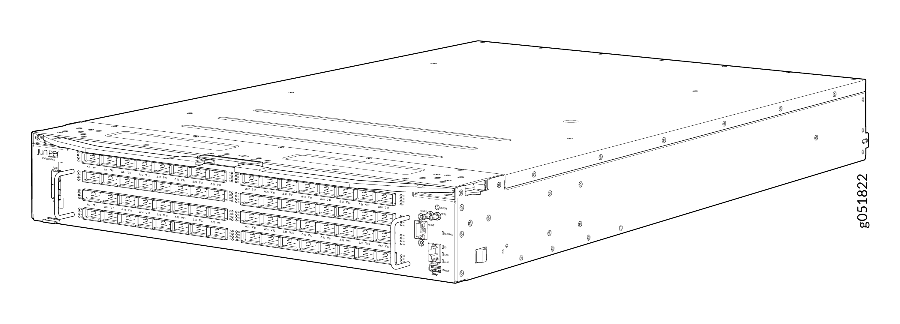
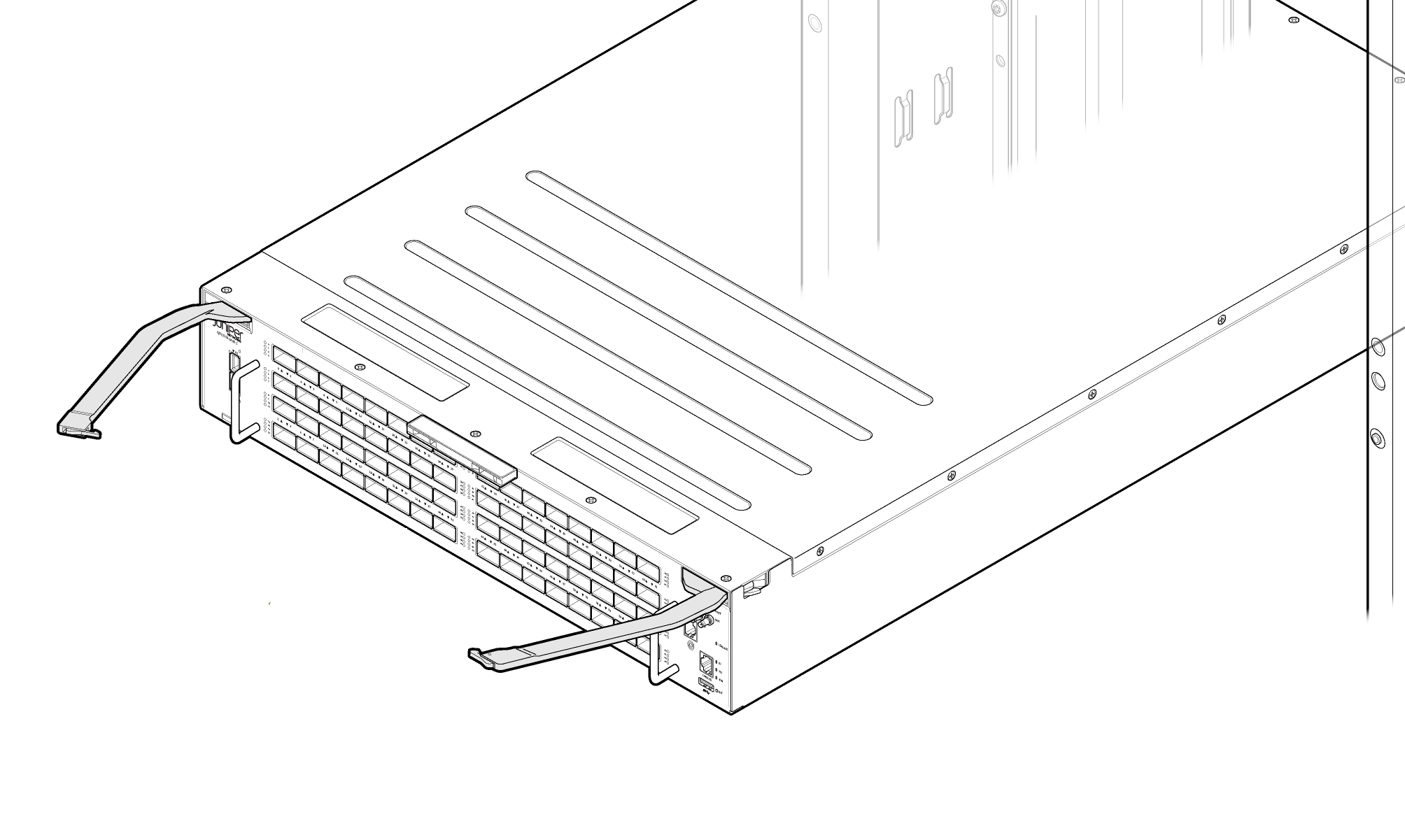
Remove the switch from shipping carton. See Figure 1.
Figure 1: QFX5250-64OE-L Switch
-
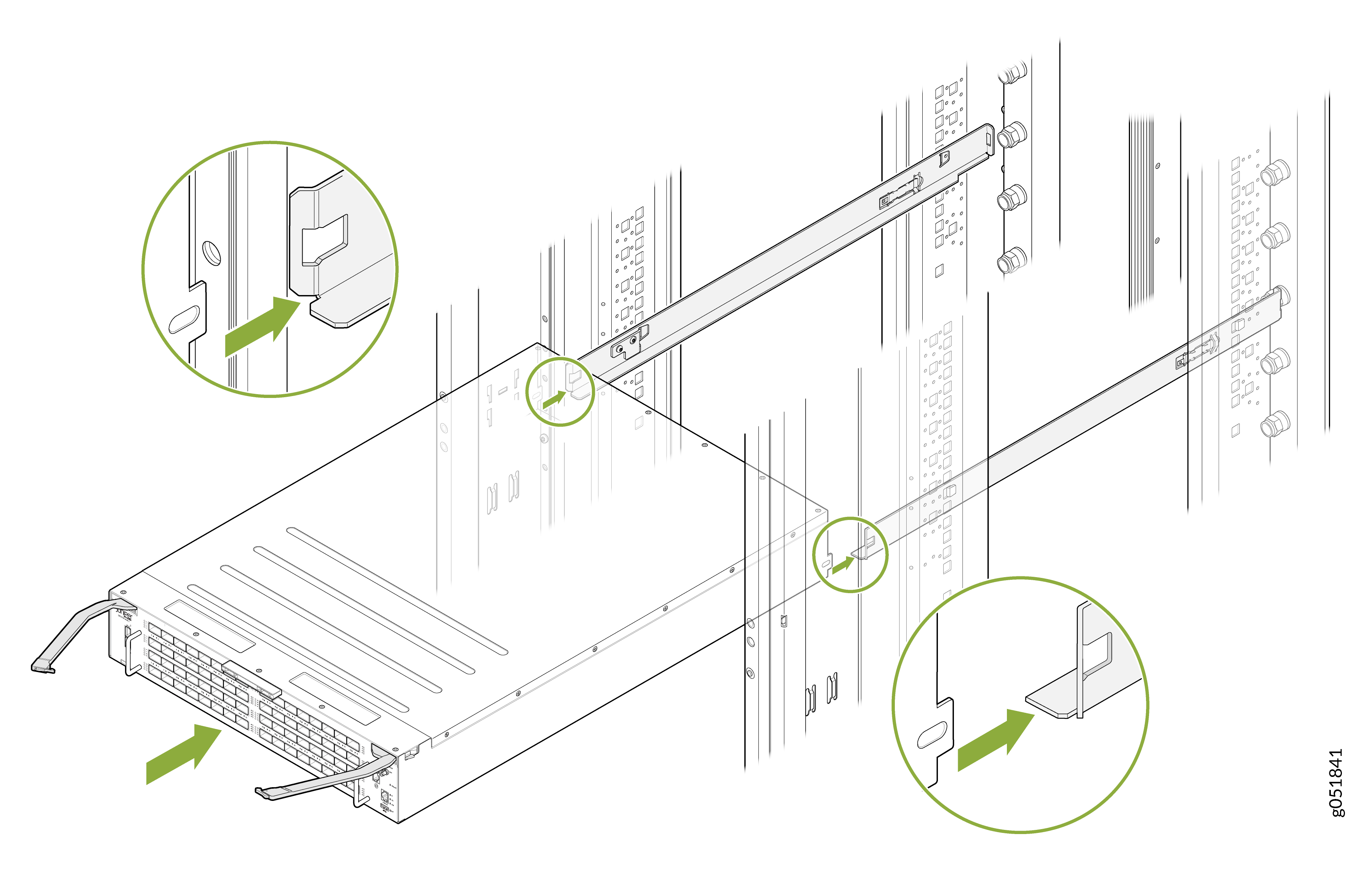
Align the rails and secure the rails in place on your ORv3 rack. See Figure 2
Figure 2: Align the Rails in ORv3 Rack
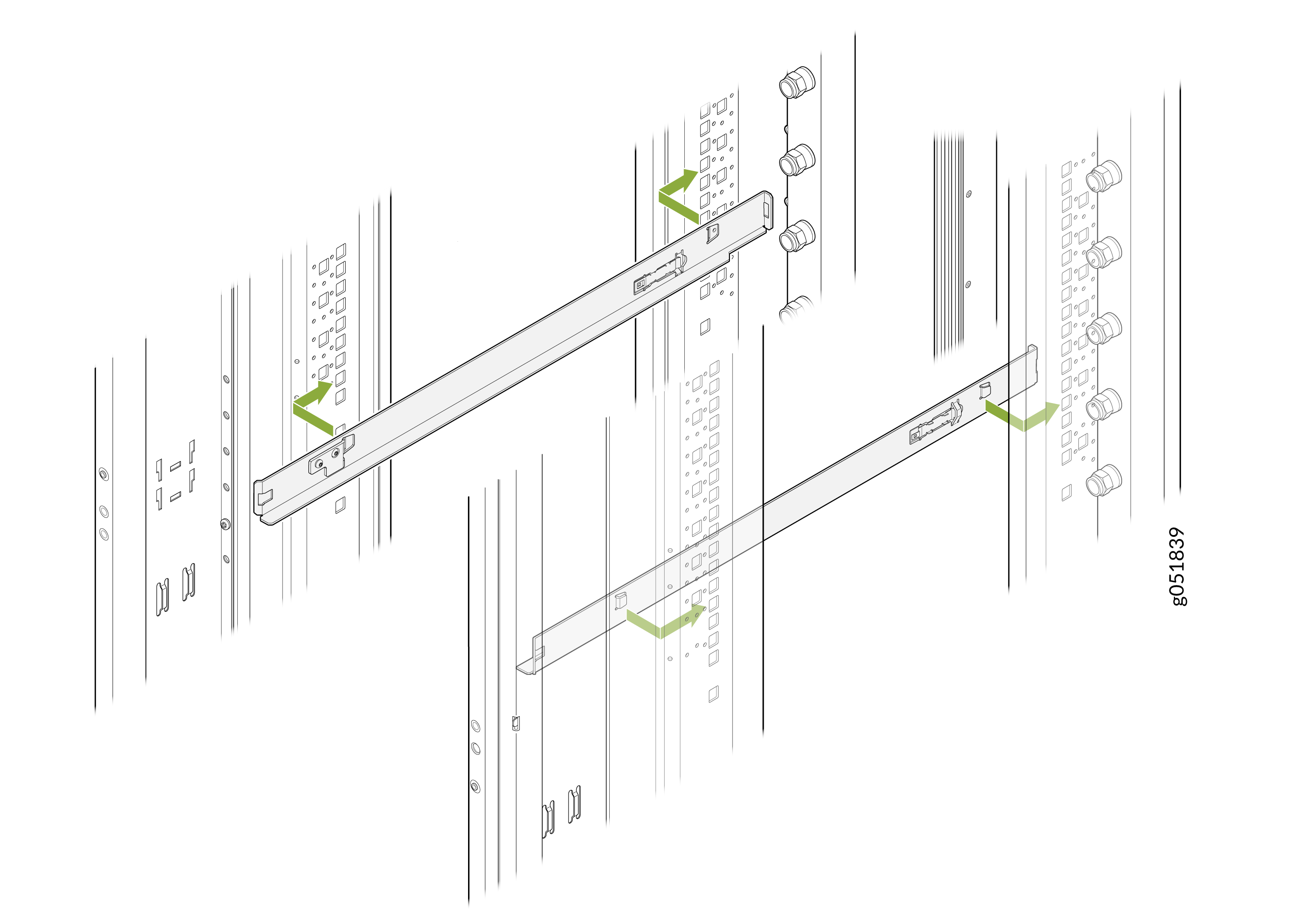 Note: Rails are not provided with the switch.Note:
You must use 1OU standard rails to install the 2OU QFX5250 liquid-cooled switches on ORv3 racks.
-
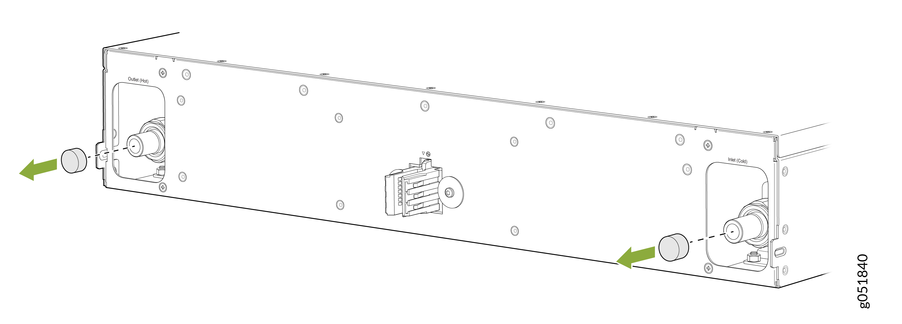
Remove the caps on the UQDB06 plugs on the switch for coolant inlet and
outlet from the ORv3 rack manifolds.
Figure 3: Remove the Caps on the Liquid Inlet and Outlet UQDB06 Plugs
-
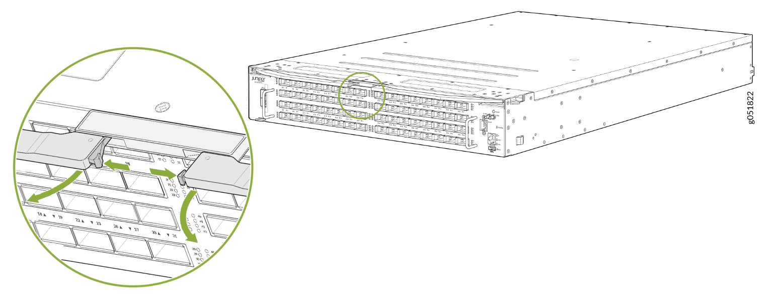
Press the push button on both ejector levers to release the ejector lock.
Note: Ensure that both ejector levers are opened together.Figure 4: Press the Push Button
-
Pull the ejector levers outward to the open position.
Figure 5: Switch Ejector Levers in Open Position
-
Carefully align the switch with the rails in the rack and slide the switch
into the rack. See Figure 6.
Figure 6: Slide the Switch into the Rack
-
Close the ejector levers inward and lock them on the front panel of the
switch. The IT Gear Input Connector at the rear of the switch fully engages
with the busbar.
Note: Ensure that both ejector levers are closed together.Note:
The internal coolant lines or tubes of the QFX5250 switch are shipped pre-filled with nitrogen. The nitrogen bleeds during the first rack installation. When liquid coolant enters the switch through the inlet UQDB06 plug and socket, the nitrogen in the tubing is displaced by the coolant. The displaced nitrogen is removed through the outlet UQDB06 plug of the switch.
Figure 7: Close the Ejector Levers on the Fully Inserted Switch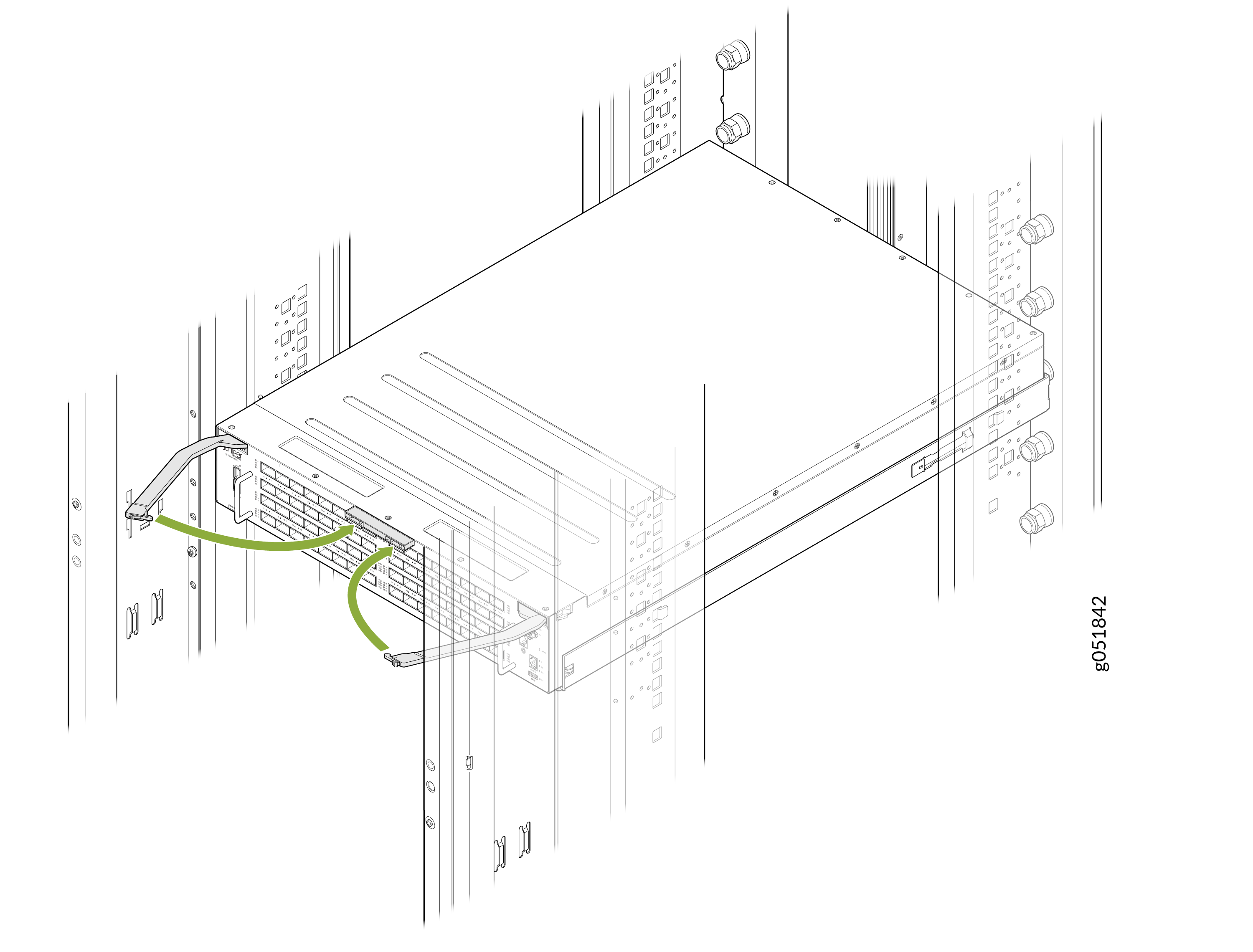 Note:
Note:The busbar on the ORv3 rack delivers power to the switch. The standard ORv3 rack used with the QFX5250 switch deliver an output voltage of 46 V DC to 56 V DC.
Uninstall the Switch from the ORv3 Rack
-
Locate the ejector levers in their closed position at the center of the
switch.
Figure 8: Locate the Ejector Levers
-
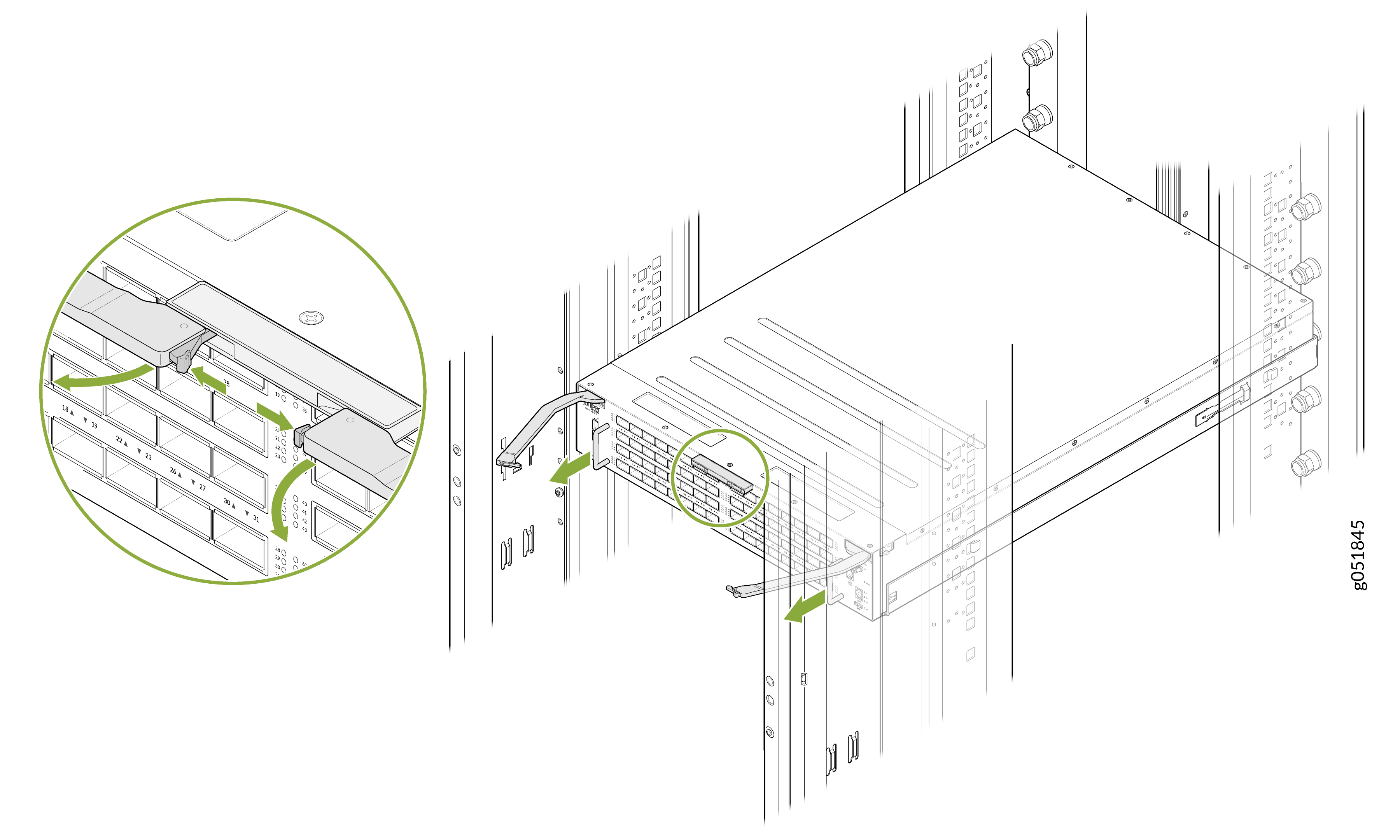
Grasp the handles on both sides of the switch and carefully slide the
switch out of the ORv3 rack. Sliding the switch out disconnects the power
supply to the switch.
Figure 9: Release the Ejector Lock and Slide the Switch Out
Ground the Switch
The ORv3 connector provides integrated grounding and no additional grounding is required.
You do not need separate grounding for your switch. The ORv3 rack infrastructure includes built-in grounding. Ensure the rack grounding is implemented according to site requirements. You do not need to take additional action for the switch.