QFX5250 Cooling System
The QFX5250 model that uses liquid-cooled system is:
-
QFX5250-64OE-L
Liquid Cooling in the QFX5250 Switch
The QFX5250 switch offers active cooling using liquid coolants. Active cooling is available for the liquid-cooled model QFX5250-64OE-L.
Liquid cooling is a thermal management system that uses a liquid coolant to absorb and remove heat from the switch and its components. The coolant is stored separately, outside the switch that is mounted on the ORv3 rack.
The storage and injection of coolant into the switch mounted on the ORv3 rack depends on the coolant storage and distribution system of the customer. However, in a typical rack-level cooling distribution system, the coolant is stored in a Coolant Distribution Unit (CDU) and circulated through the ORv3 racks using the inlet and outlet manifolds.
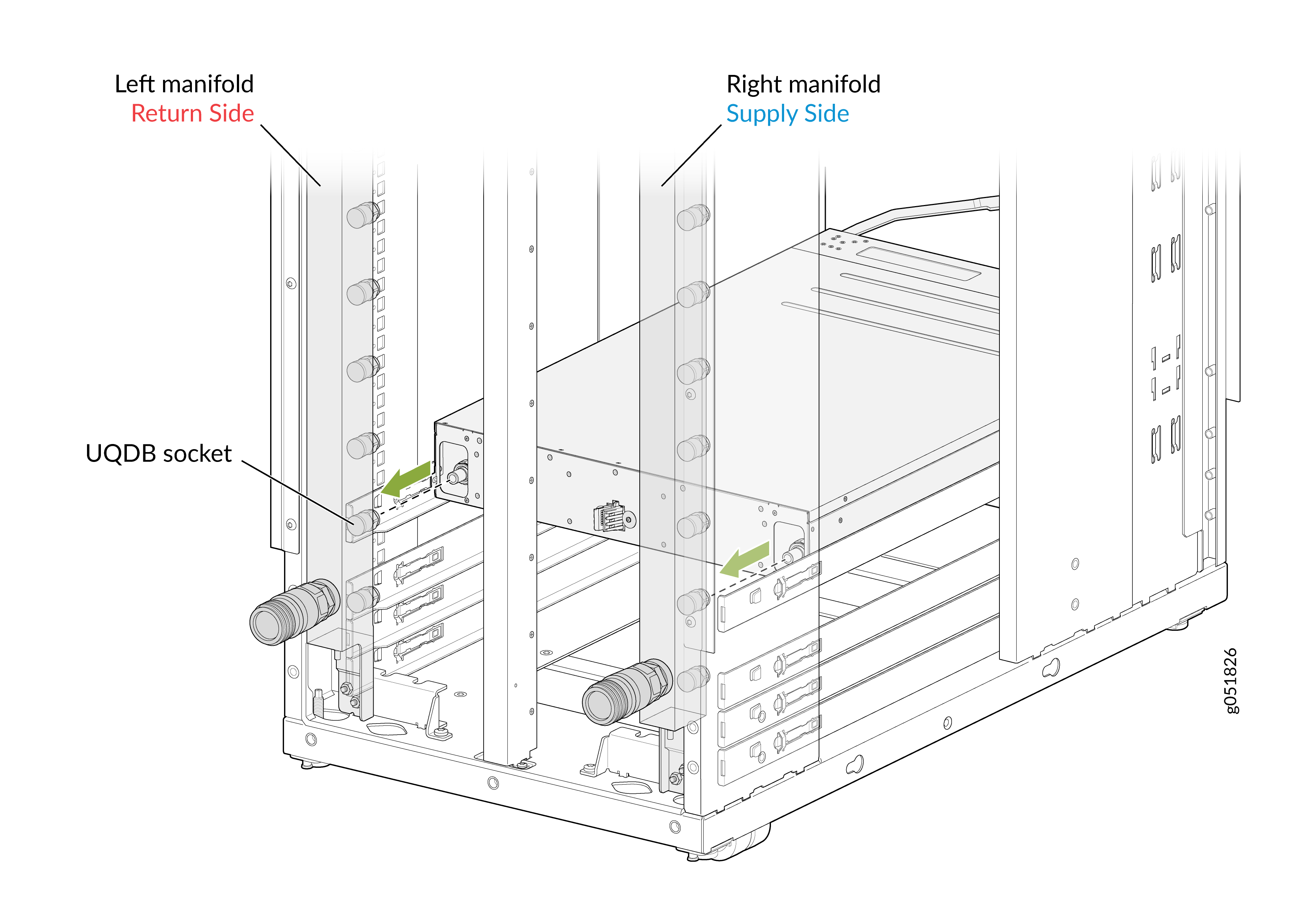
The inlet and outlet of liquid into the switch is governed by the Universal Quick Disconnect Blind-Mate (UQDB) standards. It is a global standard for quick disconnect blind-mate couplings developed within the OCP (Open Compute Project). UQDB functions as an open standard initiative for spill-free quick couplings for liquid cooling in data centers.
The UQDB06 inlet and outlet plugs on the switch blind-mate with the corresponding UQDB06 sockets on the inlet and outlet manifolds to form a UQDB06 plug and socket pair. During the installation of QFX5250 on an ORv3 rack, coupling occurs automatically.
The coolant is introduced from the rack manifold through UQDB06 sockets into the UQDB06 inlet plug in the QFX5250 switch. The coolant then circulates through the cold-plated components in the switch such as MAC, CPU, OSFP optics, and DC-to-DC power bricks. Using the tubing system in the switch, the coolant carries the heat out of the switch through the outlet UQDB06 plug and socket.
The cooling system consists of the following components:
-
Coolant—OAT PG 25 is the recommended coolant for QFX5250 Switch.
-
Tubing—Connects all the cold-plates in the switch through which the coolant is internally circulated.
-
Cold plate—A metal block with internal channels or passages through which liquid coolant flows. It acts as a heat exchanger that helps to remove the heat from the switch components using the coolant.
-
Inlet and outlet manifolds on ORv3 rack—The inlet manifold on the ORv3 rack pumps the coolant into the QFX5250 switch through the UQDB06 inlet plug. The outlet manifold removes the heat-carrying coolant from the switch through the UQDB06 outlet plug.
-
UQDB06 inlet and outlet sockets (on the ORv3 rack manifolds)—The UQDB06 inlet and outlet sockets allow the inlet and outlet of the coolant from the ORv3 rack manifold into the QFX5250 switch.
-
UQDB06 inlet and outlet plugs (on the QFX5250 switch chassis)—The UQDB06 plugs allow the inlet and outlet of the coolant into the switch from the UQDB06 sockets on the ORv3 rack manifold.
Note: The UQDB06 sockets on the rack manifold mates with the UQDB06 plugs on the liquid-cooled QFX5250 switch to ensure efficient coolant inlet and outlet. We recommend that you use the universal quick disconnect blind-mating parts from CEJN for QFX5250 switches.
ORv3 Rack Architecture for Liquid-Cooled Systems
ORv3 is a rack standard developed under the Open Compute Project (OCP). It has an open rack structure that supports high-density, liquid-cooled infrastructure. It integrates power distribution, liquid cooling, and compute into a single standardized rack architecture.
Based on your specific infrastructure needs, configuration may vary and you may not need all the components. This section outlines a typical ORv3 deployment.
- ORv3 rack—The rack enclosure that houses all compute, power, and cooling components in a structured, high-density format.
- Manifold—Mounted at the rear of the rack, the manifold distributes liquid coolant to and from the cold-plated switches in the rack.
- Busbar—A power distribution rail running along the rear of the rack, delivering 56 V DC through 46 V DC input voltage directly to the installed switches and components through the IT Gear Input Connector.
- Cold plates—Liquid-cooled plates that sit directly on heat-generating components of the switch and transfer heat to the circulating coolant, thereby helping to cool the switch.
- CDU (optional)—A coolant distribution unit that regulates and circulates liquid coolant within the rack.
- Centralized cooling or piping system—If a CDU is not used, cooling can alternatively be managed through a centralized cooling system that connects multiple racks to a facility-level cooling infrastructure.
Flow Rate Specifications
The components of the liquid cooling system work together to keep the switch within the acceptable temperature range. For a liquid-cooled system with cold-plated components and UQDB06 plugs and sockets, we recommend the following flow rates:
| Item | Specification | Notes |
|---|---|---|
|
Flow rate or capacity |
10 liters per minute |
The cooling system must have 10 liters of coolant passing through it every minute. |
|
Minimum liquid pressure rating |
25 PSI (pounds per square inch) |
The minimum operating pressure that the liquid-cooling system can safely handle. |
|
Maximum liquid pressure rating |
40 PSI (pounds per square inch) |
The maximum operating pressure that the liquid-cooling system can safely handle. |
|
Maximum coolant temperature |
45 °C |
The maximum temperature that the coolant maintains. |
|
Minimum coolant temperature |
7 °C |
The minimum temperature that the coolant maintains. |
|
Switch ambient temperature range |
0 °C through 40 °C |
The recommended operating temperature range for the liquid-cooled QFX5250 switch. |
The Leakage LED indicates the status of the liquid-cooling system in QFX5250:
|
Color |
State |
Description |
|---|---|---|
|
Unlit |
Off |
Normal operation with no leakage detected. |
|
Red Solid |
On steadily |
A leakage is detected and alarm has been triggered. |
Leakage Detection
One of the key considerations while using an active cooling system using liquid-cooling is to detect any coolant leakage in the switch. The coolant OAT PG 25 is electrically conductive. Whenever there is a leakage, the coolant comes in contact with the conductive layer or the sensing line in the switch. This forms a loop that can then be detected by the detection circuit.
After you install the switch on the rack and it receives stand-by power from the ORv3 rack, leakage detect circuitry monitors leakages and ensures that the LEAKAGE LED is lit red to notify you about an active leakage event. The boot operation is halted if a leakage is detected. Only on pressing the ON/OFF button, the QFX5250 switch proceeds with boot operation.
If no leakage is detected, the switch proceeds with normal boot operations.
After you inspect the QFX5250 switch and
conclude that there is no leakage, you can continue to operate the switch. At
this stage, the LEAKAGE LED could still be lit red. Use
the CLI command request system ldc leakage clear to clear the
leakage LED and leakage detect bit. This clears the leakage status until another
leakage event occurs. To know the latest status on leakage detect bit and
LEAKAGE LED, use the request system ldc
leakage status.
After you press the ON/OFF button, the switch boots and Leakage Detection Controller (LDC) becomes available. LDC monitors, detects, and reports coolant leakage for the switch for all successive stages of operation. LDC uses Redfish to trigger alarms.
Once the switch successfully boots up, Junos EVO also triggers alarms for leak detection. Junos EVO uses the gNMI network management protocol for leakage monitoring and alarms. Hence, both Junos EVO and LDC monitors and reports coolant leakage during the normal operation of QFX5250 switch.
The following are the different stages of the QFX5250 switch power-up sequence, and the corresponding leakage detection processes for each phase:
We do not recommend that you continue to operate a QFX5250 switch with leakage. If leakage is identified, you should return the switch to Juniper using the prescribed Return Materials Authorization (RMA) process. See Return a Hardware Component to Juniper Networks.
QFX5250 Pre-Power-On
Before powering on the QFX5250 switch, ensure the following:
-
ORv3 rack power is turned on.
-
The coolant supply from the centralized cooling distribution system (CDU) is turned on.
-
The QFX5250 chassis is installed in the ORv3 rack.
-
The inlet and outlet UQDB06 plugs on the switch are correctly mated with the corresponding inlet and outlet ports on the ORv3 rack manifold.
-
The coolant is flowing through the chassis.
Note:If coolant is not flowing through the chassis, temperature of the switch rises. It will be handled by Junos as per the Environment Monitoring (EM) policy.
Once you turn on the ORv3 rack power, 46 V to 56 V DC stand-by power is available to the switch. The QFX5250 switch uses this power to turn on the leakage detection circuitry in the switch. As soon as any leakage is detected, the LEAKAGE LED is lit red. Further, the power sequencing is halted. It allows you to remove the chassis from the ORv3 rack. If you wish to ignore the leakage detection and proceed with the power-on sequence, press the ON/OFF button for four seconds.
The QFX5250 chassis are hot-swappable. You can remove the chassis without turning off the ORv3 rack power.
QFX5250 Initialization
At the stage when the QFX5250 switch is initializing or booting up, the LDC of the switch is powered to be operational. If any leakage gets detected at this stage, then LDC notifies the user by generating an alarm over Redfish. Also, the leakage LED is lit red. To detect if any leakage occurs, the LDC continues to monitor the switch at fixed intervals of time.
QFX5250 Normal Operation
The LDC continues to monitor the device for leakage during normal operation. If a
leakage is detected during this phase, you receive an alarm notification from
LDC over Redfish. The leakage LED is lit red. The Junos EVO is operational in
this phase. It monitors and detects leakage using gNMI protocol. Use the command
show chassis alarms to display information about the
leakage conditions that Junos EVO detects and triggers alarms. If there is a
leakage, you are expected to shutdown the device. If the device is not shutdown,
you continue to receive the alarm notification about the leakage.
To clear the leakage LED or know the leakage LED status, see information on
request system ldc leakage clearand request system
ldc leakage status.
QFX5250 Switch Shutdown
When the QFX5250 switch is shut down, standby power is available from the ORv3 rack. Leakage detection is similar to the pre-power-on stage. At this stage, the leak detection circuit continuously monitors any leakage. As soon as any leakage is detected, the LEAKAGE LED is lit red.
Manifold Dimensions and Positions
The inlet and outlet manifolds run vertically along the rear of the ORv3 rack. They receive the coolant from the CDU or the centralized cooling system through coolant lines or hoses. The regularly spaced quick-connect ports along the manifold body are individual coolant tap-off points. Each corresponds to a rack unit position. This allows the liquid-cooled QFX5250 switch to connect its own inlet and outlet cooling UQDB06 plugs to the corresponding inlet and outlet quick-connect ports on the manifold. The following are the key dimensions of the manifold ports or UQDB06 sockets that align with the UQDB06 plugs:
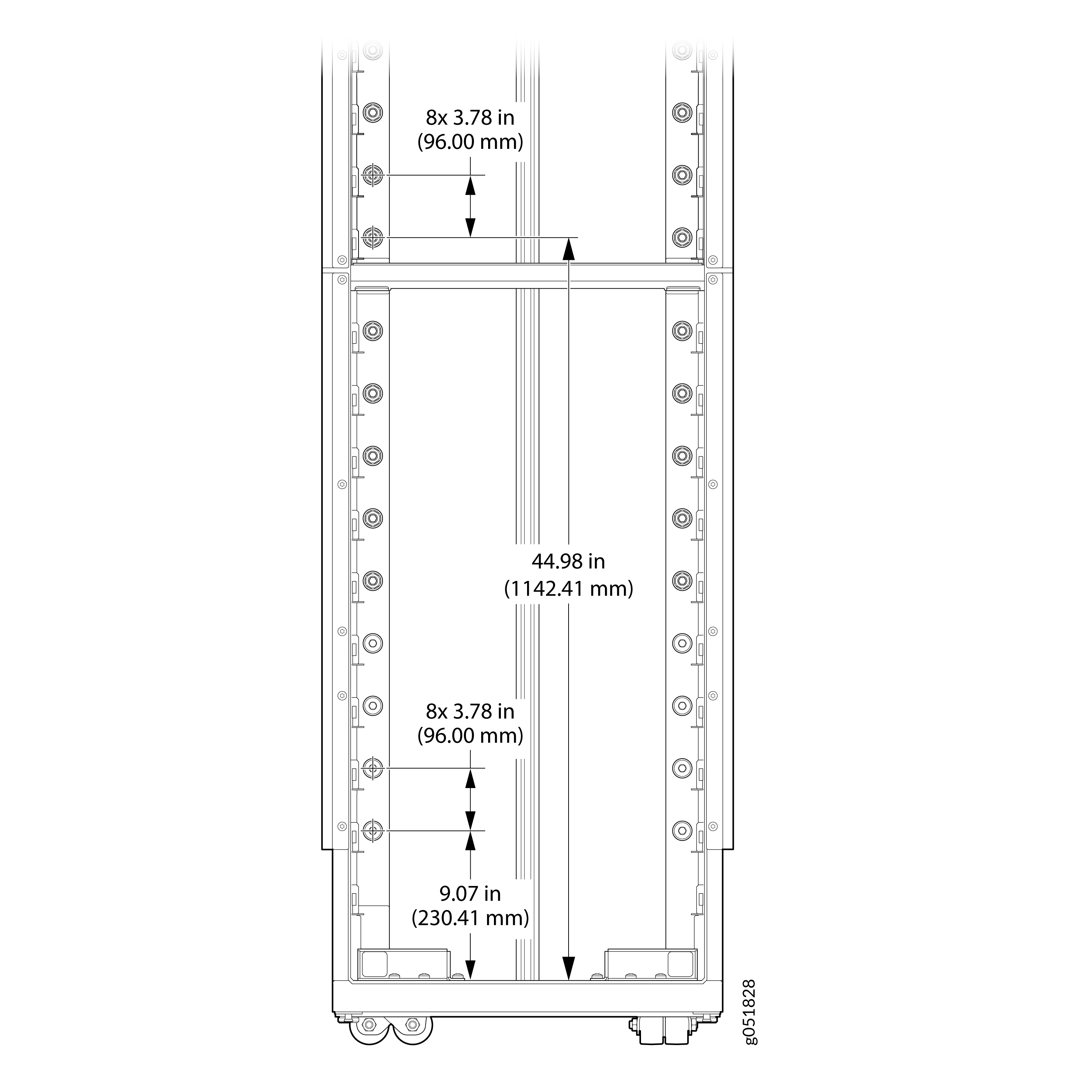
The rack base inner surface is treated as the datum.
-
Pitch between inlet manifold ports—96 mm
-
Pitch between outlet manifold ports—96 mm
-
Location of lowest UQDB06 mounting position—230.41 mm
-
Location of UQDB06 mounting position at the midpoint of the manifold—1142.41 mm