Connecting the QFX5200 to Power
Connect the QFX5200 to Earth Ground
You must install the QFX5200 in a restricted-access location and ensure that the chassis is always properly grounded. The QFX5200 has a two-hole protective grounding terminal provided on the chassis. See Figure 1. Under all circumstances, use this grounding connection to ground the chassis. For AC-powered systems, you must also use the grounding wire in the AC power cord along with the two-hole grounding lug connection. This tested system meets or exceeds all applicable EMC regulatory requirements with the two-hole protective grounding terminal.
Ensure that a licensed electrician has attached an appropriate grounding lug to the grounding cable that you supply. Using a grounding cable with an incorrectly attached lug can damage the switch (for example by causing a short circuit.)
Mount your switch in the rack or cabinet before attaching the grounding lug to the switch. See Unpacking and Mounting the QFX5200.
Ensure that you have the following parts and tools available:
Grounding cable for your QFX5200 device—The grounding cable must be 14 AWG (2 mm²), minimum 90° C wire, or as permitted by the local code (not provided).
(QFX5200-32C and QFX5200-32C-L) Grounding lug for your grounding cable—The grounding lug required is a Panduit LCD10-10A-L or equivalent (not provided).
For QFX5200-32C and QFX5200-32C-L, two 10-32 x 0.25 screws with #10 split-lock washers—Two screws are used to secure the grounding lug to the grounding lug bracket protective earthing terminal. These screws and washers are not provided.
For QFX5200-48Y, two 4.3 ring terminals, 14-18 AWG, and the provided M4 screw with star washer.
Number 2 screwdriver.
An AC-powered QFX5200 switch chassis gains additional grounding when you plug the power supply in the switch into a grounded AC power outlet by using an AC power cord appropriate for your geographical location. See QFX5200 Power Cord Specifications.
To connect earth ground to a QFX5200-32C or QFX5200-32C-L:
- Secure the grounding lug to the protective earthing terminal
with two screws and washers. See Figure 1.Figure 1: Connecting a Grounding Cable to a QFX5200-32C and QFX5200-32C-L
To connect earth ground to a QFX5200-48Y:
Ensure the rack is properly grounded and is in compliance with ETSI ETS 300 253.
Verify that there is a good electrical connection to the grounding point on the rack.
Attach the ring terminals to each end of the #14 AWG grounding wire.
Connect one of the ring terminals to the grounding point on the FRU panel.
Connect the other ring terminal to the rack ground.
Do not remove the earth connection until all power supply connections are disconnected.
Alternate Method to Ground QFX5200-32C-DC Systems
Ensure that you have the following parts and tools available to ground the chassis using this method:
M5 pan-head screw x .08 mm with integrated washer (not provided)
M5 lug (not provided)
12 AWG (2.5 mm²) standard wire, 90° C wire or heavier (not provided)
Number 2 screwdriver (not provided)
To connect earth ground to a QFX5200-32C-DC power supply:
Have a licensed electrician attached the M5 grounding lug to the grounding cable that you supply.
CAUTION:Using a grounding cable with an incorrectly attached lug can damage the switch.
Ensure that all grounding surfaces are clean and brought to a bright finish before grounding connections are made.
Connect one end of the grounding cable to a proper earth ground, such as the rack in which the switch is mounted.
Place the grounding lug that is attached to the grounding cable over the protective earthing terminal on the DC power supply.
Use a screwdriver to secure the grounding lug to the protective earthing terminal with a M5 pan-head screw with integrated washer.
Dress the grounding cable and ensure that it does not touch or block access to other device components and that it does not drape where people could trip over it.
We recommend that you connect earth ground to a QFX5110 DC chassis using the Connect the QFX5200 to Earth Ground method. However if you can’t access the chassis using the two-holed grounding lug, you can ground the chassis using the DC protective earthing terminal on the DC power supply.
The DC power supplies have a protective earthing terminal on the face that holds an M5 pan-head screw with integrated washer. See Figure 2.
1 — Shunt negative input terminals (-48V) | 5 — Protective earthing terminal |
2 — Shunt positive input terminals (+RTN) | 6 — Fault LED |
3 — Terminal block | 7 — Output LED |
4 — Security latch | 8 — Input LED |
Connecting AC Power to a QFX5200
Ensure that you have a power cord appropriate for your geographical location available to connect AC power to the switch.
Before you begin connecting AC power to the switch:
Ensure that you have taken the necessary precautions to prevent electrostatic discharge (ESD) damage (see Prevention of Electrostatic Discharge Damage).
Ensure that you have connected the switch chassis to earth ground.
CAUTION:Before you connect power to the switch, a licensed electrician must attach a cable lug to the grounding and power cables that you supply. A cable with an incorrectly attached lug can damage the switch (for example, by causing a short circuit).
To meet safety and electromagnetic interference (EMI) requirements and to ensure proper operation, you must connect the chassis to earth ground before you connect it to power. For installations that require a separate grounding conductor to the chassis, use the protective earthing terminal on the switch chassis to connect to the earth ground. For instructions on connecting earth ground, see Connect the QFX5200 to Earth Ground. The switch gains additional grounding when you plug the power supply in the switch into a grounded AC power outlet by using the AC power cord appropriate for your geographical location (see QFX5200 Power Cord Specifications).
Install the power supply in the chassis. For instructions on installing a power supply in a QFX5200, see Installing a Power Supply in a QFX5200.
The QFX5200 is shipped from the factory with two power supplies. Each power supply is a hot-removable and hot-insertable field-replaceable unit (FRU) when the second power supply is installed and running. You can install replacement power supplies in the two slots next to the fan modules without powering off the switch or disrupting the switching function.
Each power supply must be connected to a dedicated power source outlet.
To connect AC power to a QFX5200:
- For QFX5200-32C and QFX5200-32C-L models, push the power
cord retainer onto the power cord (see Figure 3). Power cord retainers
are not available for QFX5200-48Y PSUs.Figure 3: Connecting an AC Power Cord to an AC Power Supply in a QFX5200-32C and QFX5200-32C-L
 1—
1—Power cord retainer
Connecting DC Power to a QFX5200
The QFX5200 is shipped from the factory with two power supplies. Each power supply is a hot-removable and hot-insertable field-replaceable unit (FRU) when the second power supply is installed and running. You can install replacement power supplies in the two slots next to the fan modules without powering off the switch or disrupting the switching function.
A DC-powered QFX5200 is intended for installation only in a restricted access location.
The battery returns of the DC power supply must be connected as an isolated DC return (DC-I).
The QFX5200-32C-L is only available for AC.
This topic includes:
Before You Begin
Before you begin connecting DC power to the switch:
-
Ensure that you have taken the necessary precautions to prevent electrostatic discharge (ESD) damage (see Prevention of Electrostatic Discharge Damage).
-
Ensure that you have connected the switch chassis to earth ground.
CAUTION:Before you connect power to the switch, a licensed electrician must attach a cable lug to the grounding and power cables that you supply. A cable with an incorrectly attached lug can damage the switch (for example, by causing a short circuit).
To meet safety and electromagnetic interference (EMI) requirements and to ensure proper operation, you must connect the chassis to earth ground before you connect it to power. For installations that require a separate grounding conductor to the chassis, use the protective earthing terminal on the switch chassis to connect to the earth ground. For instructions on connecting earth ground, see Connect the QFX5200 to Earth Ground.
On QFX5200-32C-DC systems, you can also ground the chassis using the DC protective earthing terminal on the DC power supply as an alternate method. This method is useful if you are unable to access the chassis ground point by using the two-holed grounding lug, see Alternate Method to Ground QFX5200-32C-DC Systems.
-
Install the power supply in the chassis. For instructions on installing a power supply in a QFX5200, see Installing a Power Supply in a QFX5200.
Ensure that you have the following parts and tools available:
-
For QFX5200-32C–DC power source cables (14–16 AWG) with ring lug (Molex 190700069 or equivalent) (not provided)
-
For QFX5200-48Y–DC power source cables (12 AWG) with ring lug (provided)
-
Phillips (+) screwdriver, number 2 (not provided)
-
Multimeter (not provided)
Connecting DC Power to a QFX5200-32C-DC
To connect DC power to a QFX5200-32C:
-
Install heat-shrink tubing insulation around the power cables.
To install heat-shrink tubing:
-
Slide the tubing over the portion of the cable where it is attached to the lug barrel. Ensure that tubing covers the end of the wire and the barrel of the lug attached to it.
-
Shrink the tubing with a heat gun. Ensure that you heat all sides of the tubing evenly so that it shrinks around the cable tightly.
Figure 4 shows the steps to install heat-shrink tubing.
Note:Do not overheat the tubing.
Figure 4: How to Install Heat-Shrink Tubing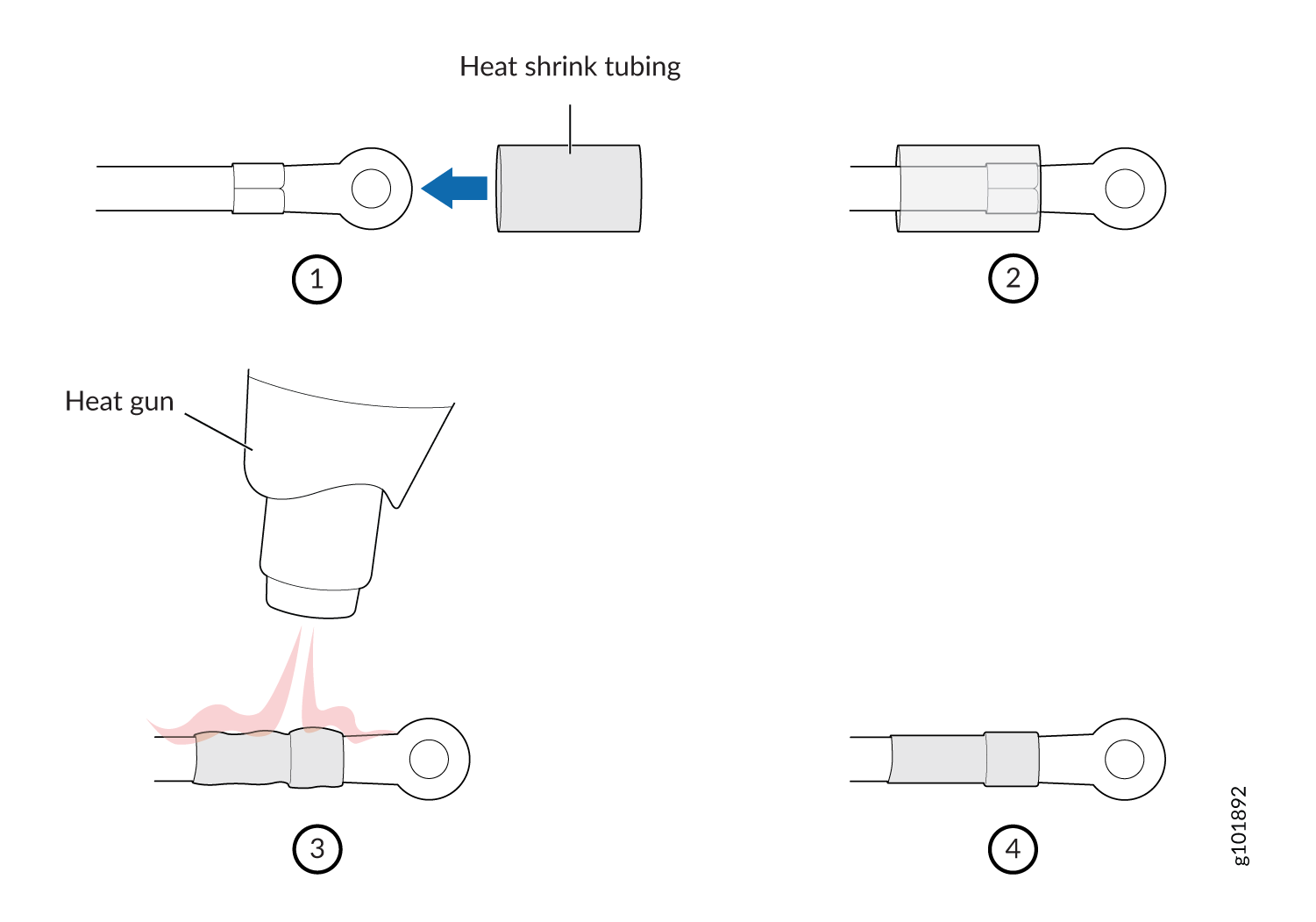
-
-
Connect each power supply to the power sources. Secure
power source cables to the power supplies by screwing the ring lugs
attached to the cables to the appropriate terminals by using the screw
from the terminals (see Figure 5and Figure 6 ).
The QFX5200-32C is designed to operate with a DC power supply that has a single, non-redundant, feed input. For source redundancy, two DC power supplies must be installed in QFX5200-32C; connect source (A) to one power supply and connect source (B) to the second power supply. This configuration provides the commonly deployed A/B feed redundancy for the system.
The terminal block of the power supply has four terminals labeled V+, V+, V–, and V– for connecting DC power source cables labeled positive (+) and negative (–). The V+ terminals are shunted internally together, as are the V- terminals.
CAUTION:The connection between each power source and power supply must include a circuit breaker.
Do not connect two sources to a single power supply because doing so can potentially cause circulating current in feed wires whenever there is any difference in the voltage of the two sources.
- Secure the ring lug of the positive (+) DC power source cable to the V+ terminal on the DC power supply.
- Secure the ring lug of the negative (–) DC power source cable to the V– terminal on the DC power supply.
- Tighten the screws on the power supply terminals until snug using the screwdriver. Do not overtighten—apply between 5 in-lb (0.56 Nm) and 6 in-lb (0.68 Nm) of torque to the screws.
Figure 5: QFX5200-32C-DC Faceplate 1—
1—Shunt negative input terminals (-48V)
5—Protective earthing terminal
2—Shunt positive input terminals (+RTN)
6—Fault LED
3—Terminal block
7—Output LED
4—Security latch
8—Input LED
CAUTION:The V+ terminals are shunted internally together, as are the V- terminals. The same polarity terminal can be wired together from the same source to provide an additional current path in a higher power chassis. Do not connect the terminals to different sources.
Figure 6: Securing Ring Lugs to the Terminals on the QFX5200-32C DC Power Supply 1—
1—Shunt negative input terminals (+RTN)
5—Protective earthing terminal
2—Shunt positive input terminals (-48V)
6—Fault LED
3—Terminal block
7—Output LED
4—Ejector lever
8—Input LED
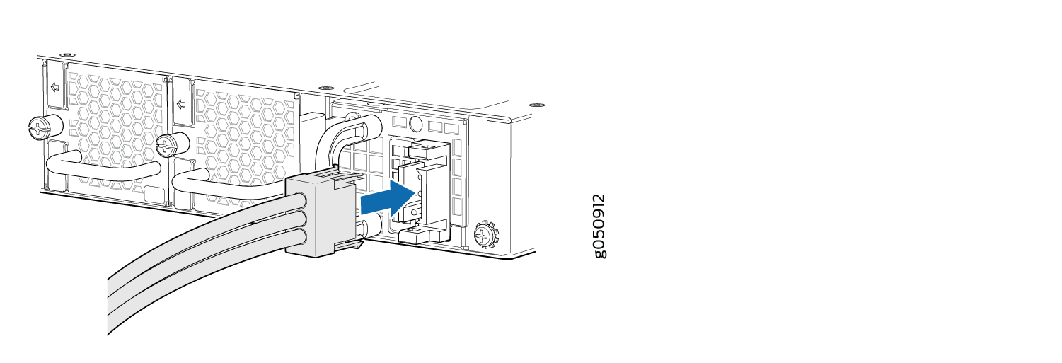
Connecting DC Power to a QFX5200-48Y
To connect DC power to a QFX5200-48Y:
-
.Connect each power supply to the power source by inserting
the DC connector of the provided power cable into the power supply.
See Figure 7.
Figure 7: Connecting DC Power Cable to QFX5200-48Y