QFX5200 Power System
QFX5200 AC Power Supply Description
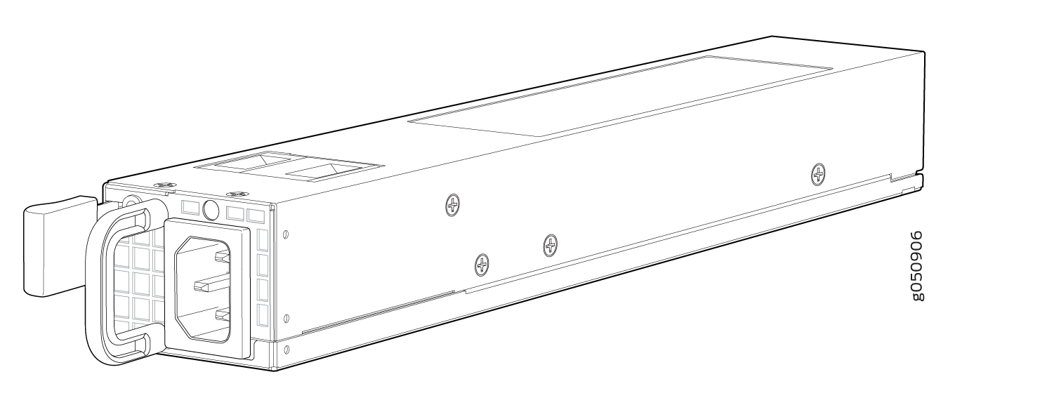
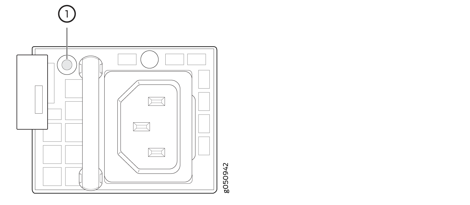
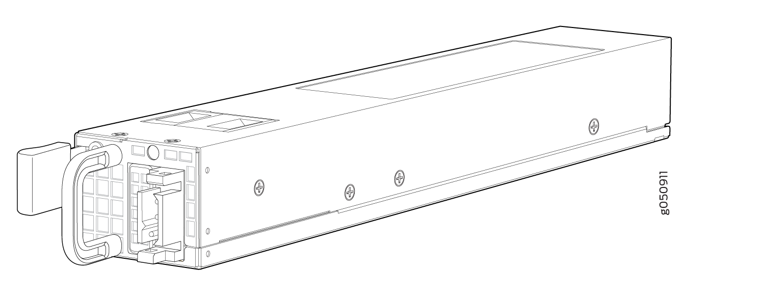
The two power supplies in QFX5200 are hot-removable and hot-insertable field-replaceable units (FRUs). The power supplies are installed in the switch at the factory. You can install replacement power supplies from the management panel without powering off the switch or disrupting the switching function. QFX5200 switches can operate with one PSU, but two power supplies are required to run without error messages and to have redundancy. See Figure 1 and Figure 2 for examples of QFX5200 AC power supplies.
The AC power supply in QFX5200-32C and QFX5200-32C-L switches is 850 W; the AC power supply in QFX5200-48Y switches is 650 W. Be sure to use the correct power supply for your chassis product SKU (see Table 1).
Do not mix power supplies with different airflow or different wattage. The system raises an alarm when a power supply having a different airflow or wattage is inserted into the chassis.
You may mix AC and DC power supplies with the same airflow in QFX5200-48Y, but load sharing is different between the two designs.
1 — Handle | 3 — AC appliance inlet |
2 — Security latch | 4 — Ejector lever |
The power supply provides FRU-to-port or port-to-FRU airflow depending on the product SKU you purchase. The power supplies have color-coded indicators to indicate the airflow direction. Either the PSU handle or the panel behind the handle are color-coded. See Figure 3 for an example of the QFX5200-32C and QFX5200-32C-L power supplies and Table 1 to determine the airflow of the PSU.
1 — Fan icon on handle |
|
Model |
Part Number |
Airflow Direction |
Color Indicator |
|---|---|---|---|
|
QFX5200-32C and QFX5200-32C-L |
JPSU-850W-AC-AFI |
Airflow In (FRU-to port) |
Juniper Azure Blue handle |
|
JPSU-850W-AC-AFO |
Airflow Out (port-to-FRU) |
Juniper Gold handle |
|
|
QFX5200-48Y |
QFX520048Y-APSU-AI |
Airflow In |
Blue panel |
|
QFX520048Y-APSU-AO |
Airflow Out |
Red panel |
Verify that the airflow direction on the power supply handle matches the direction of airflow in the chassis. Ensure that each power supply you install in the chassis has the same airflow direction. If you install power supplies with two different airflow directions, Junos OS raises an alarm. If you need to convert the airflow pattern on a chassis, you must change out all the fans and power supplies at one time to use the new direction.
To supply sufficient power, terminate the DC input wiring on a facility DC source that is capable of supplying a minimum of 7 A at –48 VDC.
To avoid electrical injury, carefully follow instructions in Connecting AC Power to a QFX5200.
QFX5200 AC Power Specifications
Table 2 describes the AC power specifications for a QFX5200.
Item |
Specification |
|
|---|---|---|
AC input voltage |
Operating range:
|
|
AC input line frequency |
50–60 Hz |
|
AC input current rating |
QFX5200-32C and QFX5200-32C-L |
4.5 A at 100–120 VAC 2.0 A at 200–240 VAC |
QFX5200-48Y |
7.8 A at 100–120 VAC 3.8 A at 200-240 VAC |
|
|
Typical power consumption |
QFX5200-32C |
200 W |
|
QFX5200-32C-L |
195 W | |
QFX5200-48Y |
382 W |
|
Maximum power consumption |
QFX5200-32C and QFX5200-32C-L |
312 W |
QFX5200-48Y |
430 W |
|
QFX5200 Power Cord Specifications
QFX5200 switches are now shipped with standardized PDU cables by default, designed for modern data centers that use IEC connector types. For customers operating in older data centers, earlier country‑specific power cables remain available.
| Country | Specifications | Shipped Power Cable | Graphic |
|---|---|---|---|
| All countries (International) |
Power Cord, AC, International(except India) C13, 10A, 250V, 2m, Straight, C13 to C14 |
CBL-C13-C14-INT-2M |
 |
| India | Power Cord, AC, India, C13, 10A, 250V, 2m, Straight, C13 to C14 |
CBL-C13-C14-IN-2M |
|
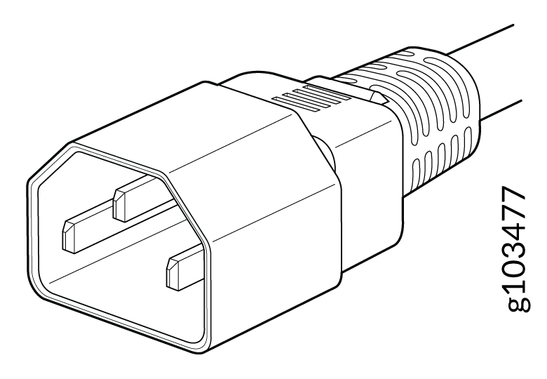
You can also order country-specific AC power cords separately if required. The coupler is type C13 as described by International Electrotechnical Commission (IEC) standard 60320. The plug end of the power cord fits into the power source outlet that is standard for your geographical location.
In North America, AC power cords must not exceed 14.75 feet (approximately 4.5 meters) in length, to comply with National Electrical Code (NEC) Sections 400-8 (NFPA 75, 5-2.2) and 210-52, and Canadian Electrical Code (CEC) Section 4-010(3). The cords that can be ordered for the QFX Series switches are in compliance.
Country/Region |
Electrical Specifications |
Plug Standards |
Juniper Model Number |
Spare Juniper Model Number |
Graphic |
|---|---|---|---|---|---|
Australia |
250 VAC, 10 A, 50 Hz |
AS/NZ 3109-1996 |
CG_CBL-C13-06-AU |
CBL-EX-PWR-C13-AU |
 |
Brazil |
250 VAC, 10 A, 50 Hz |
NBR 14136 Type BR/3 |
CBL-PWR-C15M-HITEMP-BR |
 |
|
China |
250 VAC, 10 A, 50 Hz |
GB 1002-1996 |
CG_CBL-C13-06-CH |
CBL-EX-PWR-C13-CH |
 |
Europe (except Italy, Switzerland, and United Kingdom) |
250 VAC, 10 A, 50 Hz |
CEE (7) VII |
CG_CBL-C13-06-EU |
CBL-EX-PWR-C13-EU |
 |
Israel |
250 VAC, 10 A, 50 Hz |
SI 32/1971 Type IL/3G |
CBL_CBL-C13-06-IL |
CBL-EX-PWR-C13-IL |
 |
Italy |
250 VAC, 10 A, 50 Hz |
CEI 23-16/VII |
CG_CBL-C13-06-IT |
CBL-EX-PWR-C13-IT |
 |
Japan |
125 VAC, 12 A, 50 Hz or 60 Hz |
JIS C8303 |
CG_CBL-C13-06-JP |
CBL-EX-PWR-C13-JP |
 |
North America |
125 VAC, 13 A, 60 Hz 250 VAC, 13 A, 60 Hz 250 VAC, 13 A, 60 Hz |
CAN/CSA No. 49-92 NEMA L6-15 NEMA 6-15 |
CG_CBL-C13-06-US |
CBL-EX-PWR-C13-US CBL-PW-C13-250-US CBL-PWR-C13-250-US |
 |
South Africa and India |
250 VAC, 10 A, 50 Hz |
SABS 164/1:1992 Type ZA/3 |
CBL-PWR-C15M-HITEMP-SA |
 |
|
South Korea |
250 VAC, 10 A, 60 Hz 250 VAC, 13 A, 60 Hz |
KSC 8305; K60884-1 |
CG_CBL-C13-06-KR |
CBL-EX-PWR-C13-KR |
|
Switzerland |
250 VAC, 10 A, 50 Hz |
SEV 1011 SEV 1991; EN 60320 C13 |
CG_CBL-C13-06-SZ |
CBL-EX-PWR-C13-SZ |
 |
Taiwan |
125 VAC, 11 A and 15 A, 50 Hz |
NEMA 5-15P Type N5-15P |
CG_CBL-C13-06-TW |
CBL-EX-PWR-C13-TW |
 |
United Kingdom |
250 VAC, 10 A, 50 Hz |
BS 1363/A |
CG_CBL-C13-06-UK |
CBL-EX-PWR-C13-UK |
|
QFX5200 AC Power Supply LEDs
The QFX5200-32C and QFX5200-32C-L uses three LEDs to indicate power status, while the QFX5200-48Y has a single bi-colored LED for power status.Figure 4 shows the location of the LEDs on the QFX5200-32C power supply. Figure 5 shows the LED location on a QFX5200-48Y power supply.
1 — Bi-colored LED |
Table 5 and Table 6 describe the LED behavior on the AC power supplies.
|
LED |
Color |
State |
Description |
|---|---|---|---|
|
AC OK |
Unlit |
Off |
The power supply is disconnected from power, or power is not coming into the power supply. |
|
Green |
On steadily |
Power is coming into the power supply. |
|
|
DC OK |
Unlit |
Off |
The power supply is disconnected from power, or the power supply is not sending out power correctly. |
|
Green |
On steadily |
The power supply is sending out power correctly. |
|
|
Fault |
Amber |
On steadily |
An error has been detected in the power supply. Replace the power supply as soon as possible. To maintain proper airflow through the chassis, leave the power supply installed in the chassis until you are ready to replace it. |
If the AC OK LED and the DC OK LED are unlit, either the AC power cord is not installed properly or the power supply fuse has failed. If the AC OK LED is lit and the DC OK LED is unlit, the AC power supply is installed properly, but the power supply has an internal failure.
|
Color |
State |
Description |
|---|---|---|
|
Unlit |
Off |
The power supply is disconnected from power, or power is not coming into the power supply. |
|
Green |
Blinking |
The PSU is in standby mode. Power is coming into the power supply at +5V.. |
|
On steadily |
The power supply is sending out power correctly. |
|
|
Alternating red/green |
Blinking |
Power supply warning. Check the logs for related messages. |
|
Red |
On steadily |
An error has been detected in the power supply. Replace the power supply as soon as possible. To maintain proper airflow through the chassis, leave the power supply installed in the chassis until you are ready to replace it. |
|
Blinking |
The internal fan in the power supply has failed. Replace the power supply as soon as possible. To maintain proper airflow through the chassis, leave the power supply installed in the chassis until you are ready to replace it. |
QFX5200 DC Power Supply Description
The power supplies in QFX5200 switches (see Figure 6 and Figure 7) are hot-removable and hot-insertable field-replaceable units (FRUs). You can install the power supplies without powering off the switch or disrupting the switching function. QFX5200 switches can operate with one PSU, but two power supplies are required to run without error messages and to have redundancy.
The DC power supply in QFX5200-32C is 1100 W with dual feeds for power resiliency.
1 — Terminal block | 3 — Ejector lever |
2 — Protective earthing terminal | 4 — Handle |
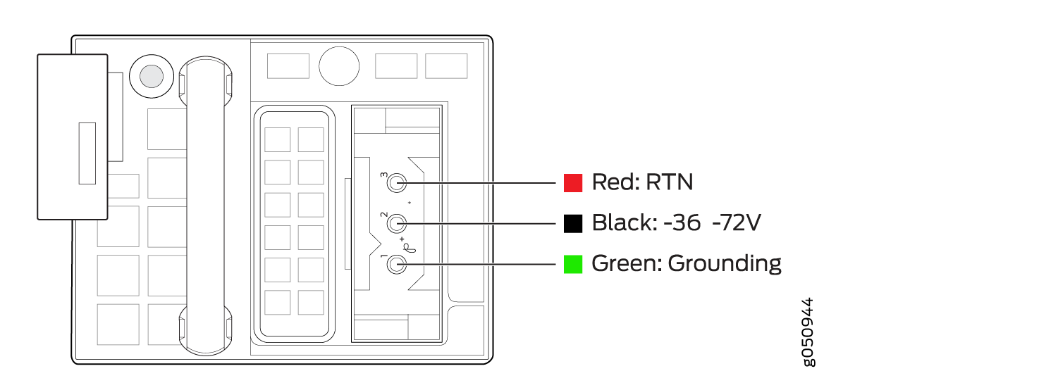
1 — Shunt negative input terminals (-48V) | 5 — Protective earthing terminal |
2 — Shunt positive input terminals (+RTN) | 6 — Fault LED |
3 — Terminal block | 7 — Output LED |
4 — Ejector lever | 8 — Input LED |
To avoid electrical injury, carefully follow instructions in Maintaining QFX5200 Power System.
QFX5200 DC Power Specifications
Table 7 describes the QFX5200 DC power specifications.
Item |
Model |
Specifications |
|---|---|---|
DC input voltage |
QFX5200-32C |
|
QFX5200-48Y |
Rated operating voltage: –48 VDC to -60 VDC |
|
DC input current rating |
QFX5200-32C |
10 A maximum |
QFX5200-48Y |
–48 VDC to –60 VDC: 21A –36 VDC to –72 VDC: 25A to 11A |
|
|
Typical power consumption |
QFX5200-32C |
200 W |
QFX5200-48Y |
315 W |
|
|
Maximum power consumption |
QFX5200-32C |
312 W |
QFX5200-48Y |
470 W |
QFX5200 DC Power Supply LEDs
Figure 10 and Figure 11 show the location of the LEDs on the QFX5200-32C DC power supply.
1 — Input LED | 3 — Fault LED |
2 — Output LED |
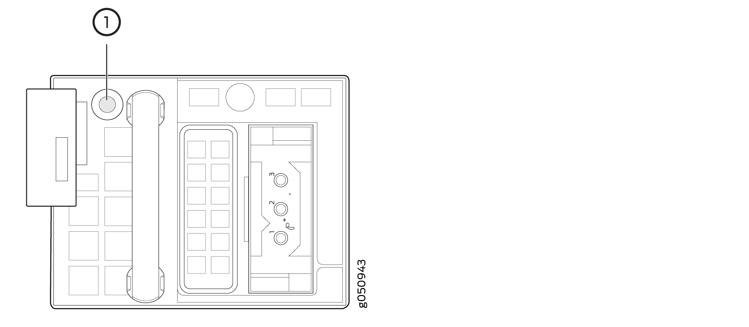
1 — Bi-colored LED |
The V+ terminals are shunted internally together, as are the V- terminals. The same polarity terminal can be wired together from the same source to provide an additional current path in a higher power chassis. Do not connect the terminals to different sources.
Table 8 and Table 9 describe the LEDs on the DC power supplies.
|
Name |
Color |
State |
Description |
|---|---|---|---|
|
Input |
Unlit |
Off |
The power supply is disconnected from power, or power is not coming into the power supply. |
|
Green |
On steadily |
Power is coming into the power supply. |
|
|
Output |
Unlit |
Off |
The power supply is disconnected from power, or the power supply is not sending out power correctly. |
|
Green |
On steadily |
The power supply is sending out power correctly. |
|
|
Fault |
Amber |
On steadily |
An error has been detected in the power supply. Replace the power supply as soon as possible. To maintain proper airflow through the chassis, leave the power supply installed in the chassis until you are ready to replace it. |
|
Color |
State |
Description |
|---|---|---|
|
Unlit |
Off |
The power supply is disconnected from power, or power is not coming into the power supply. |
|
Green |
Blinking |
The PSU is in standby mode. Power is coming into the power supply at +5V. |
|
On steadily |
The power supply is sending out power correctly. |
|
|
Alternating red/green |
Blinking |
Power supply warning. Check the logs for related messages. |
|
Red |
On steadily |
An error has been detected in the power supply. Replace the power supply as soon as possible. To maintain proper airflow through the chassis, leave the power supply installed in the chassis until you are ready to replace it. |
|
Blinking |
The internal fan in the power supply has failed. Replace the power supply as soon as possible. To maintain proper airflow through the chassis, leave the power supply installed in the chassis until you are ready to replace it. |