Unpacking and Mounting the QFX5200
Unpacking a QFX5200
The QFX5200 switch chassis is a rigid sheet-metal structure that houses the hardware components. A QFX5200 is shipped in a cardboard carton, secured with foam packing material. The carton also contains an accessory box and quick start instructions.
The QFX5200 is maximally protected inside the shipping carton. Do not unpack the switch until you are ready to begin installation.
To unpack a QFX5200:
|
Component |
Quantity |
|---|---|
|
Chassis with five or six fan modules and two power supplies |
1 |
|
Fan modules |
5 (QFX5200-32C or QFX5200-32C-L) 6 (QFX5200-48Y) |
|
Power supplies |
2 |
|
Rack mount kit for QFX5200-32C or QFX5200-32C-L - JNP-4PST-RMK-1U-E (Partial toolless RMK) JNP-4PST-RMK-1U-E rack mount kit consists of the following parts:
Spare rack mount kits order numbers:
|
1 |
|
Rack mount kit for QFX5200-48Y
The order number for a spare rack mount kit is QFX520048Y-RMKT. |
1
|
|
Rack mount assembly drawing |
1 |
|
Power cords with plugs appropriate to your geographical location |
2 |
|
Documentation roadmap card |
1 |
|
Warranty |
1 |
- RJ-45 to DB-9 adapter (JNP-CBL-RJ45-DB9)
- RJ-45 to USB-A adapter (JNP-CBL-RJ45-USBA)
- RJ-45 to USB-C adapter (JNP-CBL-RJ45-USBC)
If you want to use RJ-45 to USB-A or RJ-45 to USB-C adapter you must have X64 (64-Bit) Virtual COM port (VCP) driver installed on your PC. See, https://ftdichip.com/drivers/vcp-drivers/ to download the driver.
Update Base Installation Data
Update the installation base data if any addition or change to the installation base occurs or if the installation base is moved. Juniper Networks is not responsible for not meeting the hardware replacement SLA for products that do not have accurate installation base data.
Update your installation base at https://supportportal.juniper.net/s/CreateCase .
Mounting a QFX5200 in a Rack or Cabinet
You can mount all QFX5200 switches on a four post 19-in. rack or cabinet using the mounting kit provided with the switch.
The remainder of this topic uses “rack” to mean “rack or cabinet.” The front and rear rack rails must be spaced between 23.5 in. (59.7 cm) and 30.6 in. (77.7 cm) front to back.
This topic describes:
- Before You Begin Rack Installation
- Mount a QFX5200-32C or QFX5200-32C-L in a Rack or Cabinet by Using the EX-4PST-RMK Rack Mount Kit
- Mount a QFX5200-32C or QFX5200-32C-L in a Rack or Cabinet by Using the JNP-4PST-RMK-1U-E Rack Mount Kit
- Mount a QFX5200-48Y in a Rack or Cabinet by Using the QFX520048Y-RMKT Rack Mount Kit
Before You Begin Rack Installation
Before you begin mounting a QFX5200 switch in the rack or cabinet:
Optional equipment: Grounding cable kit with bracket, lug, and three nuts with integrated washers.
A QFX5200 switch must be supported at all four corners. Mounting the chassis using only the front brackets will damage the chassis and can result in serious bodily injury.
All QFX5200 switches require two people for installation, one person to lift the switch into place and another person to attach the switch to the rack. If you are installing the QFX5200 switch above 60 in. (152.4 cm) from the floor, you can remove the power supplies and fan modules to minimize the weight before attempting to install the switch.
If you are mounting multiple switches on a rack, mount the switch in the lowest position of the rack first. Proceed to mount the rest of the switches from the bottom to the top of the rack to minimize the risk of the rack toppling.
Mount a QFX5200-32C or QFX5200-32C-L in a Rack or Cabinet by Using the EX-4PST-RMK Rack Mount Kit
To mount the QFX5200-32C or QFX5200-32C-L on four posts in a rack by using the EX-4PST-RMK rack mount kit:
-
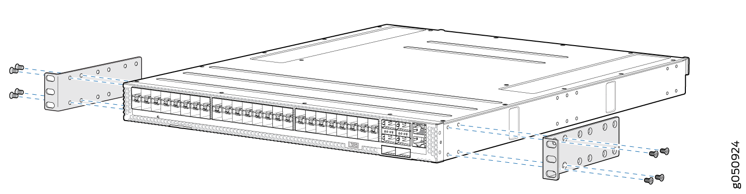
Align the holes in the mounting rail with the holes on the side of the
chassis. See Figure 1 to see the
proper alignment for the QFX5200-32C or QFX5200-32C-L switch.
Figure 1: Attaching Mounting Rails to the QFX5200-32C or QFX5200-32C-L
-
Have a second person secure the front of the switch to the rack using four
mounting screws (and cage nuts and washers if your rack requires them.)
Tighten the screws. See Figure 2 for an example of connecting the mounting rails and blades to a
QFX5200-32C or QFX5200-32C-L.
Figure 2: Attach QFX5200-32C or QFX5200-32C-L Switch to Rack
-
Continue to support the switch while sliding the rear mounting-blades into
the channel of the side mounting-rails and securing the blades to the rack.
Use the four mounting screws (and cage nuts and washers if your rack
requires them) to attach each blade to the rack. Tighten the screws. See
Figure 3.
Figure 3: Slide Mounting Blade into Mounting Rail
Mount a QFX5200-32C or QFX5200-32C-L in a Rack or Cabinet by Using the JNP-4PST-RMK-1U-E Rack Mount Kit
You can mount QFX5200-32C or QFX5200-32C-L switches on a square hole or threaded hole four-post 19-in. racks using the JNP-4PST-RMK-1U-E rack mount kit. A four-post installation evenly supports the switch by all four corners.
- Mount the Device by Using the JNP-4PST-RMK-1U-E Rack Mount Kit On a Square Hole Rack
- Mount the Device by Using the JNP-4PST-RMK-1U-E Rack Mount Kit On a Threaded Hole Rack
Mount the Device by Using the JNP-4PST-RMK-1U-E Rack Mount Kit On a Square Hole Rack
Ensure that you have the following tools and parts available:
-
An ESD grounding strap—not provided.
-
Number 2 Phillips (+) screwdriver—not provided
-
A pair of front and rear mounting rails that attach to the rack posts—provided with the rack mount kit
-
A pair of mounting brackets and 16 flat head M4 x 6mm Phillips screws. These brackets attach to the device if not pre-installed—provided with the rack mount kit
To mount the device on four posts in a rack by using the JNP-4PST-RMK-1U-E rack mount kit:
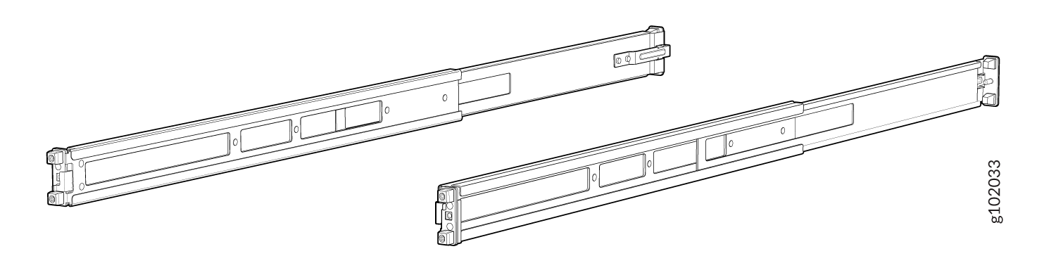
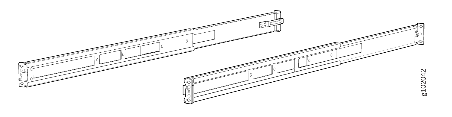
- Assemble the mounting rails.
-
Attach the mounting rails to the rack.
-
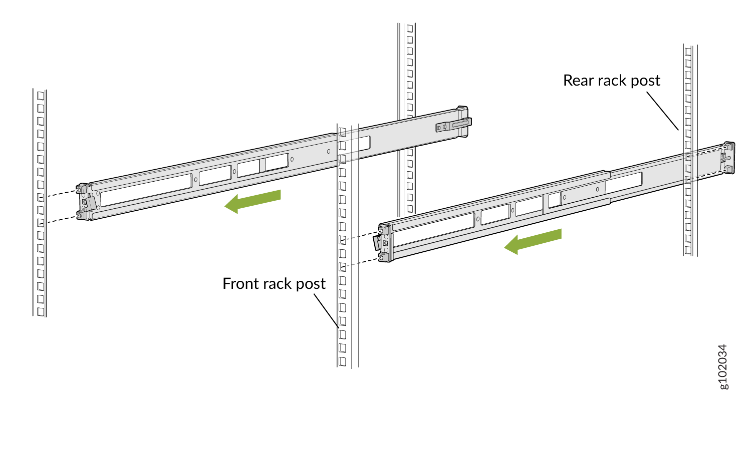
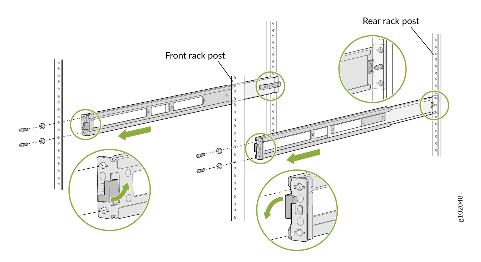
Align the guide blocks of the rear mounting rails with the rear-post holes. Pull
the rear mounting rails toward the front of the rack to lock the rails in place. You
will hear a click sound when the latch locks into the corresponding rack holes. See
Figure 6.
Figure 6: Install the Rear Floating Rails
-
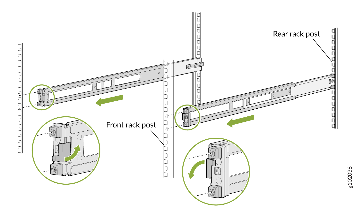
Move the latch lock on the front mounting rails to open position, slide the front
mounting rails, and insert the guide blocks into the front rack posts. See Figure 7.
Figure 7: Install the Front Mounting Rails
-
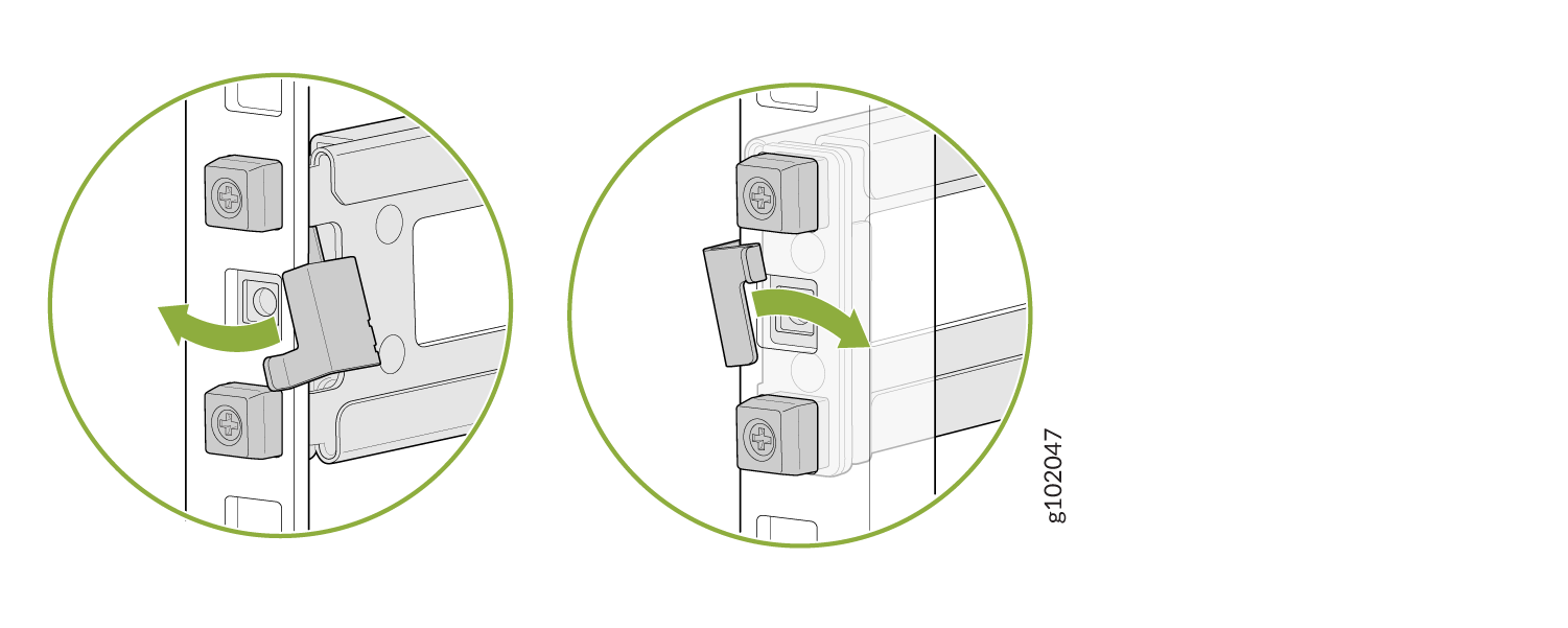
Push the lock latch to the locked position. See Figure 8.
Figure 8: Front Mounting Rails Lock Latch
-
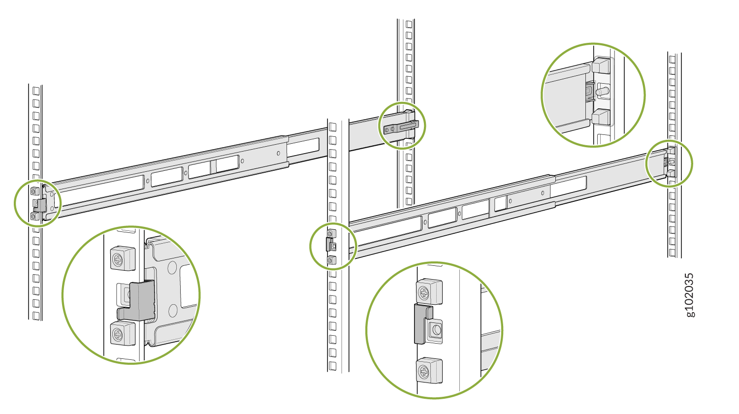
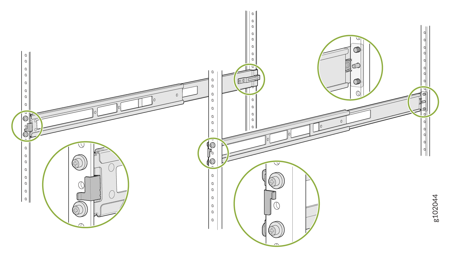
Visually ensure that the front and rear latches are locked into place on the
mounting rails. See Figure 9.
Figure 9: Mounting Rails Installed and Locked
-
Align the guide blocks of the rear mounting rails with the rear-post holes. Pull
the rear mounting rails toward the front of the rack to lock the rails in place. You
will hear a click sound when the latch locks into the corresponding rack holes. See
Figure 6.
-
Attach mounting brackets to the device if not pre-installed. If your device already has
the mounting brackets pre-installed than skip this step and move to the next step.
-
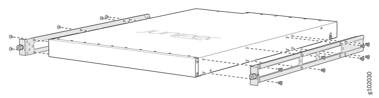
Insert the flat head M4 x 6mm Phillips screws to attach the mounting bracket into
the aligned holes on the chassis (see Figure 10). Tighten the screws.
Figure 10: Attach the Mounting Brackets to the Device
-
Insert the flat head M4 x 6mm Phillips screws to attach the mounting bracket into
the aligned holes on the chassis (see Figure 10). Tighten the screws.
-
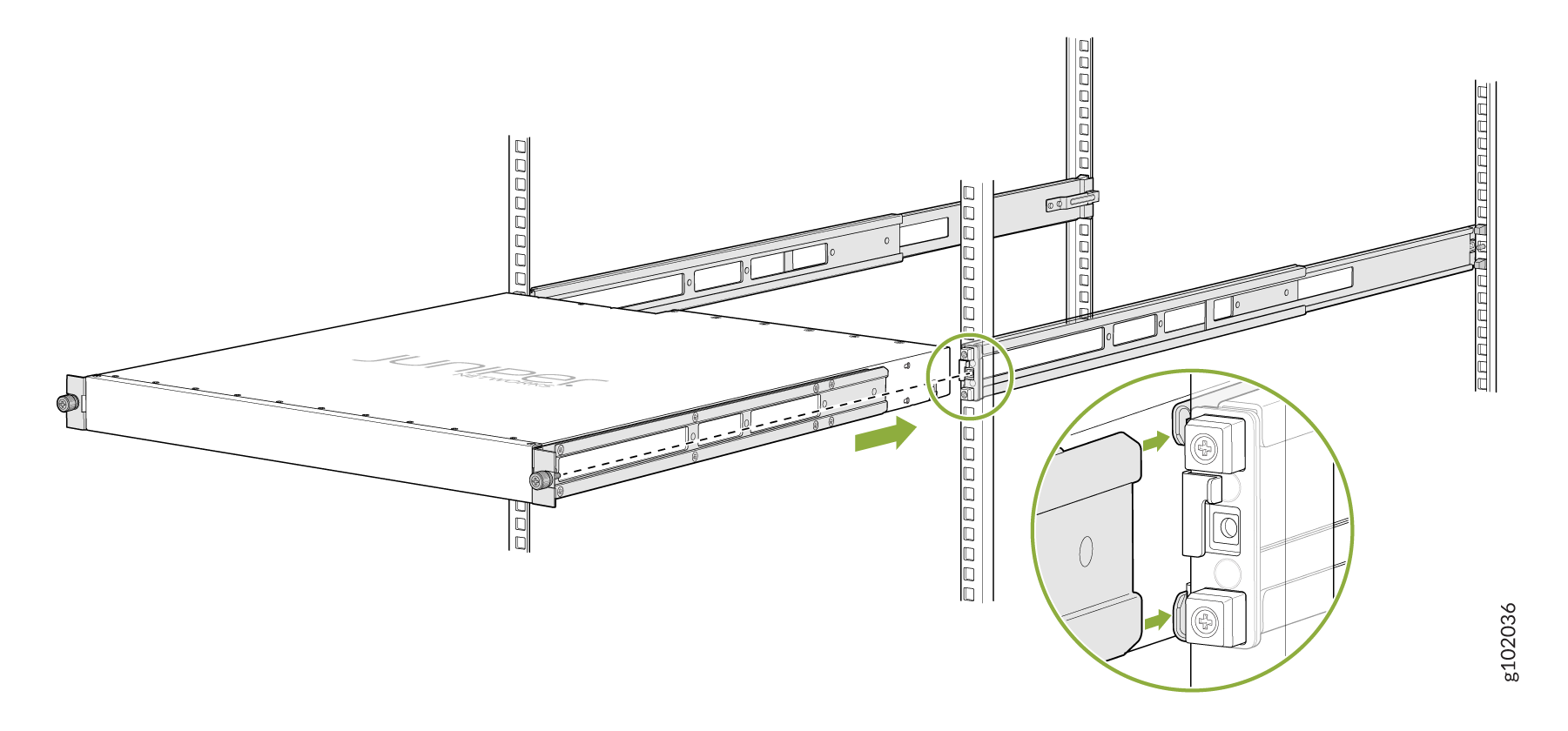
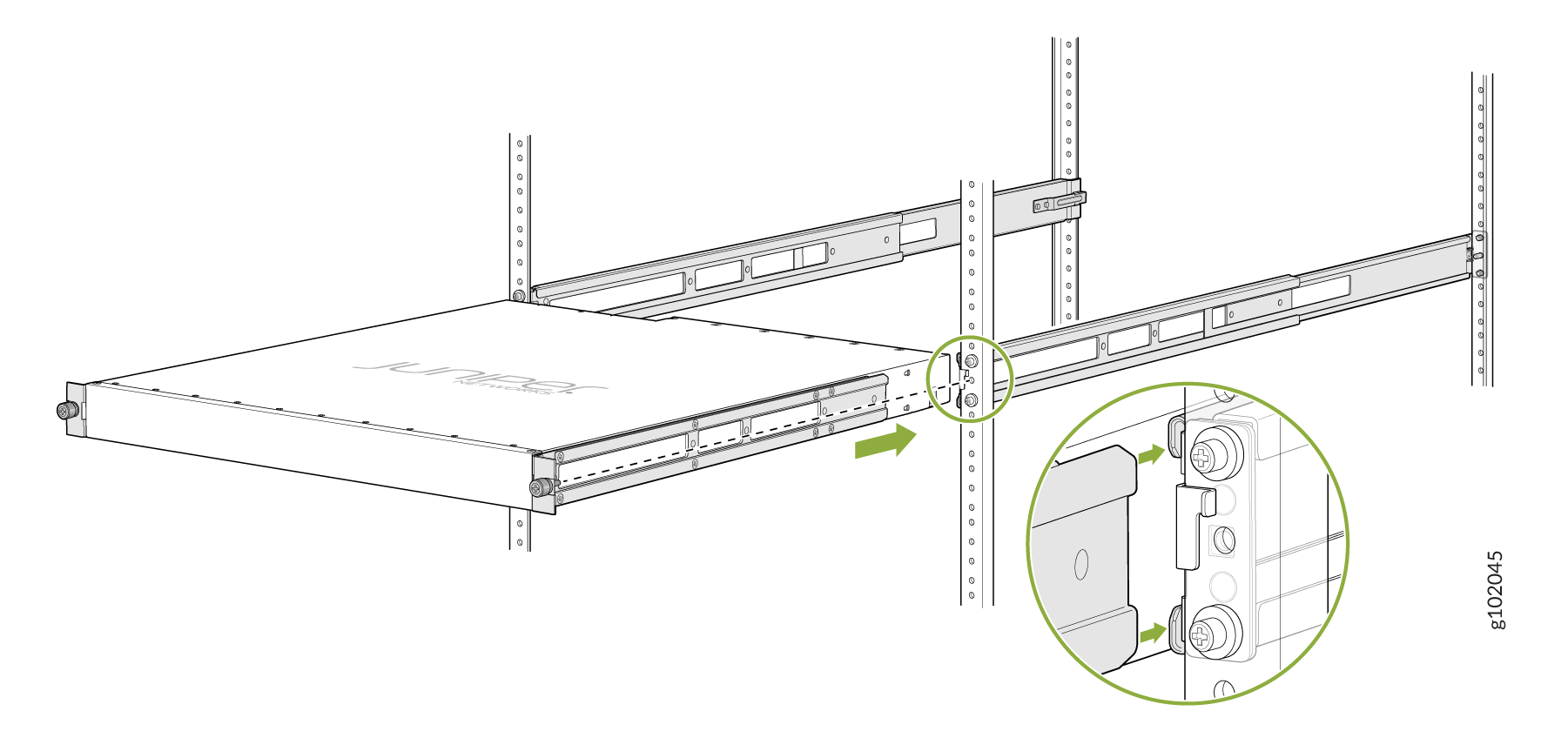
Grasp both sides of the device, lift it, and position the device such that the mounting
rails slide into the channels of the mounting brackets. See Figure 11.
Figure 11: Slide the Device into the Rack
-
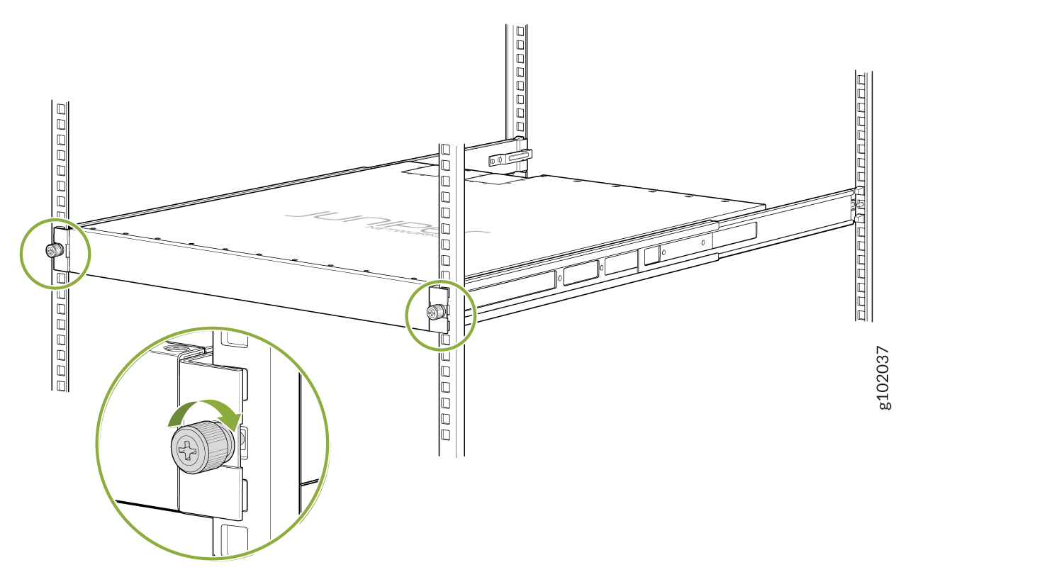
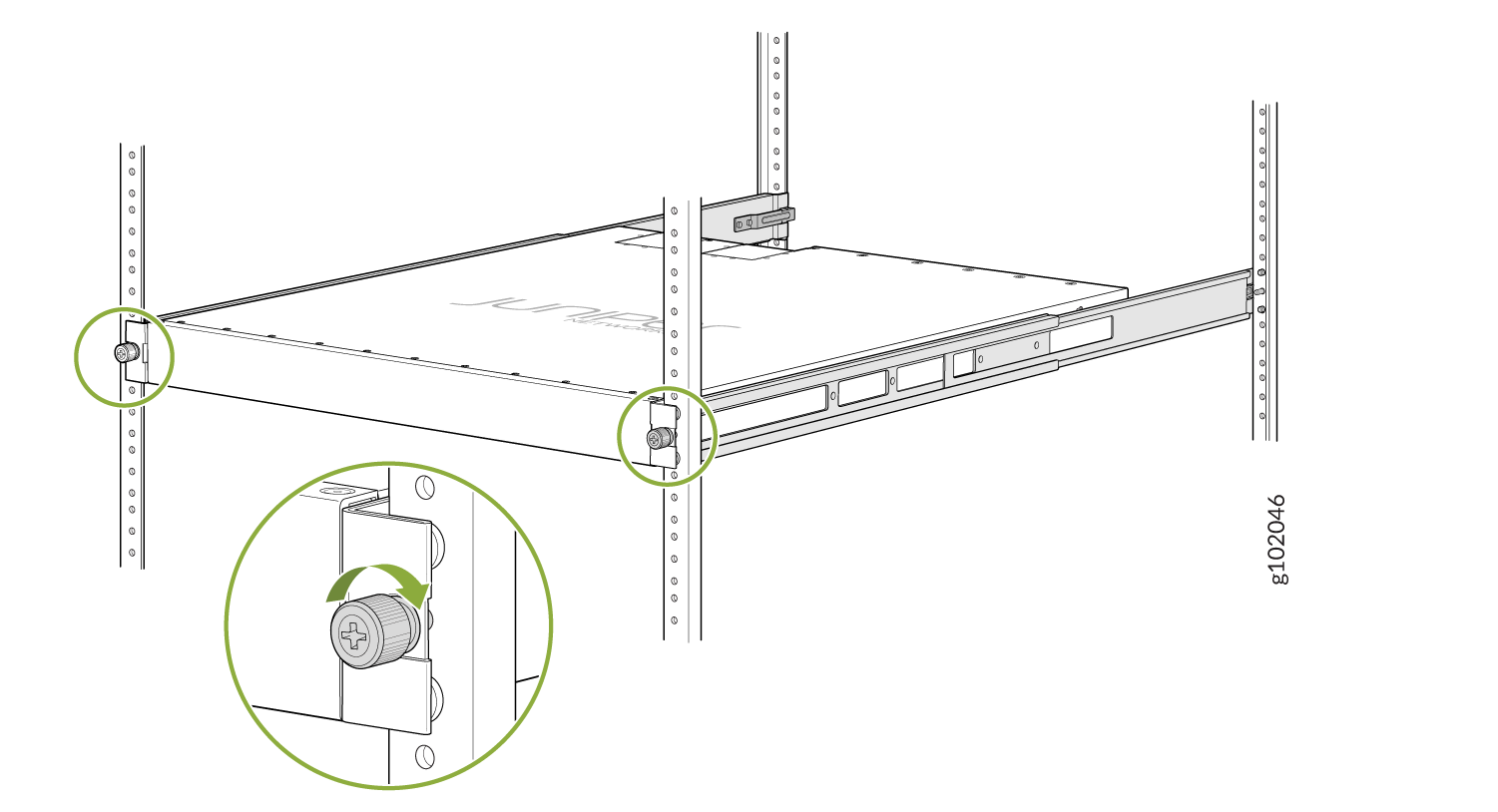
Tighten the two thumbscrews to secure the device. See Figure 12.
Figure 12: Tighten the Thumb Screws
Mount the Device by Using the JNP-4PST-RMK-1U-E Rack Mount Kit On a Threaded Hole Rack
Ensure that you have the following tools and parts available:
-
An ESD grounding strap—not provided
-
Number 2 Phillips (+) screwdriver—not provided
-
A pair of front and rear mounting rails that attach to the rack posts—provided with the rack mount kit
-
A pair of side mounting brackets and 16 flat head M4 x 6mm Phillips screws. These brackets attach to the device if not pre-installed—provided with the rack mount kit
To mount the device on four posts in a threaded hole rack by using the JNP-4PST-RMK-1U-E rack mount kit:
-
Assemble the mounting rails.
-
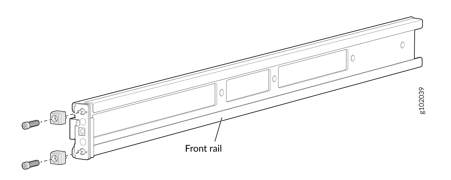
Remove the guide blocks from the front mounting rails by loosening the screws and
preserve them for later use. See Figure 13.
Figure 13: Remove Guide Blocks from Front Mounting Rail
-
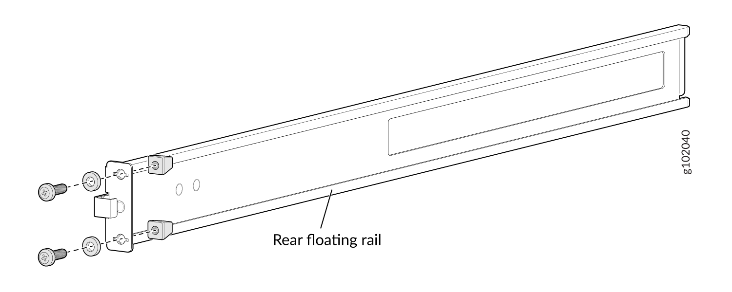
Remove the guide blocks from the rear floating rails by loosening the screws and
washers. Preserve the guide blocks, screws, and washers for later use. See Figure 14
Figure 14: Remove Guide Blocks from Rear Floating Rail
-
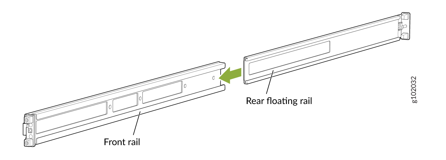
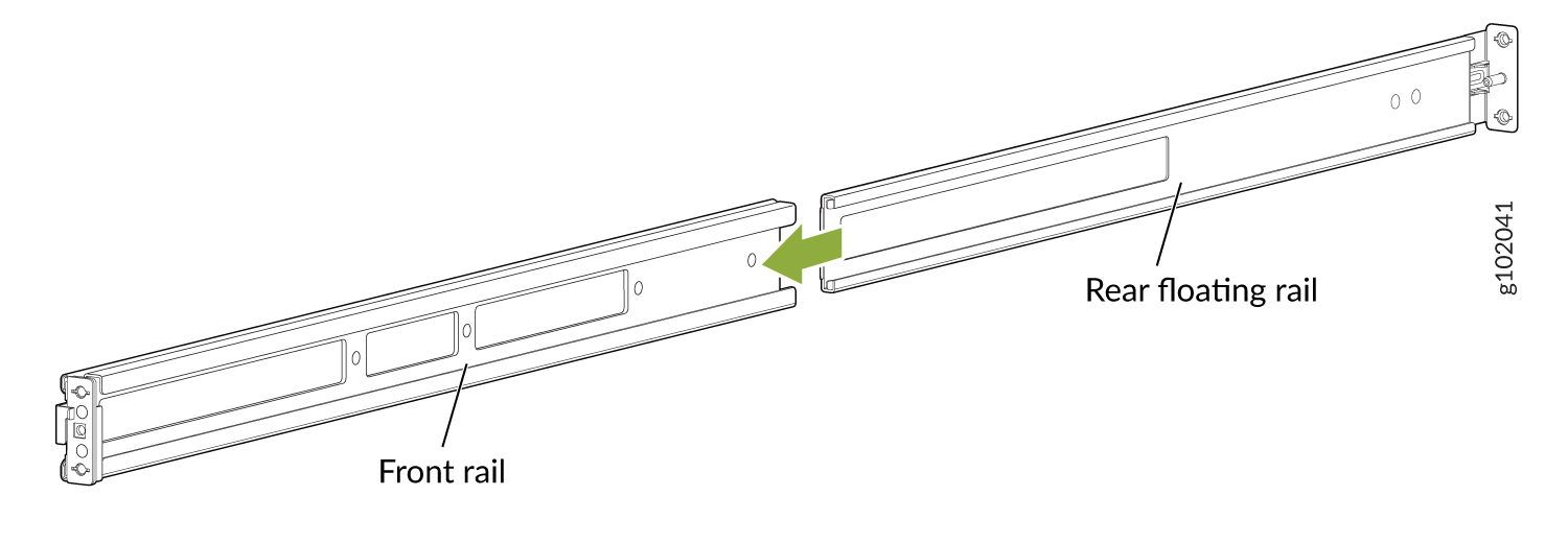
Slide the rear floating rails into the front mounting rails. See Figure 15.
Figure 15: Slide Rear Floating Rail into Front Mounting Rail
-
Mounting rails assembled. See Figure 16.
Figure 16: Front and Rear Rails Assembled
-
Remove the guide blocks from the front mounting rails by loosening the screws and
preserve them for later use. See Figure 13.
-
Attach the mounting rails to the threaded hole rack.
-
Align the guide blocks of the rear mounting rails with the rear-post holes. Pull
the rear mounting rails toward the front of the rack to lock the rails in place. You
will hear a click sound when the latch locks into the corresponding rack holes. See
Figure 17.
Figure 17: Install the Rear Floating Rails

-
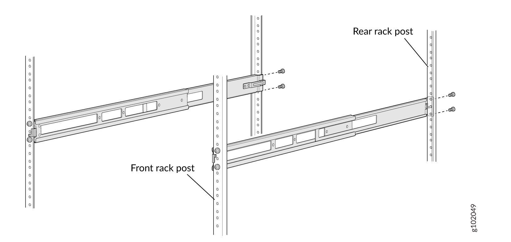
Move the latch locks on the front mounting rails to open position, slide the front
mounting rails and align them to the front rack post. Push the lock latch to locked
position and using the screws removed in step 2.a and
the washers removed in step 2.b,
secure the front mounting rails to the front rack post. See Figure 18.
Figure 18: Install the Front Mounting Rails
-
Secure the rear floating rails to the rear rack post by using screws (not provided)
appropriate for your rack threaded size. See Figure 19.
Figure 19: Secure the Rear Floating Rails
-
Visually ensure that the front and rear latches are locked into place on the
mounting rails. See Figure 20.
Figure 20: Mounting Rails Installed and Secured
-
Align the guide blocks of the rear mounting rails with the rear-post holes. Pull
the rear mounting rails toward the front of the rack to lock the rails in place. You
will hear a click sound when the latch locks into the corresponding rack holes. See
Figure 17.
-
Attach mounting brackets to the device if not pre-installed. If your device already has
the mounting brackets pre-installed than skip this step and move to the next step.
-
Insert the flat head M4 x 6mm Phillips screws to attach the mounting bracket into
the aligned holes on the chassis (see Figure 21). Tighten the screws.
Figure 21: Attach the Mounting Brackets to the Device
-
Insert the flat head M4 x 6mm Phillips screws to attach the mounting bracket into
the aligned holes on the chassis (see Figure 21). Tighten the screws.
-
Grasp both sides of the device, lift it, and position the device such that the mounting
rails slide into the channels of the mounting brackets. See Figure 22.
Figure 22: Slide the Device into the Rack
-
Tighten the two thumbscrews to secure the device. See Figure 23.
Figure 23: Tighten Thumb Screws
Mount a QFX5200-48Y in a Rack or Cabinet by Using the QFX520048Y-RMKT Rack Mount Kit
To mount the QFX5200-48Y on four posts in a rack by using the QFX520048Y-RMKT rack mount kit:
-
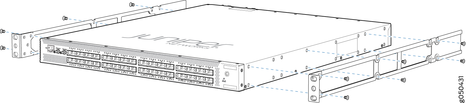
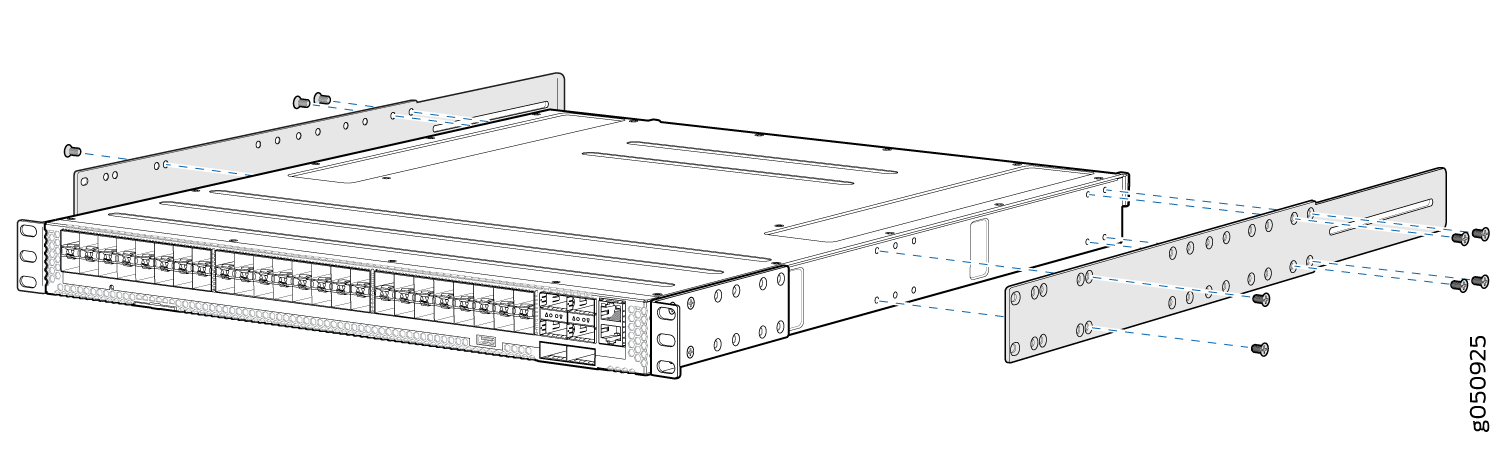
Align the holes in the front mounting bracket with the holes on the side of
the chassis so that the bracket is flush with the port panel. See Figure 24.
Figure 24: Align the Front Mounting Bracket and Secure with Screws
-
Attach the adjustable mounting rail to the chassis using the Phillips
screwdriver and six of the flat head screws. Tighten the screws. See Figure 25.
Figure 25: Align Holes for Mounting Rail and Attach with Screws
-
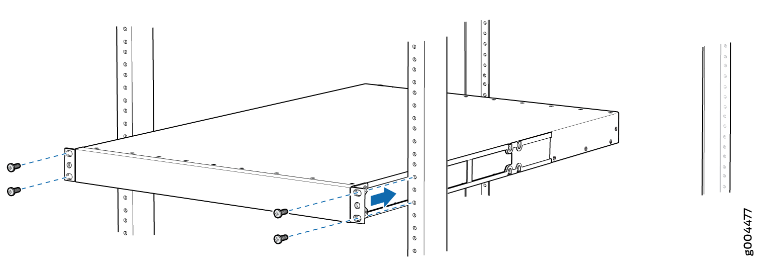
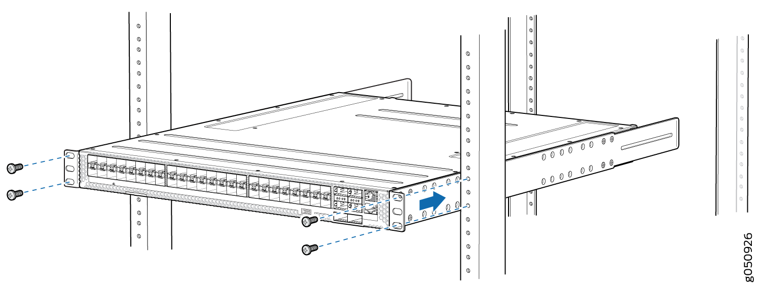
Have a second person secure the front of the device to the rack using four
mounting screws (and cage nuts and washers if your rack requires them).
Tighten the screws. See Figure 26.
Figure 26: Attach the Front Mounting Bracket to the Rack
-
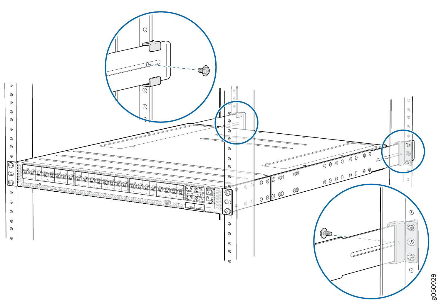
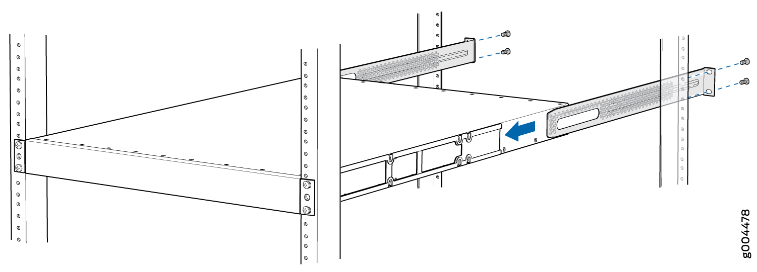
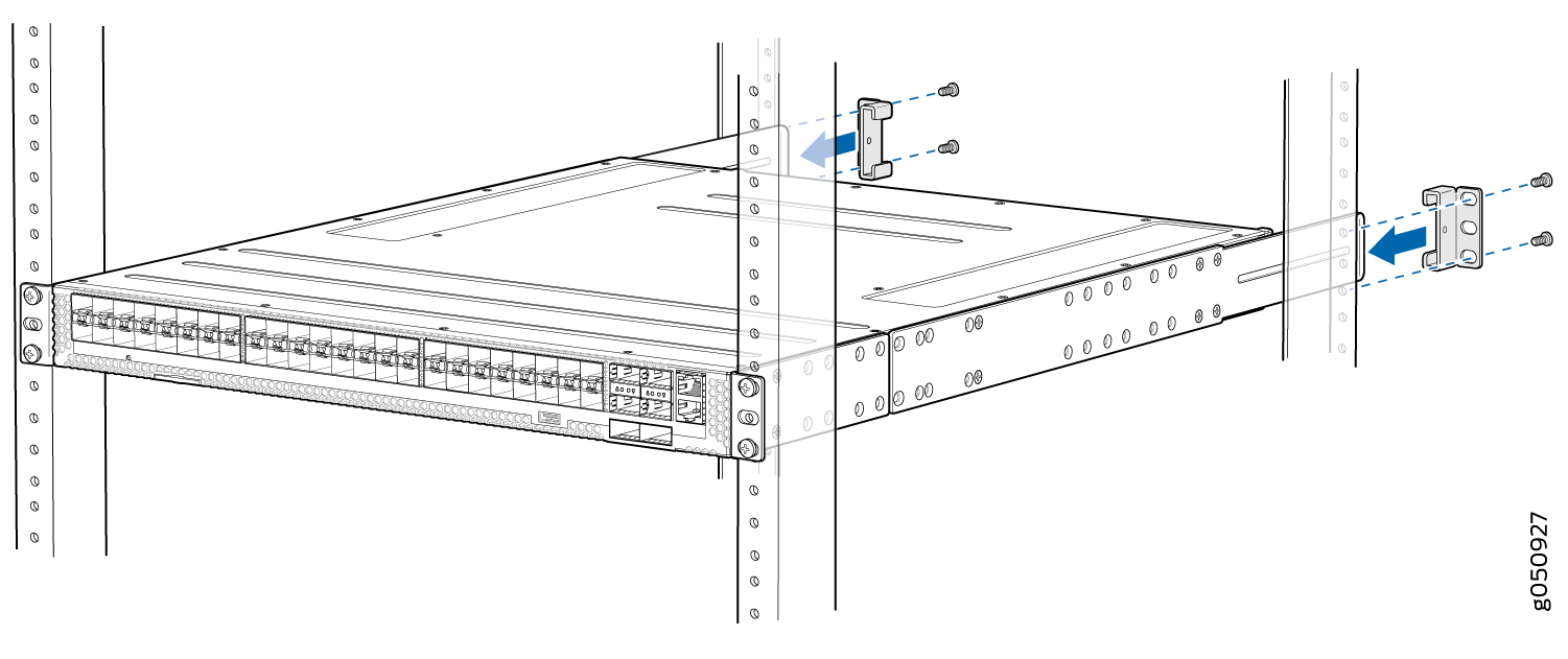
Continue to support the switch while sliding the rear mounting brackets
into the channel of the adjustable mounting blades and securing the blades
and the brackets to the rack. Use four mounting screws (and cage nuts and
washers if your rack requires them) to attach the blades and rear mounting
brackets to the rack. Tighten the screws. See Figure 27.
Figure 27: Slide Blades into Mounting Rails and Attach to the Rack
-
Secure the mounting rails to the rear mounting brackets using the two
washer head screws. Tighten the screws. See Figure 28.
Figure 28: Lock the Mounting Rails to the Rack