Help us improve your experience.

Let us know what you think.

Do you have time for a two-minute survey?


Unpacking the QFX10016

To unpack the QFX10016 and its components refer to the following sections:

Unpacking the QFX10016 Chassis

After you prepare the installation site as described in QFX10008 Site Preparation Checklist, you can unpack the switch.

Note:

The chassis is maximally protected inside the shipping box. Do not unpack it until you are ready to begin installation.

Ensure that you have the following parts and tools available to unpack the QFX10016:

  • A 13/32 in. (10 mm) open-end or socket wrench to remove the bracket bolts from the shipping pallet

  • A box cutter or packing knife to slice open the nylon straps and tape that seal the crate and boxes

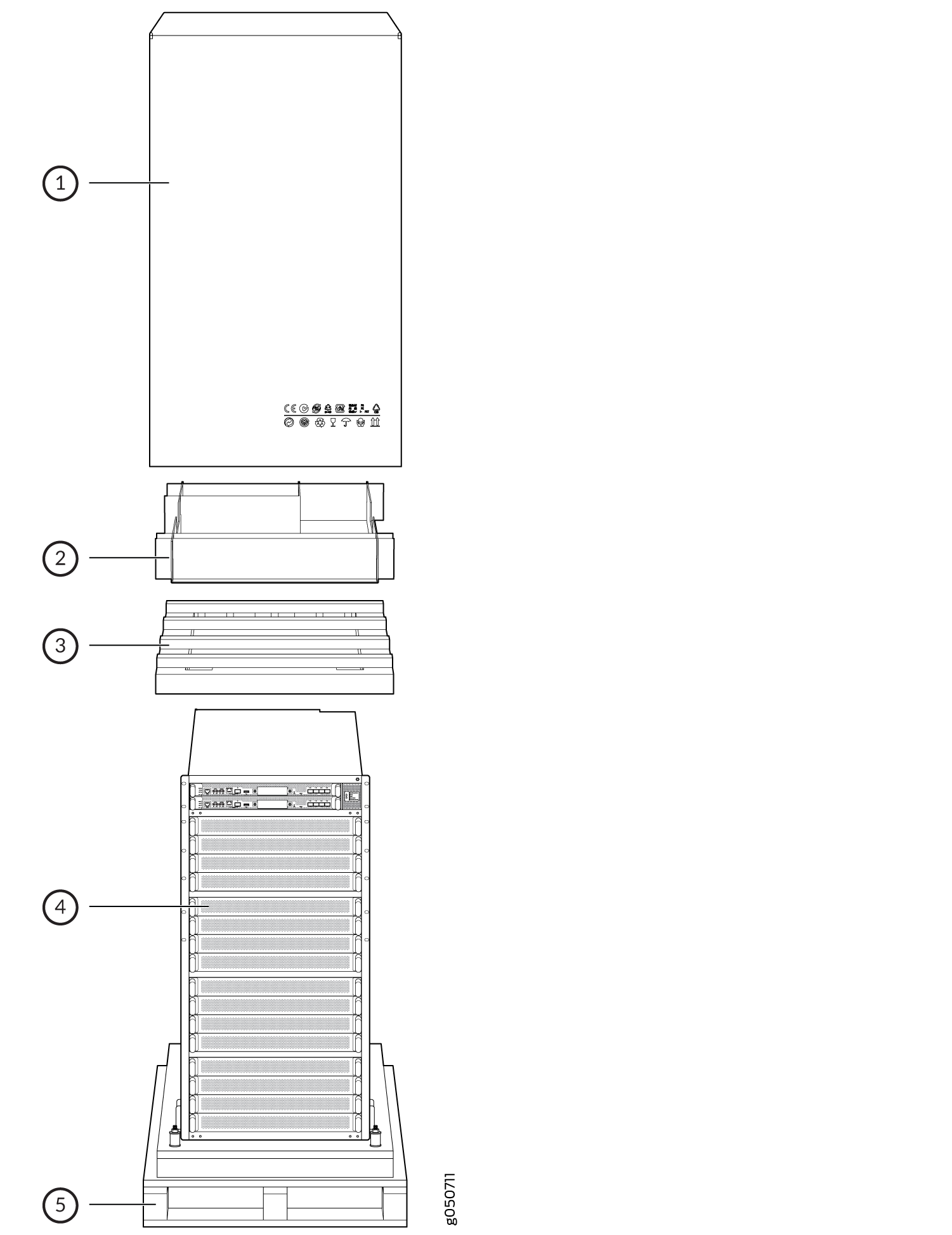
The chassis ships in a cardboard box that has a two-layer wooden pallet base with foam cushioning between the layers. The switch chassis is bolted to the pallet base.

The shipper has the option to either ship the front panel separately or to ship along with the chassis. If the front panel arrives with the chassis, set aside the front panel box until you are ready to verify the contents of the order.

To unpack the chassis (see Figure 1):

Figure 1: Shipping Crate and Accessory BoxShipping Crate and Accessory Box
  1. Move the shipping box to a staging area as close to the installation site as possible. While the chassis is bolted to the pallet, you can use a forklift or pallet jack to move it. Make sure there is enough space to remove components from the chassis.
  2. Position the shipping box with the arrows pointing up.
  3. Using the box cutter, slice the nylon straps that hold the shipping boxes to the pallet.
  4. Lift the shipping box off the chassis.
  5. Remove the cardboard accessory box.
  6. Remove the foam padding from the top of the box.
  7. Remove the plastic cover from the switch chassis.
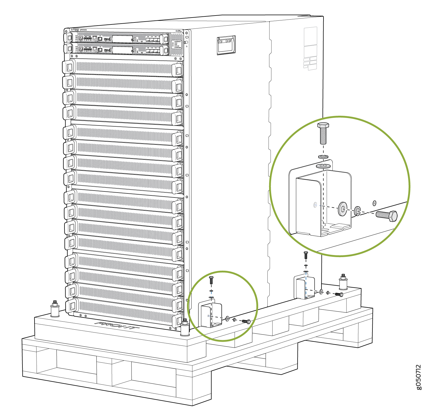
  8. Use a 13/32 in. (10 mm) open-end or socket wrench to remove the four sets of bracket bolts that secure the chassis to the shipping pallet (see Figure 2).
    Figure 2: Bracket Bolt RemovalBracket Bolt Removal
  9. Unpack the accessory box and lay out the contents so that they are ready for use.
  10. Verify that your order includes all appropriate parts. See Comparing the QFX10000 Order to the Packing List and QFX10016 Components and Configurations for information about base configurations and redundant configurations.
  11. Store the brackets and bolts inside the accessory box.
  12. Save the shipping box and packing materials in case you need to move or ship the switch at a later time.

Unpacking QFX10000 Line Cards, Routing and Control Boards, and Switch Interface Boards

Before you unpack a component:

Orders for line cards, additional Routing and Control Boards (RCBs), and Switch Interface Boards (SIBs) components are FRUs that are shipped separately from the switch chassis. The housing for the RCBs and line cards are rigid sheet-metal structures that house the electronics. SIBs have an exposed printed circuit board on one side and sheet metal on the other. All these components are shipped in a cardboard carton, secured with packing material.

CAUTION:

The components are maximally protected inside the shipping carton. Do not unpack them until you are ready to install the components in the switch chassis.

To unpack an RCB, SIB, or line card, (see Figure 3):

  1. Move the shipping carton to a staging area as close to the installation site as possible.
  2. Position the carton so that the arrows are pointing up.
  3. Open the top flaps on the shipping carton.
  4. Pull out the packing material that holds the component in place.
  5. Remove the component from the electrostatic bag.
  6. Save the shipping carton and packing materials for later, in case you need to move or ship the RCB, SIB, or line card.
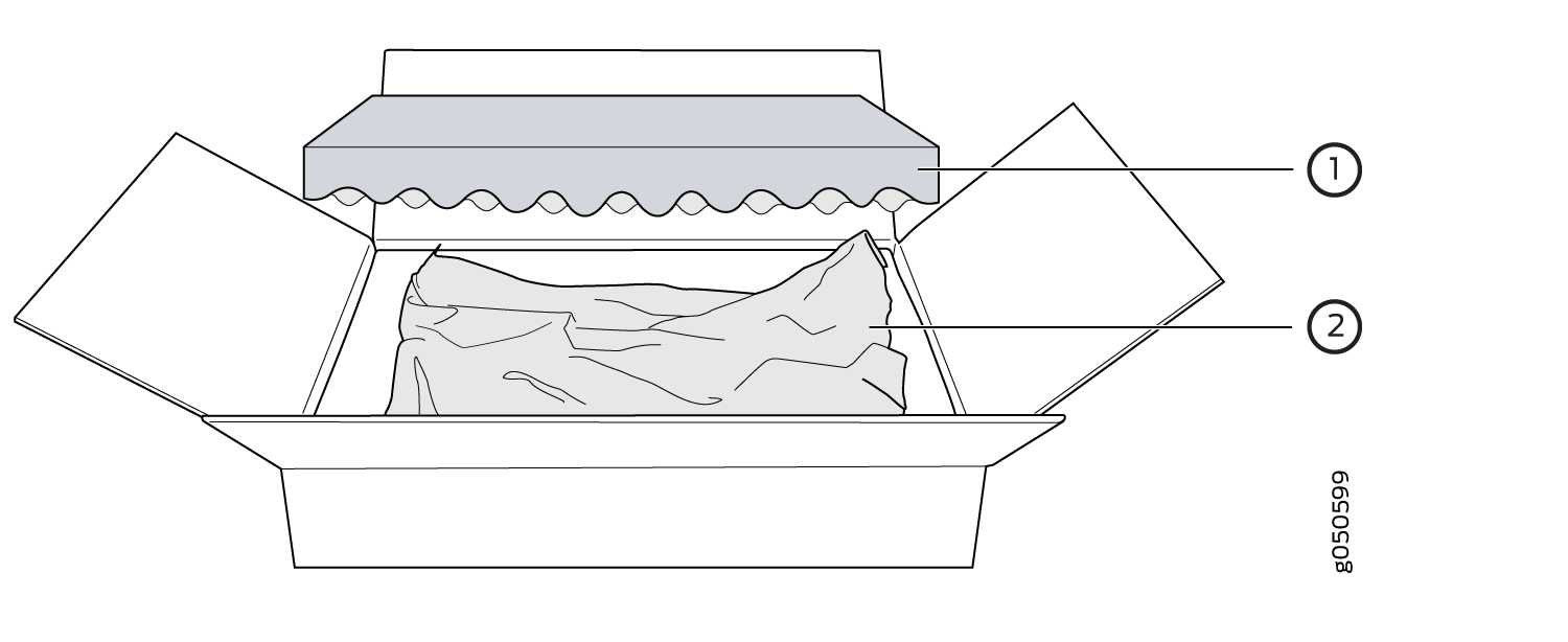
Figure 3: Unpacking a Line CardUnpacking a Line Card
  1

Foam packing material

  2

Paper packaging and electrostatic bag

Comparing the QFX10000 Order to the Packing List

Use the following procedure to compare the sales order and packing list against the contents of the chassis shipping crate.

The switch chassis shipment includes a packing list. Check the parts you receive in the shipping crate against the items on the packing list. The packing list specifies the part number and description of each part in your order.

If any part on the packing list is missing, contact your customer service representative, or contact Juniper Networks Customer Care from within the U.S. or Canada by telephone at 1-888-314-5822. For international-dial or direct-dial options in countries without toll-free numbers, see https://www.juniper.net/support/requesting-support.html.

Items that ship separately from the chassis are:

  • Line cards

  • Chassis front panel kit

    Note:

    The kit is a spare part and can ship with the chassis or separately.

  • Cable management kit

  • SATA solid state drive

  1. Determine the configuration. The parts shipped depend on the configuration you order. Supported configurations are:
    • Redundant configuration. See Table 1.

      • QFX10008-REDUND

      • QFX10008-REDUND-DC

      • QFX10008-REDUND-H

      • QFX10016-REDUND

      • QFX10016-REDUND-DC

    • Base configuration. See Table 2.

      • QFX10008-BASE

      • QFX10008-BASE-H

      • QFX10016-BASE

  2. Compare redundant configuration orders using Table 1.
    Table 1: Redundant Configuration Order

    Component

    QFX10008 Quantity

    QFX10016 Quantity

    Chassis, including power bus

    1

    1

    Routing Control Boards

    2

    2

    Fan tray controllers

    2

    2

    Fan trays

    2

    2

    Power supplies

    • QFX10000-PWR-AC

    • JNP10K-PWR-AC2

    • QFX10000-PWR-DC

    • JNP10K-PWR-DC2

    6

    10

    DC terminal lugs, 2-hole, 10-32, 4 AWG

    24 for DC systems only

    40 for DC systems only

    Power cables

    12 for AC systems; 0 for DC systems

    20 for AC systems; 0 for DC systems

    Switch Interface Boards (SIBs)

    6

    6

    Line card slot covers

    8

    16

    Accessory kit (see Table 3)

    1

    1

    Rack mount kit (see Table 4)

    1

    1

    Front panel kit (see Table 5)

    1

    1

    Documentation roadmap

    1

    1

    Port dust covers

    10

    10

  3. Compare base configuration orders using Table 2.
    Table 2: Base Configuration Order

    Component

    QFX10008 Quantity

    QFX10016 Quantity

    Chassis, including power bus

    1

    1

    Routing Control Boards

    1

    1

    Routing Control Board slot cover

    1

    1

    Fan tray controllers

    2

    2

    Fan trays

    2

    2

    Power supplies

    • QFX10000-PWR-AC

    • JNP10K-PWR-AC2

    • QFX10000-PWR-DC

    • JNP10K-PWR-DC2

    3

    5

    DC terminal lugs, 2-hole, 10-32, 4 AWG

    12, DC power supplies only

    20, DC power supplies only

    Power cables

    6, AC power supplies only

    10, AC power supplies only

    SIBs

    5

    5

    SIB slot cover

    1

    1

    Power supply slot cover

    3

    5

    Line card slot cover

    8

    16

    Accessory kit (see Table 3)

    1

    1

    Rack mount kit (see Table 4)

    1

    1

    Front panel kit (see Table 5)

    1

    1

    Documentation Roadmap

    1

    1

    Port dust covers

    5

    5

  4. Compare the contents of the accessory kit with Table 3.
    Table 3: QFX10000 Accessory Kit

    Component

    AC Configurations Quantity

    DC Configurations Quantity

    Warranty card

    1

    1

    End-user license agreement (EULA)

    1

    1

    Electrostatic discharge (ESD) wrist strap with cable

    1

    1

    Media kit (flash drives, PCMCIA card adapter)

    1

    1

    Chassis ground lug, 2-hole, 10-32, 6 AWG

    1

    1

    Power cord retainer clips

    • QFX10008

    • QFX10016

    • Redundant, 12

      Base, 6

    • Redundant, 20

      Base, 10

    ESD bags

    • 3 in. x 5 in.

    • 4 in. x 6 in.

    • 9 in. x 12 in.

    3

     
    Note:

    We no longer include a DB-9 to RJ-45 cable or a DB-9 to RJ-45 adapter with a CAT5E copper cable as part of the device package. If you require a console cable, you can order it separately with the part number JNP-CBL-RJ45-DB9 (DB-9 to RJ-45 adapter with a CAT5E copper cable).

  5. Compare the contents of the rack mount kit with Table 4.
    Table 4: QFX10000 Rack Mount Kit

    Component

    Quantity

    Phillips flat-head screws, 8-32 x .375 in.

    12

    Rear brackets

    2

    Right base bracket

    1

    Left base bracket

    1

  6. Compare the contents of the front panel kit with Table 5.
    Table 5: QFX10000 Front Panel Kit

    Component

    Quantity

    Front panel

    1

    Left base bracket

    1

    Right base bracket

    1

    Latch brackets

    2

    Phillips flat-head screws

    8

    Warranty card

    1

Register Products—Mandatory to Validate SLAs

Register all new Juniper Networks hardware products and changes to an existing installed product using the Juniper Networks website to activate your hardware replacement service-level agreements (SLAs).

CAUTION:

Register product serial numbers on the Juniper Networks website. Update the installation base data if any addition or change to the installation base occurs or if the installation base is moved. Juniper Networks is not responsible for not meeting the hardware replacement service-level agreement for products that do not have registered serial numbers or accurate installation base data.

Register your product(s) at https://tools.juniper.net/svcreg/SRegSerialNum.jsp.Update your installation base at https://www.juniper.net/customers/csc/management/updateinstallbase.jsp.