Maintaining QFX10000 Switch Interface Boards
Removing a QFX10000 Switch Interface Board
A QFX10008 and QFX10016 switch has six Switch Interface Boards (SIBs) that are located in the middle of the chassis behind the fan trays. SIB 0 through SIB 2 are located behind the left fan tray and SIB 3 through SIB 5 are located behind the right fan tray. You must remove the appropriate fan tray to access the failing SIB. See Removing a QFX10008 Fan Tray.
Ensure you have the following equipment on hand before replacing a SIB:
Electrostatic bag or antistatic mat
Electrostatic discharge (ESD) grounding strap
To remove a SIB (see Figure 4):
- Attach the ESD grounding strap to your bare wrist, and
connect the strap to the ESD point on the chassis. There is an ESD
point located next to the protective earthing terminal and below PSU 5 on the QFX10008 rear panel (see Figure 1) and below PSU_9 on the QFX10016 (see Figure 2.Figure 1: ESD Point on QFX10008 Chassis Rear
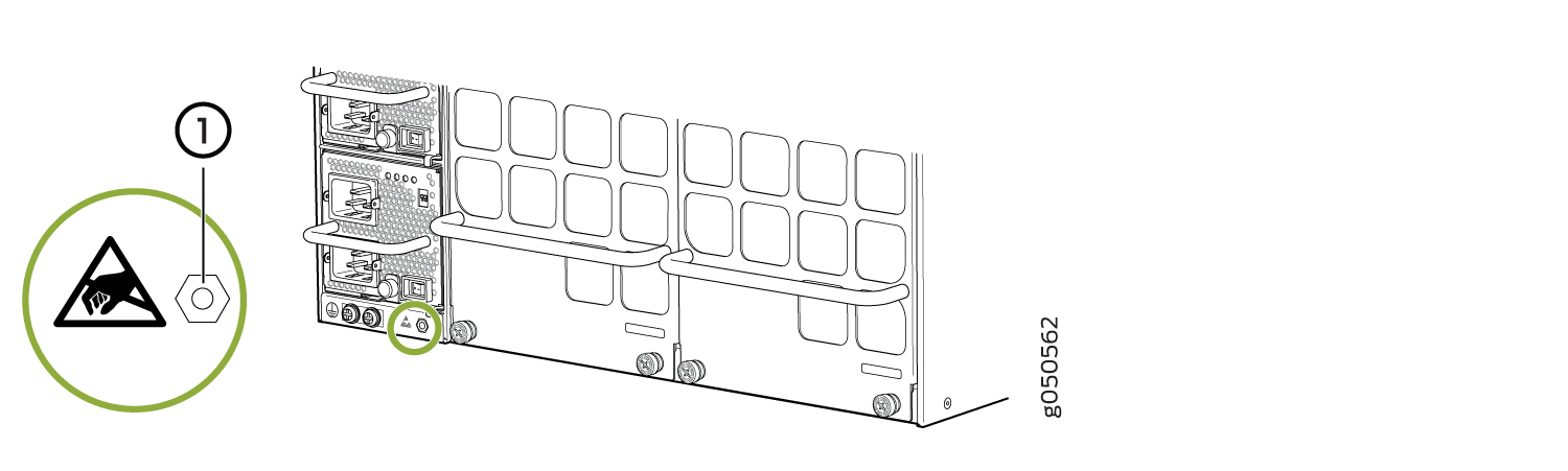 1—
1—ESD point
Figure 2: ESD Point on QFX10016 Chassis Rear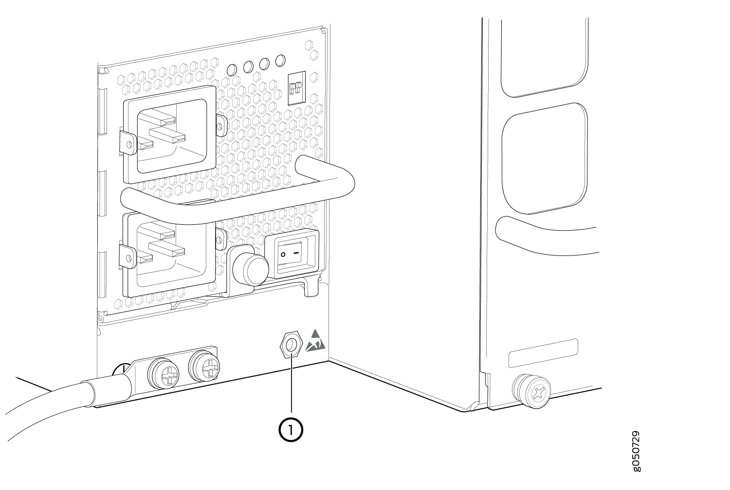
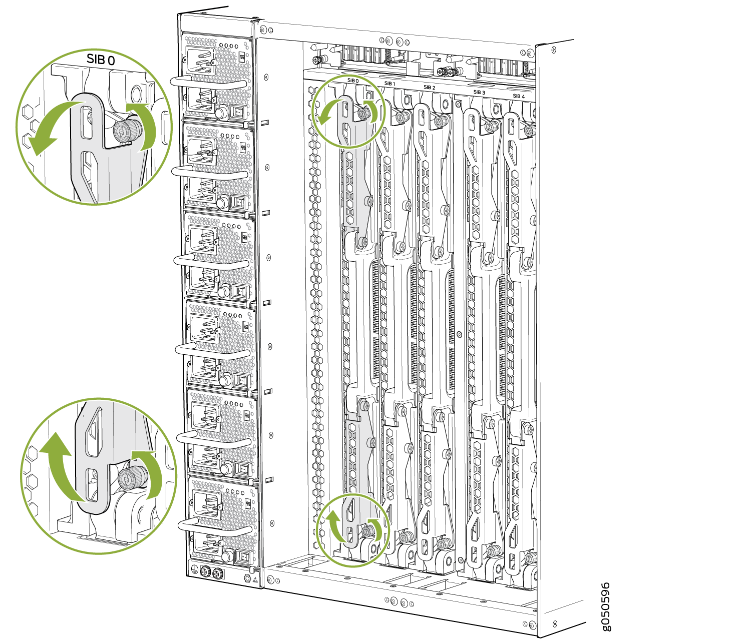
- Grasp both ejector handles and spread them apart. The
SIB slides about a quarter of the way out of the slot. See Figure 3.Figure 3: Loosening Captive Screws and Spread Ejector Handles
- Grasp the ejector handle with one hand and place your
other hand under the SIB for support as you slide the SIB out of the
slot (see Figure 4 and Figure 5).Figure 4: Removing the SIB from a QFX10008 Chassis
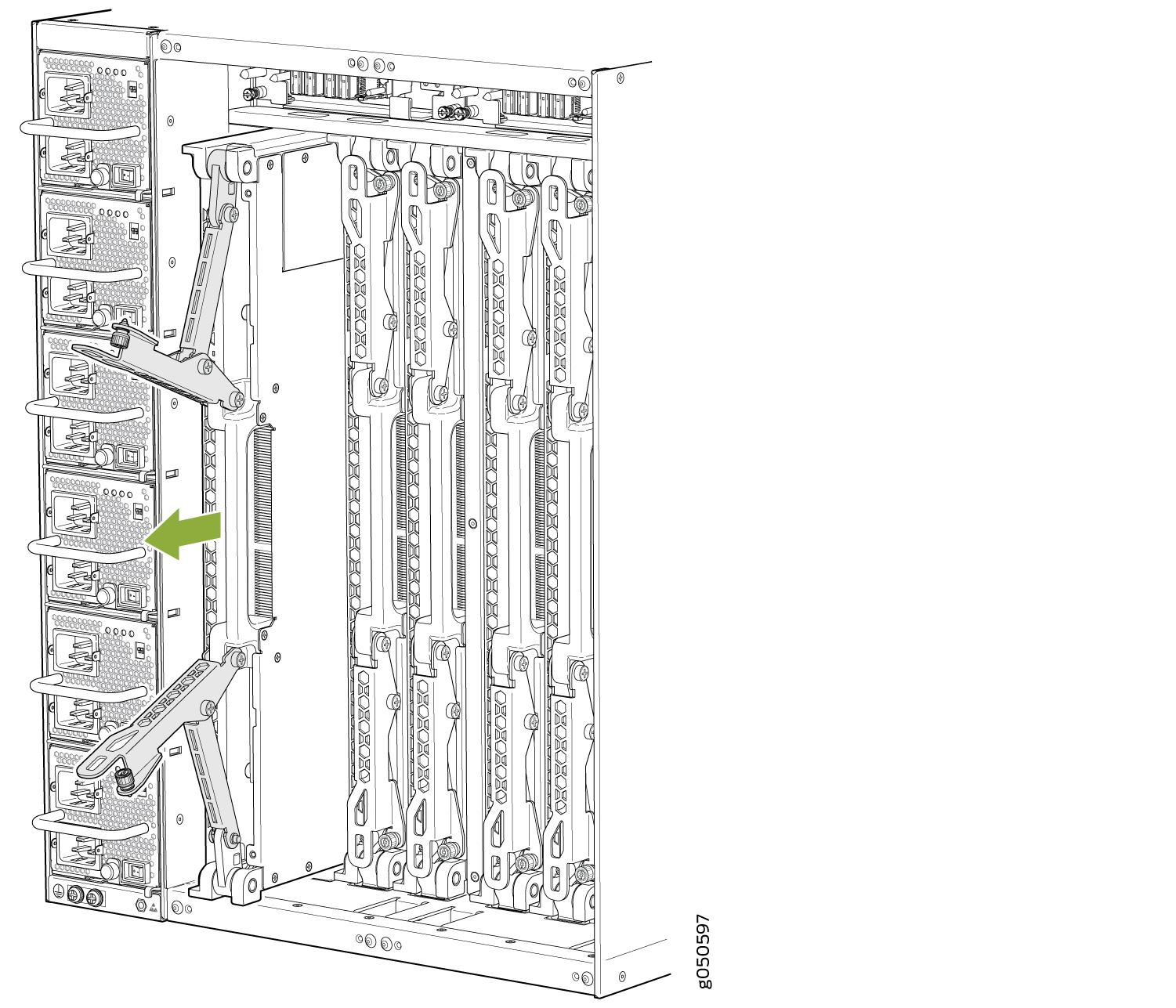 Figure 5: Removing the SIB from a QFX10016 Chassis
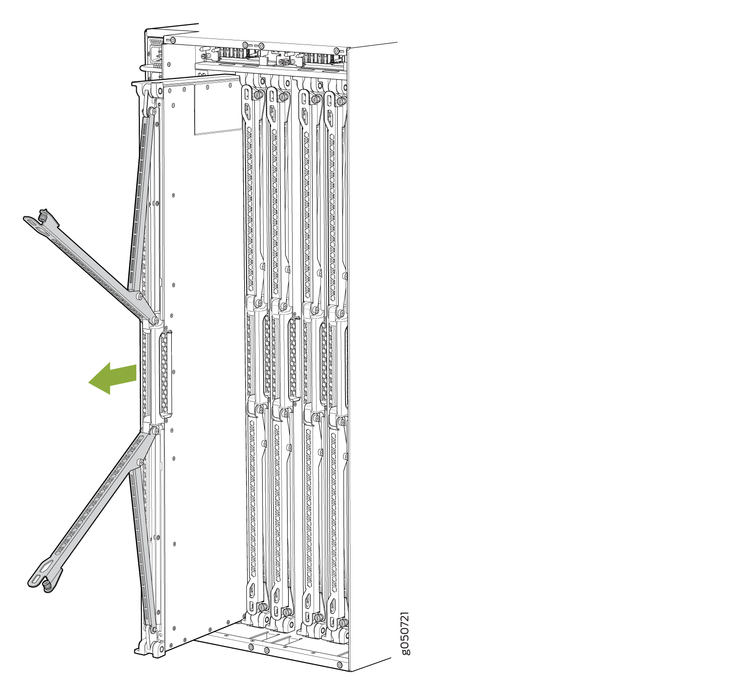
- Support the SIB as you rotate the SIB 90 degrees and place
it on the antistatic mat with the printed circuit (PC) board facing
upward. Be careful not to bump or handle the SIB by the connectors.
If you do not have an antistatic mat, have another person help you
slide the electrostatic bag over the SIB before placing it on the
stable surface. See Figure 6.CAUTION:
Do not stack hardware components on top of one another after you remove them. Place each component on an antistatic mat resting on a stable, flat surface.
Figure 6: Extracted SIB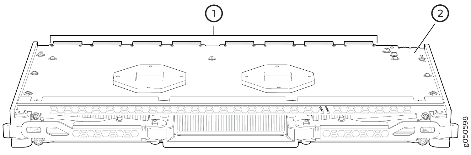 1—
1—Connectors
2—PC board
See Also
Installing a QFX10000 Switch Interface Board
A QFX10008 and QFX10016 switch has six Switch Interface Boards (SIBs) that are located in the middle of the chassis behind the fan trays. SIB 0 through SIB 2 are located behind the left fan tray, and SIB 3 through SIB 5 are located behind the right fan tray. You must remove the appropriate fan tray to install a SIB. See Removing a QFX10008 Fan Tray.
Ensure you have the following equipment on hand before installing a SIB:
Electrostatic bag or antistatic mat
Electrostatic discharge (ESD) grounding strap
To install a SIB:
- Attach the ESD grounding strap to your bare wrist, and
connect the strap to the ESD point on the chassis. There is an ESD
point located next to the protective earthing terminal and below PSU 5 on the QFX10008 rear panel (see Figure 7) and below PSU_9 on the QFX10016 rear panel (see Figure 8).Figure 7: ESD Point on QFX10008 Chassis Rear1—
ESD point
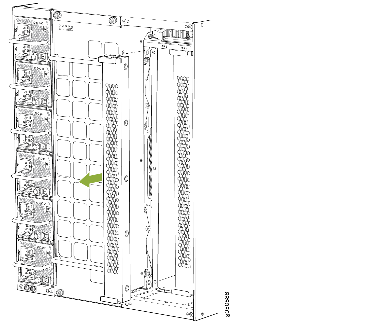
Figure 8: ESD Point on QFX10016 Chassis Rear - Either remove the failing SIB (see Removing a QFX10000
Switch Interface Board) or remove the cover by grasping
each side of the plate and pulling straight out (see Figure 9 for an example using the QFX10008).Figure 9: Removing a SIB Cover Plate on a QFX10008
- Grasp the two ejector handles and fold them inward until
they latch to seat the SIB (see Figure 10 for the QFX10008 and Figure 11 for the QFX10016).Figure 10: Installing a QFX10008 SIB
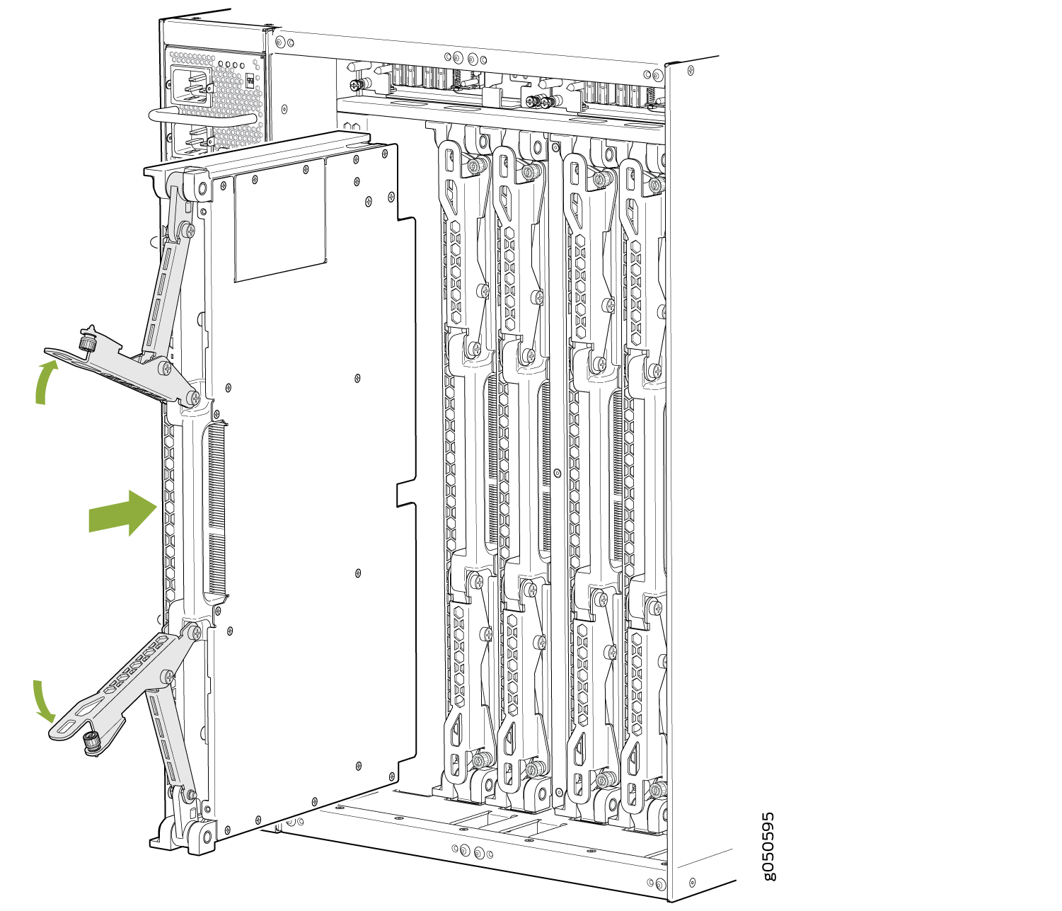 Figure 11: Installing a QFX10016 SIB