100-Gigabit DWDM OTN PIC with CFP2-ACO (PTX Series)
Software Release
PTX3000: Junos OS Release 15.1F6, Junos OS Release 17.1R1 and later
PTX5000: Junos OS Release 15.1F6, Junos OS Release 17.1R1 and later
For information about which FPCs support this PIC, see PTX Series PIC/FPC Compatibility.
Hardware Features
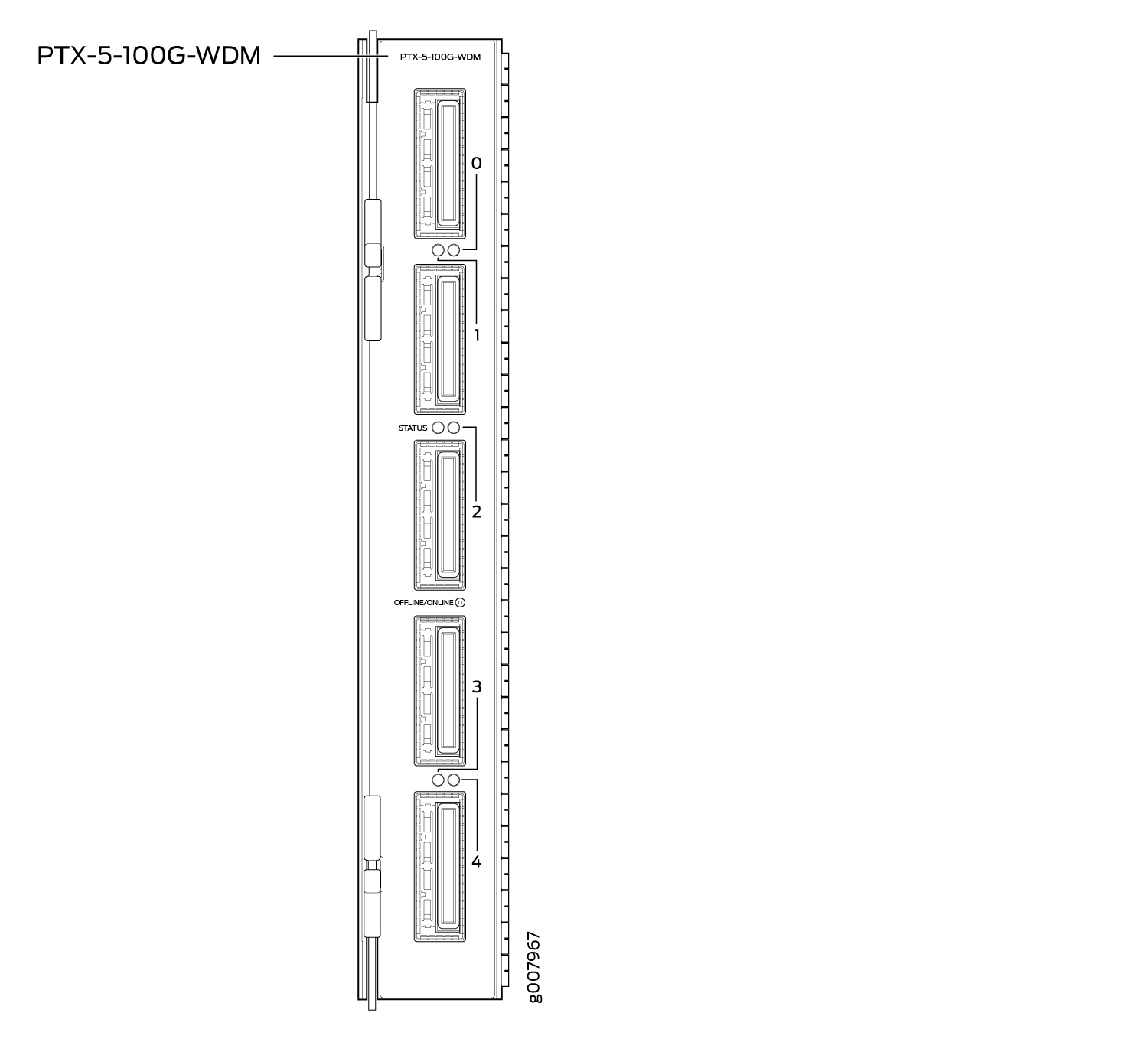
Model number: PTX-5-100G-WDM
Name in the CLI:
5X100GE DWDM CFP2-ACOFive 100-Gigabit DWDM OTN ports
Power requirement (including transceiver):
Typical: 4.15 A @ –48 V (199 W)
Maximum: 4.73 A @ –48 V (227 W)
Weight: 5.2 lb (2.4 kg)
Supports CFP2-ACO pluggable optics
Transparent transport of a 100-Gigabit Ethernet signal with OTU4V framing
ITU-standard OTN performance monitoring and alarm management
Dual polarization-quadrature phase-shift keying (DP-QPSK) modulation
Supports two types of forward error correction (FEC):
Soft-decision FEC (SD-FEC)
G.709 FEC (GFEC)
100 channels on C-band ITU grid with 50-GHz spacing
Latency:
SD-FEC: 14 µs (TX + RX)
GFEC: 6 µs (TX + RX)
Interoperable with the CFP-100GBASE-ZR transceiver supported on the 100-Gigabit Ethernet MIC with CFP (MIC3-3D-1X100GE-CFP) on MX Series routers and the 100-Gigabit Ethernet PIC with CFP (P1-PTX-2-100GE-CFP) on PTX Series routers.
Interoperable with the 100-Gigabit DWDM OTN MIC with CFP2 (MIC3-100G-DWDM) on MX Series routers when the 100-Gigabit DWDM OTN MIC is configured to use SD-FEC or GFEC.
The 5-port 100-Gigabit DWDM OTN PIC is not directly interoperable with the 2-port 100-Gigabit DWDM OTN PIC (P1-PTX-2-100G-WDM), but they can both operate over the same DWDM line system.
The 5-port 100-Gigabit DWDM OTN PIC is designed to comply with NEBS regulations on the PTX3000 and PTX5000 routers when these routers are used in typical configurations.
In a typical configuration, a PTX3000 router supports up to eight FPCs, with up to four 5-port 100-Gigabit DWDM OTN PICs installed next to any FPC. You can install other PICs next to any other FPC.
In a typical configuration, a PTX5000 router supports up to eight FPCs, with up to eight 5-port 100-Gigabit DWDM OTN PICs in any FPC slot. You can install other PICs in any FPC slot.
To comply with EMC regulations, you must also install front doors on the PTX3000 and PTX5000 chassis. See Installing the Front Doors on a PTX3000, Installing the Front Door on a PTX5000 in a Four-Post Rack, or Installing the Front Door on a PTX5000 in an Open-Frame Rack.
Software Features
Table 1 shows the first supported release for each software feature.
For information about configuring the PIC, see Configuring OTN Interfaces on PTX-5-100G-WDM PIC. For information about upgrading the firmware on the PIC, see Upgrading Firmware on the 5-Port 100-Gigabit DWDM OTN PIC (PTX-5-100G-WDM).
Software Feature |
PTX3000 First Supported Junos OS Release |
PTX5000 First Supported Junos OS Release |
|---|---|---|
Compliant with ITU G.709 and G.798 |
15.1F6 17.1R1 |
15.1F6 17.1R1 |
Provides a transport interface and state model (GR-1093) |
15.1F6 17.1R1 |
15.1F6 17.1R1 |
Performance monitoring features such as alarms, threshold-crossing alarms, OTU/ODU error seconds and pre-FEC statistics |
15.1F6 17.1R1 |
15.1F6 17.1R1 |
SNMP management of the PIC based on RFC 3591, Managed Objects for the Optical Interface Type, including the following:
|
15.1F6 17.1R1 |
15.1F6 17.1R1 |
IEEE 802.1ag OAM |
15.1F6 17.1R1 |
15.1F6 17.1R1 |
IEEE 802.3ah OAM |
15.1F6 17.1R1 |
15.1F6 17.1R1 |
Interface monitor (IFMON) and interface information (IFINFO) |
15.1F6 17.1R1 |
15.1F6 17.1R1 |
IEEE 802.3ad link aggregation |
15.1F6 17.1R1 |
15.1F6 17.1R1 |
Pre-FEC BER monitoring provides interrupt-driven BER-based detection of link signal degradation for MPLS fast reroute. |
15.1F6 17.1R1 |
15.1F6 17.1R1 |
User-configurable optics options:
|
15.1F6 17.1R1 |
15.1F6 17.1R1 |
User-configurable card options:
|
15.1F6 17.1R1 |
15.1F6 17.1R1 |
Cables and Connectors
You can use the Hardware Compatibility Tool to find information about the pluggable transceivers supported on your Juniper Networks device.
When inserting a C form-factor pluggable 2 (CFP2) transceiver, ensure that the transceiver sits tightly in the port. You hear a distinct click sound when the latch locks into the corresponding port. The latch must be fully engaged in the corresponding port for the CFP2 transceiver to function properly. Failing to do so can result in loss of connection.
To verify that the CFP2 transceiver module is inserted properly, give a gentle pull by grasping the sides of the module. The module should sit tightly.
The transceiver complies with the CFP Multi-Source Agreement (MSA) mechanical standard—transceiver weight does not exceed 210 g (7.41 oz).
LEDs
The STATUS LED is located in the center of the PIC faceplate adjacent to the link and activity LED for port 2. The link and activity LEDs are located between the ports and are numbered 0 through 4. Table 2 describes the functions of these LEDs.
Label |
Color |
State |
Description |
|---|---|---|---|
STATUS |
Green |
On steadily |
PIC is initialized and online with no alarms or failures. |
Red |
On steadily |
PIC is online but has errors or alarms. |
|
– |
Off |
PIC is offline or not enabled. |
|
Link and activity LED for each port |
Green |
On steadily |
Port is online with no alarms or failures, and the link is up. |
Blinking |
Activity is detected on the link. |
||
Red |
On steadily |
Port has detected a media alarm or failure. |
|
– |
Off |
Port is offline or not enabled. |
Alarms, Errors, and Events
For OTN alarms, see Table 3.
Chassis and PIC:
PIC (FRU) inserted or removed
PIC (FRU) Administrative State: In Service, Out Of Service
PIC (FRU) Operational State: Unequipped, Init, Normal, Mismatch, Fault, Upgrade
Mismatch equipment
Temperature alarm
Port (interface):
Interface Administrative State: In Service, Out Of Service, Service MA, Out of Service MA
Interface Operational State: Init, Normal, Fault, Degraded
Optical channel transport unit (OTU) TCAs:
OTU-TCA-BBE—15-minute background block error TCA
OTU-TCA-ES—15-minute far-end errored seconds TCA
OTU-TCA-SES—15-minute severely errored seconds TCA
OTU-TCA-UAS—15-minute unavailable seconds TCA
Optical channel data unit (ODU) TCAs:
ODU-TCA-BBE—15-minute background block error TCA
ODU-TCA-ES—15-minute far-end errored seconds TCA
ODU-TCA-SES—15-minute severely errored seconds TCA
ODU-TCA-UAS—15-minute unavailable seconds TCA
You can view OTU and ODU TCAs by using the show interfaces
transport pm otn operational-mode CLI command.
If you insert an invalid CFP module, the CLI displays unsupported
module and a syslog message is generated. You can verify whether
the CFP module is invalid by using the show chassis hardware operational-mode CLI command.
Optics-related status:
Module temperature
Module voltage
Module temperature alarm:
High alarm
Low alarm
High warning
Low warning
Module voltage alarm:
High alarm
Low alarm
High warning
Low warning
Module not ready alarm
Module low power alarm
Module initialization incomplete alarm
Module fault alarm
TX laser disabled alarm
RX loss of signal alarm
Modem lock state
TX output power:
Current TX output power
Minimum over PM interval
Maximum over PM interval
Average over PM interval
TX power alarm:
High alarm
Low alarm
High warning
Low warning
RX input power (signal)
RX input power (total):
Current RX input power (total)
Minimum over PM interval
Maximum over PM interval
Average over PM interval
RX power alarm:
High alarm
Low alarm
High warning
Low warning
RX loss of signal alarm
Wavelength unlocked alarm
You can view optics-related status by using the show interfaces
transport pm optics and show interfaces diagnostics optics operational-mode CLI commands.
Network lane receive-related status:
Chromatic dispersion:
Current chromatic dispersion
Minimum over PM interval
Maximum over PM interval
Average over PM interval
Differential group delay:
Current differential group delay
Minimum over PM interval
Maximum over PM interval
Average over PM interval
Q2-factor:
Current Q2-factor
Minimum over PM interval
Maximum over PM interval
Average over PM interval
Carrier frequency offset
Current carrier frequency offset
Minimum over PM interval
Maximum over PM interval
Average over PM interval
Signal-to-noise ratio (SNR)
Current SNR
Minimum over PM interval
Maximum over PM interval
Average over PM interval
You can view network lane receive-related status by using the show interfaces transport pm optics operational-mode CLI command.
FEC statistics:
Corrected Errors—the number of bits received that were in error, but corrected.
Uncorrected Words—the number of FEC codewords received that were uncorrectable.
Corrected Error Ratio—the number of corrected bits divided by the number of bits received
You can view FEC statistics by using the show interfaces interface-name extensive operational-mode CLI command.
Table 3 describes the OTN alarms and defects that can occur on the PIC and the link status when the alarm or defect occurs.
You can view OTN alarms and defects using the show interfaces interface-name extensive operational-mode CLI command.
Category |
Alarm |
Description |
Link Status |
|---|---|---|---|
OTN |
LOS |
Loss of signal |
Link down |
LOF |
Loss of frame |
Link down |
|
LOM |
Loss of multiframe |
Link down |
|
OTN FEC |
FEC Degrade (OTU-FEC-DEG) |
Forward error correction degraded |
Link down if signal degrade or backward FRR thresholds are met |
FEC Excessive (OTU-FEC-EXE) |
There are uncorrected words and there are errors in the frame header |
Possible link down |
|
OTN OTU |
OTU-AIS |
Alarm indication signal or all ones signal |
Link down |
OTU-BDI |
Backward defect identification |
Link down |
|
OTU-IAE |
Incoming alignment error |
Warning |
|
OTU-TTIM |
Destination access point identifier (DAPI), source access point identifier (SAPI), or both mismatch from expected to received |
Can cause the link to be down if |
|
OTU-BIAE |
Backward incoming alignment error |
Warning |
|
OTU-TSF |
OTU trail signal fail |
Warning |
|
OTU-SSF |
OTU server signal fail |
Warning |
|
OTN ODU |
ODU-AIS |
Alarm indication signal or all ones signal |
Link down |
ODU-OCI |
Open connection error |
Link down |
|
ODU-LCK |
ODU lock triggers for path monitoring and TCM levels 1 through 6 |
Link down |
|
ODU-BDI |
Backward defect indication |
Link down |
|
ODU-TTIM |
DAPI or SAPI mismatch from expected to received |
Can cause the link to be down if |
|
ODU-IAE |
Incoming alignment error |
Warning |
|
ODU-LTC |
Loss of tandem connection |
Warning |
|
ODU-CSF |
Client signal failure |
Warning |
|
ODU-TSF |
Trail signal fail |
Warning |
|
ODU-SSF |
Server signal fail |
Warning |
|
ODU-PTIM |
Payload type mismatch |
Link down |