Unpacking and Mounting the NFX150
Unpacking an NFX150 Device
The NFX150 devices are shipped in a cardboard carton, secured with foam packing material. The carton has an accessory compartment and contains the quick start instructions.
NFX150 devices are maximally protected inside the shipping carton. Do not unpack the devices until you are ready to begin installation.
To unpack the device:
- Open the carton.
- Pull out the packing material holding the device in place.
- Verify the parts received against the inventory on the label attached to the carton. See Parts Inventory (Packing List) for an NFX150 Device.
- Save the shipping carton and packing materials in case you need to move or ship the device later.
See Also
Parts Inventory (Packing List) for an NFX150 Device
The device shipment includes a packing list. Check the parts you receive in the device shipping carton against the items on the packing list. The parts shipped depend on the configuration you order.
If any part on the packing list is missing, contact your customer service representative or contact Juniper customer care from within the U.S. or Canada by telephone at 1-888-314-5822. For international-dial or direct-dial options in countries without toll-free numbers, see https://www.juniper.net/support/requesting-support.html.
Table 1 lists the parts and their quantities in the packing list.
|
Component |
Quantity |
|---|---|
|
Device |
1 |
|
AC power cord appropriate for your geographical location |
1 |
|
AC power cord retainer clip |
1 Note:
The AC power cord retainer clip is provided only with NFX150-S1 device. |
|
Mounting brackets |
2 |
|
Mounting screws to attach the mounting brackets to the device chassis |
8 |
|
Rubber feet |
4 |
|
Quick Start installation instructions |
1 |
|
Juniper Networks Product Warranty |
1 |
|
End User License Agreement |
1 |
We no longer include the console cable as part of the device package. If the console cable and adapter are not included in your device package, or if you need a different type of adapter, you can order the following separately:
-
RJ-45 to DB-9 adapter (JNP-CBL-RJ45-DB9)
-
RJ-45 to USB-A adapter (JNP-CBL-RJ45-USBA)
-
RJ-45 to USB-C adapter (JNP-CBL-RJ45-USBC)
If you want to use RJ-45 to USB-A or RJ-45 to USB-C adapter you must have X64 (64-Bit) Virtual COM port (VCP) driver installed on your PC. See, https://ftdichip.com/drivers/vcp-drivers/ to download the driver.
You must provide mounting screws that are appropriate for your rack or cabinet to mount the chassis on a rack or a cabinet.
See Also
Update Base Installation Data
Update the installation base data if any addition or change to the installation base occurs or if the installation base is moved. Juniper Networks is not responsible for not meeting the hardware replacement SLA for products that do not have accurate installation base data.
Update your installation base at https://supportportal.juniper.net/s/CreateCase .
Mounting an NFX150 Device
Table 2 lists the methods you can use to mount an NFX150 device.
Mounting Method |
Device Model |
Comments |
|---|---|---|
Desk or other level surface (using rubber feet) |
|
On a desk or other level surface by using rubber feet provided with the device. |
Two-post rack or cabinet |
|
On two posts in a rack or cabinet by using the mounting brackets. |
Four-post rack or cabinet |
|
On four posts in a rack or cabinet by using the mounting brackets. |
Wall mounting |
|
On a wall by using wall mounting brackets. |
The holes in the mounting brackets are placed at 1 U (1.75 in. or 4.45 cm) apart so that the device can be mounted in any rack or cabinet that provides holes spaced at that distance.
See the Related Documentation for detailed descriptions of the various rack or cabinet mounting options.
See Also
Mounting an NFX150 Device on a Desk or Other Level Surface
Before mounting the device on a desk or other level surface:
-
Verify that the site meets the requirements described in Site Preparation Checklist for NFX150 Devices.
-
Place the desk in its permanent location, allowing adequate clearance for airflow and maintenance, and secure it to the building structure.
-
Read General Safety Guidelines and Warnings, with particular attention to Chassis Lifting Guidelines for NFX150 Devices.
-
Ensure that you have the 4 rubber feet to stabilize the chassis on the a desk or other level surface (provided in the accessory box in the device carton)
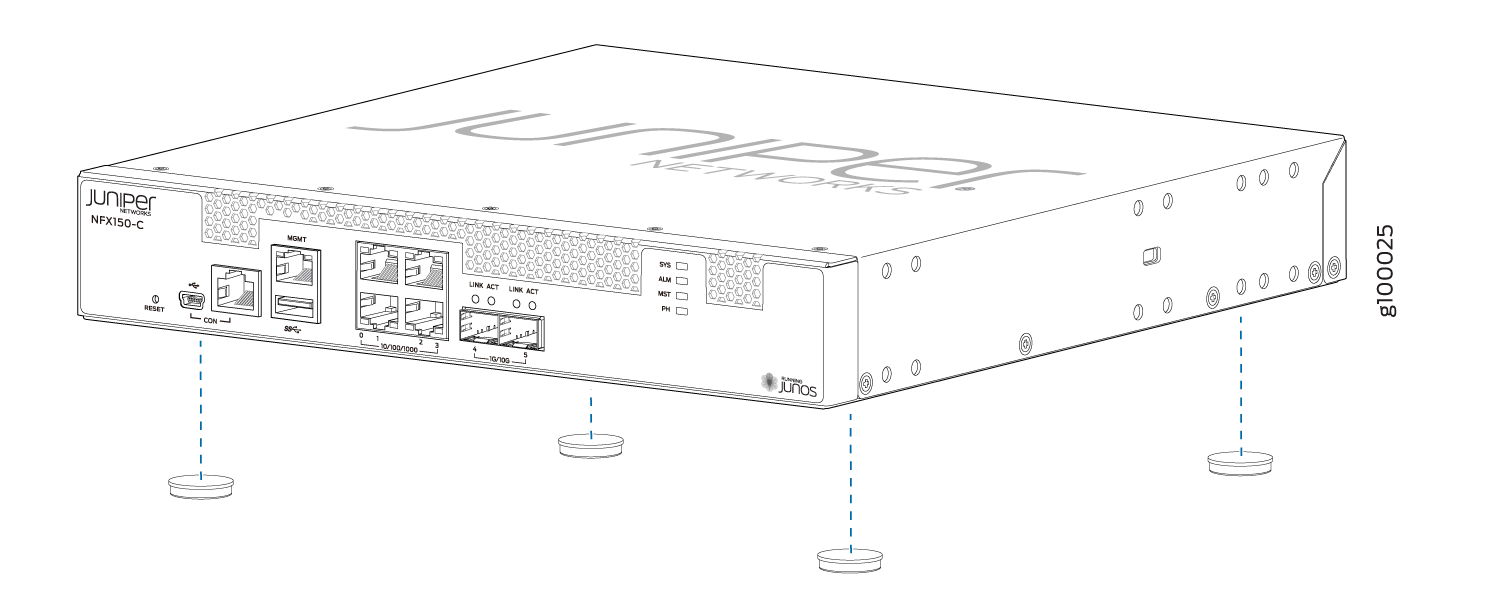
You can mount an NFX150-C-S1 device on a desk or other level surface by using the four rubber feet that are shipped with the device. The rubber feet stabilize the chassis.
To mount an NFX150-C-S1 device on a desk or other level surface:
-
Turn the chassis right side up on the desk or the level
surface.
Figure 1: Attaching Rubber Feet to the NFX150-C-S1 Device
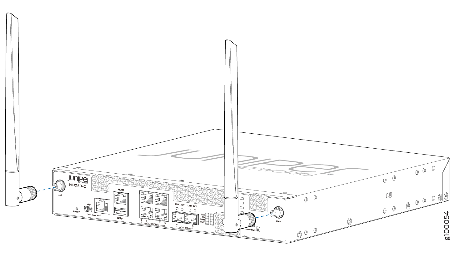
-
Attach the antennas to the antenna base of compact models
such as NFX150-C-S1-AA and NFX150-C-S1-AE with integrated LTE modem
support. See Figure 2.
Figure 2: Attaching Antennas to NFX150-C-S1-AA and NFX150-C-S1-AE
See Also
Mounting an NFX150 Device on a Wall
Before mounting an NFX150 device on a wall:
-
Verify that the site meets the requirements described in Site Preparation Checklist for NFX150 Devices.
-
Read General Safety Guidelines and Warnings, with particular attention to Chassis Lifting Guidelines for NFX150 Devices.
-
Remove the device from the shipping carton (see Unpacking an NFX150 Device).
Ensure that you have the following parts and tools available:
-
Phillips (+) screwdriver, number 2
-
2 wall-mount brackets (provided with the wall-mount kit)
-
8 wall-mount bracket screws (provided with the wall-mount kit)
-
4 mounting screws (8-32 x 1.25 in. or M4 x 30 mm) (not included)
-
Hollow wall anchors capable of supporting the weight of a fully loaded NFX150 device, up to 9 lb (4 kg) (not included)—if you are mounting the device in sheetrock (wall board with a gypsum plaster core) or in wall board not backed by wall studs
You can mount an NFX150 device on a wall by using the separately orderable wall-mount kit.
To mount the device on a wall:
-
Attach the wall-mount brackets to the sides of the chassis
using four of the wall-mount bracket screws on each side, as shown
in Figure 3 and Figure 4.
Figure 3: Attaching Wall-Mount Brackets to the NFX150 Device Chassis
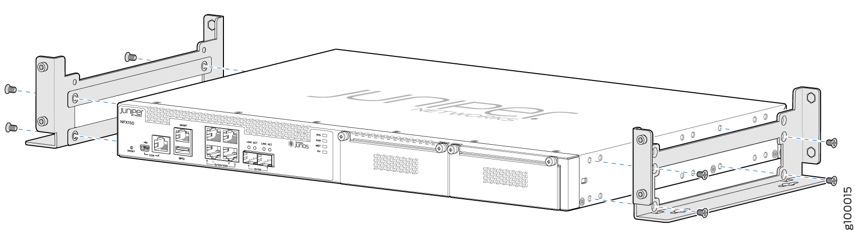 Figure 4: Attaching Wall-Mount Brackets to the NFX150-C-S1 Device Chassis
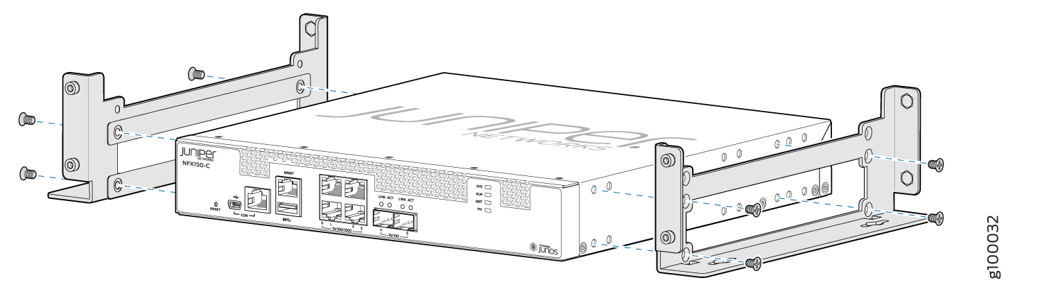
-
Install four mounting screws on the wall as shown in Figure 5 and Figure 6.
Figure 5: Measurements for Installing Mounting Screws for NFX150-S1 Device on a Wall
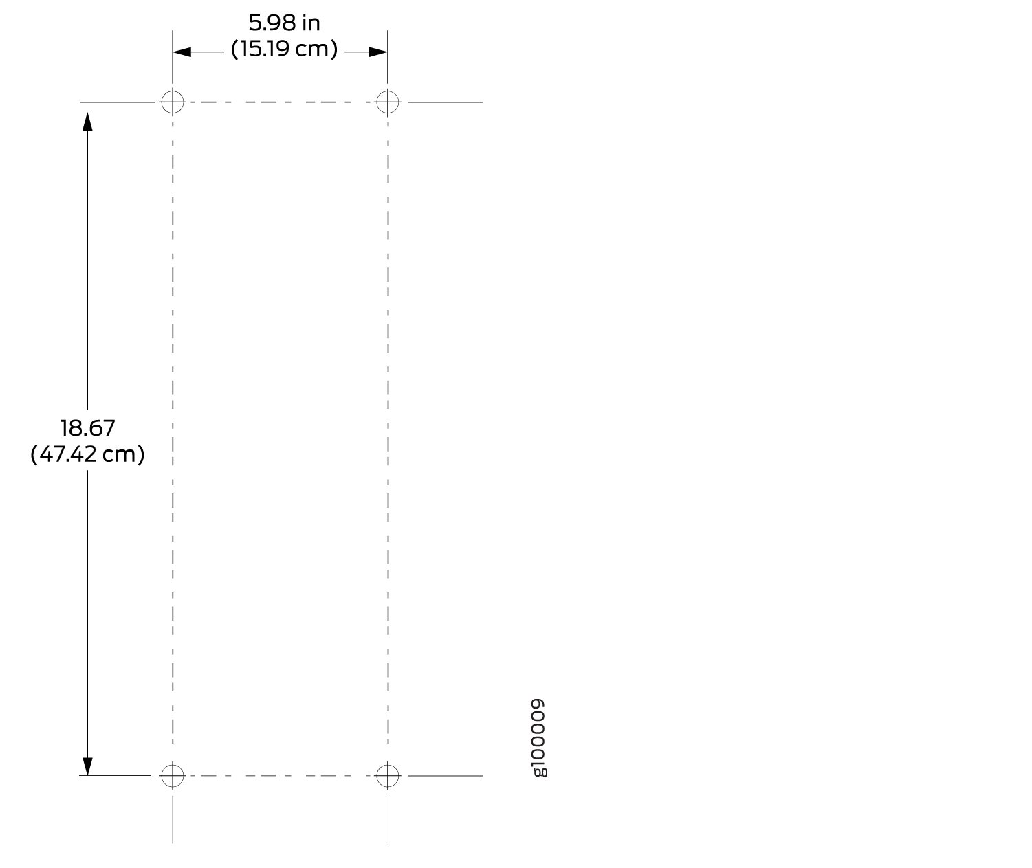 Figure 6: Measurements for Installing Mounting Screws for NFX150-C-S1 Device on a Wall
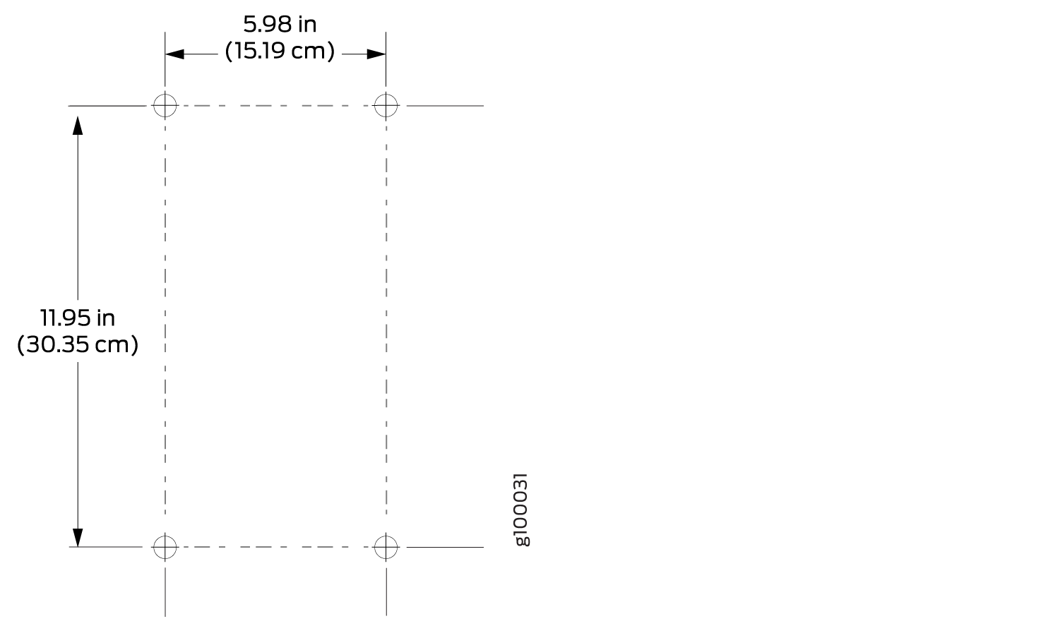
- Drill a hole A and install a mounting screw.
- Drill a hole B at a distance of 5.98 in. (15.19 cm.) on a level line to the right from hole A and install a mounting screw.
- Drill two holes at a distance of 18.67 in. (47.42 cm) on a plumb line from hole A and B, install the mounting screws.
- Screw the mounting screws only part way in, leaving about 1/4 in. (6 mm) distance between the head of the screw and the wall.
-
Grasp each side of the device, lift the device, and hang
the brackets from the mounting screws such that the front panel of
the device faces to your right or left side as shown in Figure 7 and Figure 8.
Figure 7: Mounting the NFX150-S1 Device on a Wall
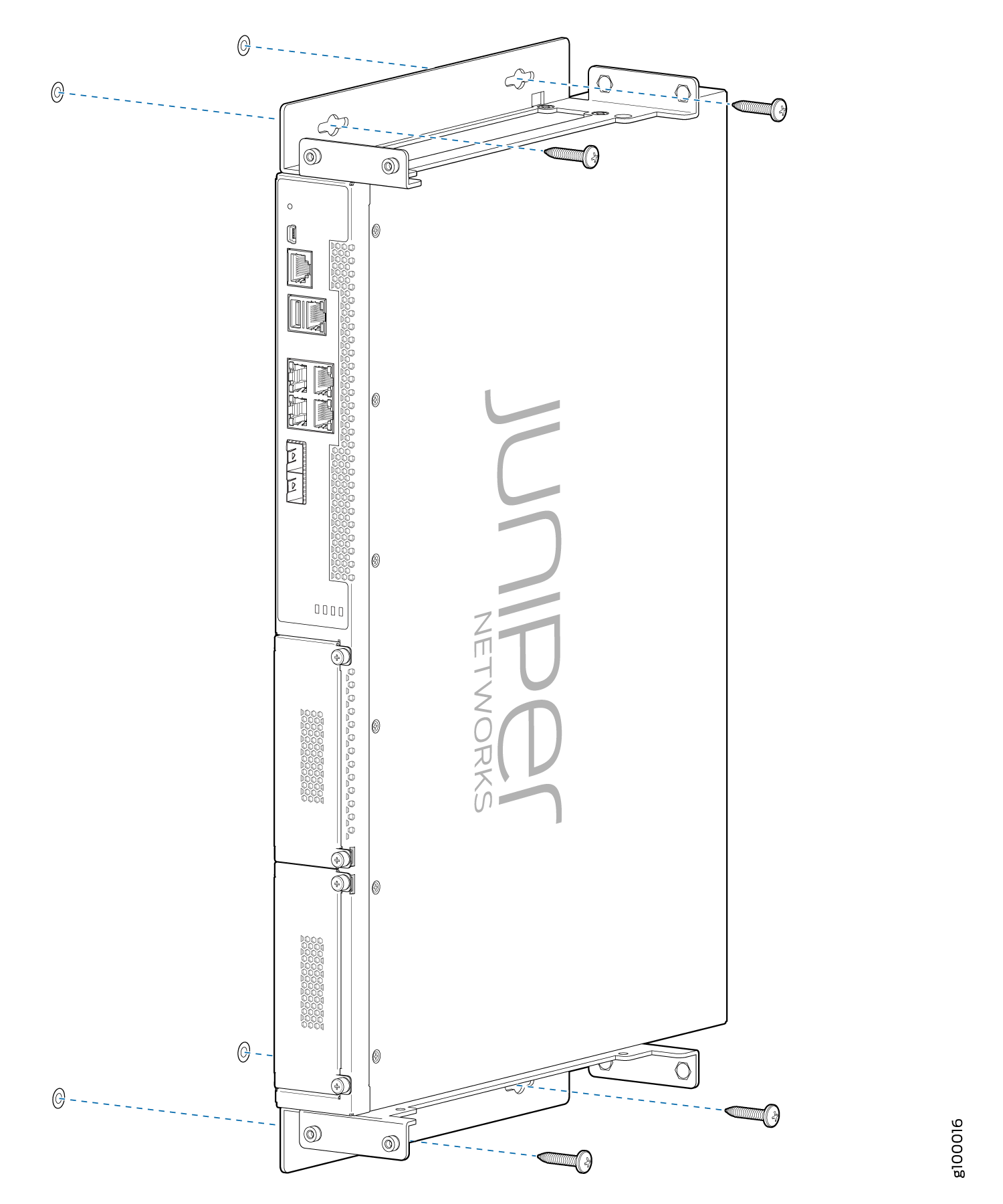 Figure 8: Mounting the NFX150-C-S1 Device on a Wall
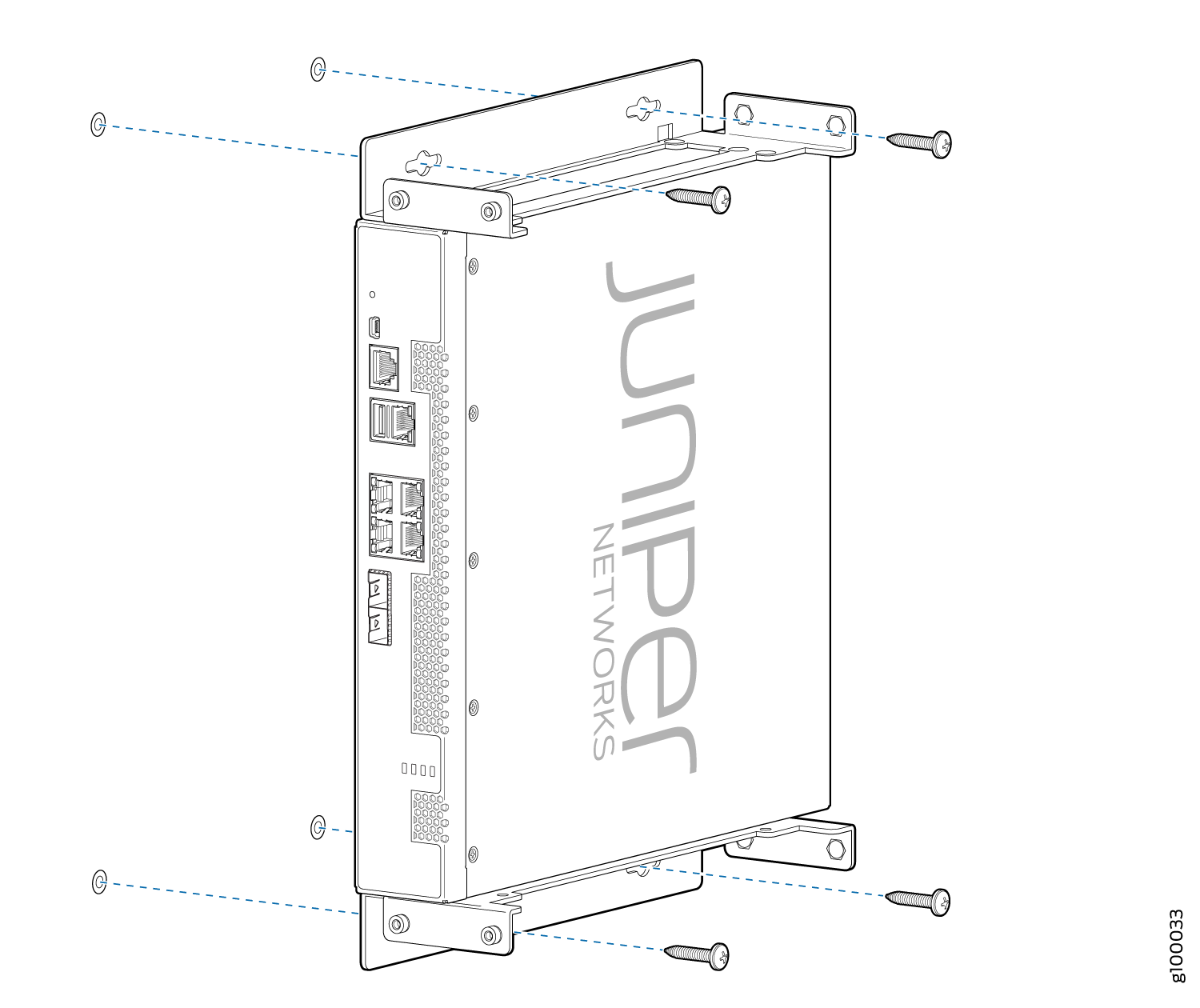
See Also
Mounting an NFX150 Device on Two Posts in a Rack
Before mounting an NFX150 device on two posts in a rack:
Place the rack in its permanent location, allowing adequate clearance for airflow and maintenance, and secure it to the building structure.
Remove the device from the shipping carton.
Ensure that you have the following parts and tools available:
Phillips (+) screwdriver, number 2
2 mounting brackets and 8 mounting screws (provided in the accessory box shipped with the device)
Screws to secure the chassis to the rack (not provided)
You can mount an NFX150 device on two posts of a 19-in. rack (either a two-post or a four-post rack).
If you need to mount the device in a recessed position on either a two-post rack or a four-post rack, you can use the 2-in.-recess front brackets provided in the separately orderable four-post rack-mount kit.
One person must be available to lift the device while another secures the device to the rack.
If you are mounting multiple devices on a rack, mount a device in the bottom of the rack first and proceed to mount the rest of the devices from bottom to top.
To mount the device on two posts in a rack:
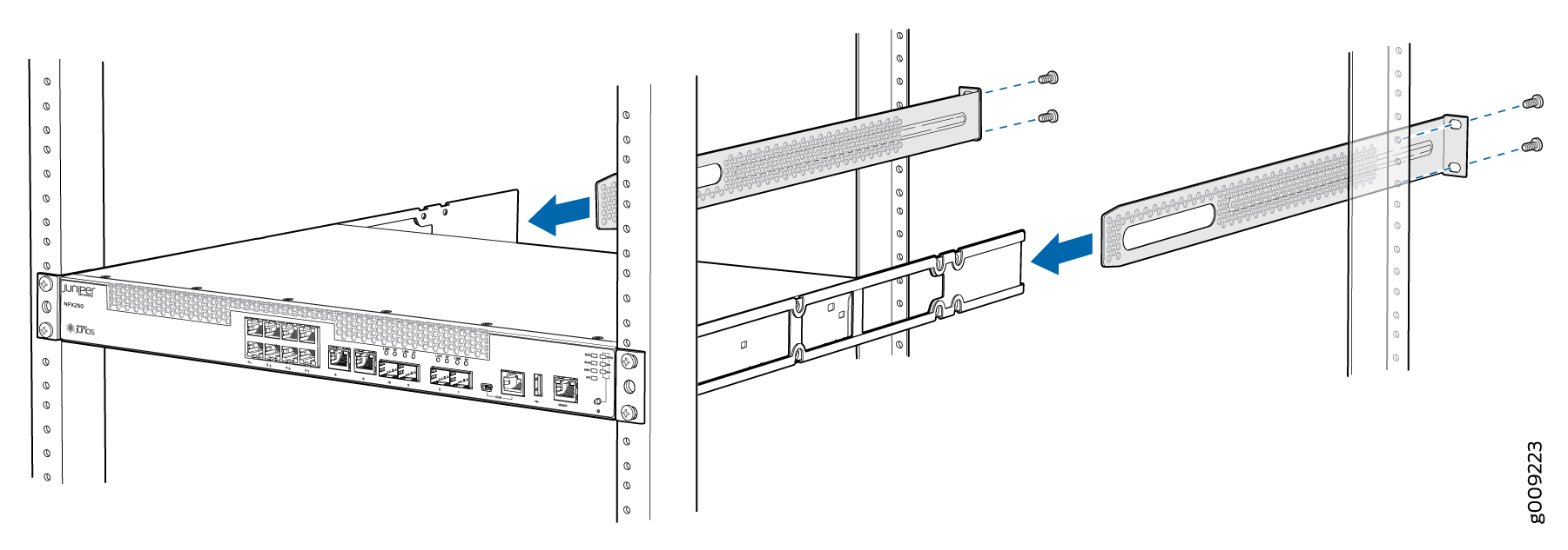
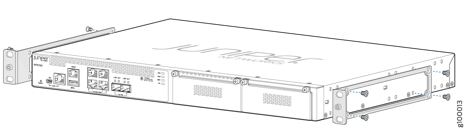
- Align the mounting brackets along the front, rear, or
center of the side panels of the device chassis depending on how you
want to mount the device. For example, if you want to front-mount
the device, align the brackets along the front of the side panel.
See Figure 9.Figure 9: Attaching the Mounting Bracket to the Side Panel of the Device
 Note:
Note:If you need to mount the device in a recessed position, use the 2-in.-recess front mount brackets from the separately orderable four-post rack-mount kit.
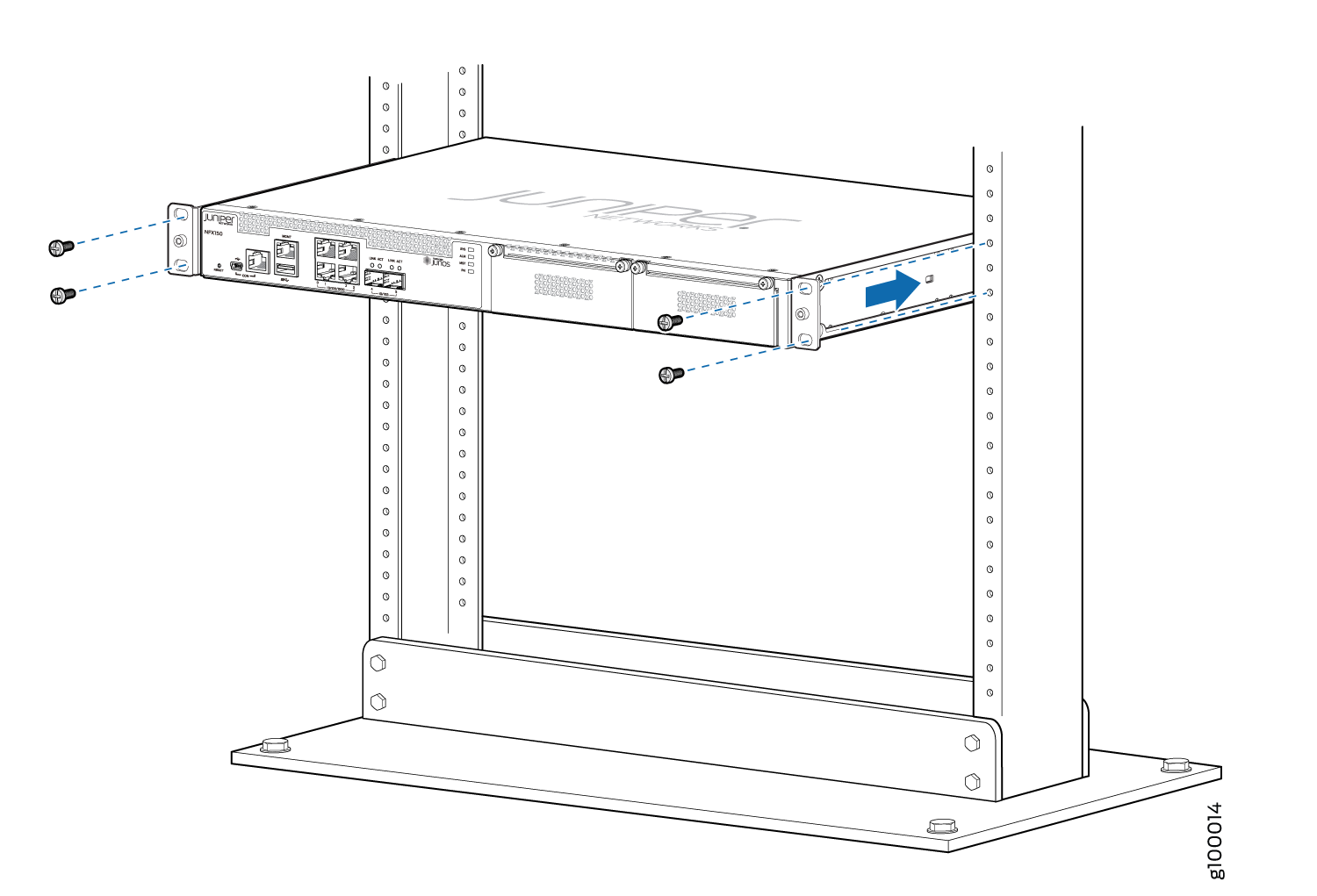
- Have one person grasp both sides of the device, lift the
device, and position it in the rack, aligning the mounting bracket
holes with the threaded holes in the rack or cabinet rail. Align the
bottom hole in both the mounting brackets with a hole in each rack
rail, making sure the chassis is level. See Figure 10.Figure 10: Mounting the Device on Two Posts in a Rack
See Also
Mounting an NFX150 Device on Four Posts in a Rack or Cabinet
Before mounting the device on four posts in a rack:
Place the rack in its permanent location, allowing adequate clearance for airflow and maintenance, and secure it to the building structure.
Read General Safety Guidelines and Warnings, with particular attention to Chassis Lifting Guidelines for NFX150 Devices.
Remove the device from the shipping carton (see Unpacking an NFX150 Device).
Have two persons available to mount the device. One person will support the device in a level position, and the second person will secure the device to the rack.
Ensure that you have the following parts and tools available:
Phillips (+) screwdriver, number 2
12 flat-head M4x6-mm Phillips mounting screws (provided with the four-post rack-mount kit)
One pair of front-mounting brackets
One pair of rear mounting-blades
Screws to secure the front-mounting brackets and the rear mounting-blades to the rack (not provided)
You can mount an NFX150 device on four posts of a 19-in. rack or cabinet by using the separately orderable four-post rack-mount kit. (The remainder of this topic uses rack to mean rack or cabinet.).
You can mount the device on two posts in either a two-post rack or a four-post rack by using the mounting brackets provided with the device. See Mounting an NFX150 Device on Two Posts in a Rack.
If you are mounting the device on four posts, ensure that the rack is 21.5 in. through 31.5 in. deep if you will mount the device flush with the rack front and that the rack is 23.5 in. through 32.5 in. deep if you will mount the device 2 in. recessed from the rack front, thus ensuring that the protective earthing terminal is accessible through the opening in the rear mounting-blade.
If you are mounting multiple units on a rack, mount the heaviest unit at the bottom of the rack and mount the other units from the bottom of the rack to the top in decreasing order of the weight of the units.
To mount the device on four posts in a rack:
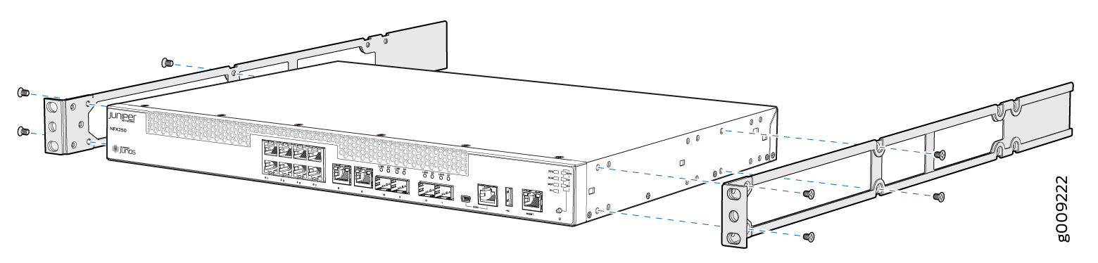
- Insert M4x6-mm Phillips flat-head mounting screws into
the two aligned holes and tighten the screws. Ensure that the remaining
two holes in the front bracket are aligned with the two holes in the
side panel. See Figure 11.Figure 11: Attaching the Front-Mounting Bracket to the Device Chassis
- Have one person grasp both sides of the device, lift the
device, and position it in the rack, aligning the front bracket holes
with the threaded holes in the front post of the rack. Align the bottom
hole in both the front-mounting brackets with a hole in each rack
rail, making sure the chassis is level. See Figure 12.Figure 12: Mounting the Device on the Front Posts in a Rack