Connecting the NFX150 to Power
Connecting Earth Ground to an NFX150 Device
. Electromagnetic Compatibility (EMC) and Electrostatic Discharge (ESD) requirements are met by the device chassis. The AC power cord provides surge protection.
You must install the NFX150 device in a restricted-access location and ensure that the chassis is always properly grounded. The NFX150 device has a two-hole protective grounding terminal provided on the chassis. See Figure 1 and Figure 2. We recommend that you use this protective grounding terminal as the preferred method for grounding the chassis regardless of the power supply configuration. However, if additional grounding methods are available, you can also use those methods. For example, you can use the grounding wire in the AC power cord or use the grounding terminal or lug on a DC power supply. This tested system meets or exceeds all applicable EMC regulatory requirements with the two-hole protective grounding terminal.
This topic describes:
- Parts and Tools Required for Connecting an NFX150 Device to Earth Ground
- Connecting Earth Ground to an NFX150 Device
Parts and Tools Required for Connecting an NFX150 Device to Earth Ground
Table 1 lists the earthing terminal location, grounding cable requirements, grounding lug specifications, screws and washers required, and the screwdriver needed for connecting a device to earth ground. Before you begin connecting a device to earth ground, ensure you have the parts and tools required for your device.
|
Device |
Earthing Terminal Location |
Grounding Cable Requirements |
Grounding Lug Specifications |
Screws and Washers |
Screwdriver |
|---|---|---|---|---|---|
|
NFX150-S1 |
Rear panel of chassis |
14 AWG (2 mm²), minimum 90°C wire, or as permitted by the local code |
Panduit LCC10-14BWL or equivalent—not provided |
|
Phillips (+) number 2 |
|
NFX150-C-S1 |
Rear panel of chassis |
14 AWG (2 mm²), minimum 90°C wire, or as permitted by the local code |
Panduit LCC10-14BWL or equivalent—not provided |
|
Phillips (+) number 2 |
Connecting Earth Ground to an NFX150 Device
To connect earth ground to a device:
-
Connect one end of the grounding cable to a proper earth ground, such as the rack in which the device is mounted.
-
Place the grounding lug attached to the grounding cable over the protective earthing terminal. See Figure 1 and Figure 2.
Figure 1: Connecting a Grounding Cable to an NFX150-S1 Device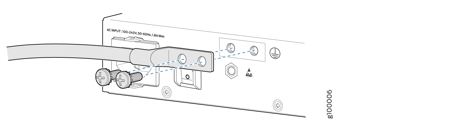 Figure 2: Connecting a Grounding Cable to an NFX150-C-S1 Device
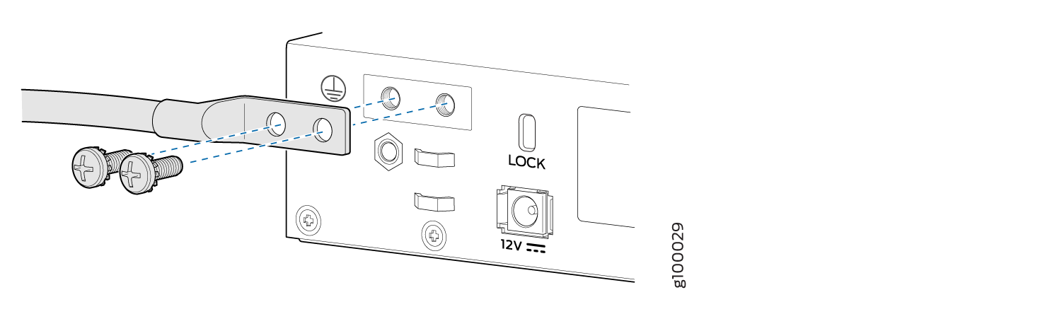
-
Secure the grounding lug to the protective earthing terminal with the washers and screws.
-
Dress the grounding cable and ensure that it does not touch or block access to other device components.
Warning:Ensure that the cable does not drape where people could trip over it.
Connecting AC Power to an NFX150 Device
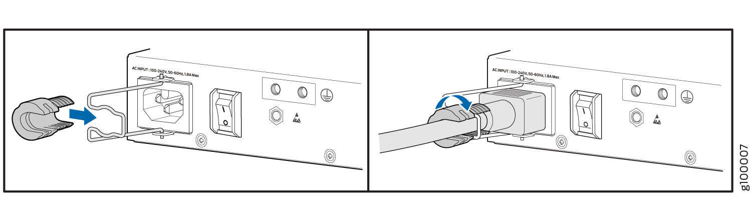
Ensure that you have the following parts and tools available:
A power cord appropriate for your geographical location
A power cord retainer clip
NFX150 device gets additional grounding when you plug the power supply in the device into a grounded AC power outlet by using the AC power cord appropriate for your geographical location (see AC Power Cord Specifications for an NFX150 Device).
The power supply in an NFX150 device is located on the rear panel.
To connect AC power to the device:
The retainer brackets on your device might be above and below the power inlet rather than on either side.