NFX150 Site Guidelines and Requirements
General Site Guidelines
Efficient device operation requires proper site planning. For the device to operate properly, you must ensure maintenance and proper layout of the equipment, rack or cabinet, and wiring closet.
To plan and create an acceptable operating environment for your device and prevent environmentally caused equipment failures:
Keep the area around the chassis free from dust and conductive material, such as metal flakes.
Follow the prescribed airflow guidelines to ensure that the cooling system functions properly. Ensure that the exhaust from other equipment does not blow into the intake vents of the device.
Follow the prescribed electrostatic discharge (ESD) prevention procedures to prevent damaging the equipment. Static discharge can cause components to fail completely or intermittently over time.
Install the device in a secure area, so that only authorized personnel can access the device.
Chassis Physical Specifications for an NFX150 Device
NFX150 device chassis is a rigid sheet-metal structure that houses the hardware components. Table 1 summarizes the physical specifications of the NFX150 chassis.
Product SKU |
Height |
Width |
Depth |
Weight |
|---|---|---|---|---|
NFX150-C-S1 |
1.72 in. (4.37 cm) |
10.66 in. (27.1 cm) |
11.17 in. (28.38 cm) |
8.6 lb (3.9 kg) |
NFX150-C-S1-AA |
1.72 in. (4.37 cm) |
10.66 in. (27.1 cm) |
11.17 in. (28.38 cm) |
8.6 lb (3.9 kg) |
NFX150-C-S1-AE |
1.72 in. (4.37 cm) |
10.66 in. (27.1 cm) |
11.17 in. (28.38 cm) |
8.6 lb (3.9 kg) |
NFX150-C-S1E-AA |
1.72 in. (4.37 cm) |
10.66 in. (27.1 cm) |
11.17 in. (28.38 cm) |
8.6 lb (3.9 kg) |
NFX150-C-S1E-AE |
1.72 in. (4.37 cm) |
10.66 in. (27.1 cm) |
11.17 in. (28.38 cm) |
8.6 lb (3.9 kg) |
NFX150-S1 |
1.72 in. (4.37 cm) |
17.36 in. (44.1 cm) |
12 in. (30.5 cm) |
11.68 lb (5.3 kg) |
NFX150-S1E |
1.72 in. (4.37 cm) |
17.36 in. (44.1 cm) |
15.50 in. (39.4 cm) |
11.68 lb (5.3 kg) |
Environmental Requirements and Specifications for an NFX150 Device
The device must be installed in a rack or cabinet. It must be housed in a dry, clean, well-ventilated, and temperature-controlled environment.
Follow these environmental guidelines:
The site must be as dust-free as possible, because dust can clog air intake vents and filters, reducing the efficiency of the device cooling system.
Maintain ambient airflow for normal operation of the device. If the airflow is blocked or restricted, or if the intake air is too warm, the device might overheat, leading to the device temperature monitor shutting down the device to protect the hardware components.
Table 2 provides the required environmental conditions for normal operation of the device.
Description |
Tolerance |
|---|---|
Altitude |
No performance degradation up to 6500 feet (1828 meters) at 96° F (40° C) |
Relative humidity |
Normal operation ensured in relative humidity range of 5% through 90%, noncondensing |
Temperature |
Normal operation ensured in temperature range of 32° F through 122° F (0° C through 40° C) |
Seismic |
Complies with Zone 4 earthquake requirements as per GR-63, Issue 4 |
See Also
Site Electrical Wiring Guidelines
Table 3 describes the factors you must consider while planning the electrical wiring at your site.
You must provide a properly grounded and shielded environment and use electrical surge-suppression devices.
Avertissement Vous devez établir un environnement protégé et convenablement mis à la terre et utiliser des dispositifs de parasurtension.
|
Site Wiring Factor |
Guidelines |
|---|---|
|
Signaling limitations |
If your site experiences any of the following problems, consult experts in electrical surge suppression and shielding:
|
|
Radio frequency interference |
To reduce or eliminate RFI from your site wiring, do the following:
|
|
Electromagnetic compatibility |
If your site is susceptible to problems with electromagnetic compatibility (EMC), particularly from lightning or radio transmitters, seek expert advice. Strong sources of electromagnetic interference (EMI) can cause:
|
Clearance Requirements for Airflow and Hardware Maintenance for an NFX150 Device
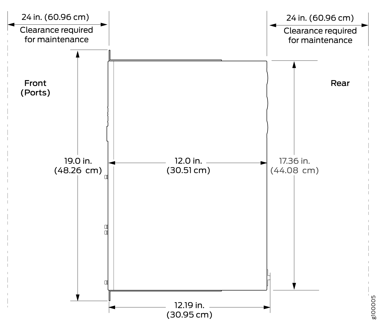
When planning the site for installing an NFX150 device, you must allow sufficient clearance around the installed chassis (see Figure 1 and Figure 2).
-
For the cooling system to function properly, the airflow around the chassis must be unrestricted. See NFX150 Cooling System for more information about the airflow through the chassis.
-
If you are mounting an NFX150 device in a rack or cabinet with other equipment, ensure that the exhaust from other equipment does not blow into the intake vents of the chassis.
-
Leave at least 24 in. (61 cm) both in front of and behind the NFX150 device. For service personnel to remove and install hardware components, you must leave adequate space at the front and back of the NFX150. NEBS GR-63 recommends that you allow at least 30 in. (76.2 cm) in front of the rack or cabinet and 24 in. (61 cm) behind the rack or cabinet.
See Also
Requirements for Mounting an NFX150 Device on a Desktop or Other Level Surface
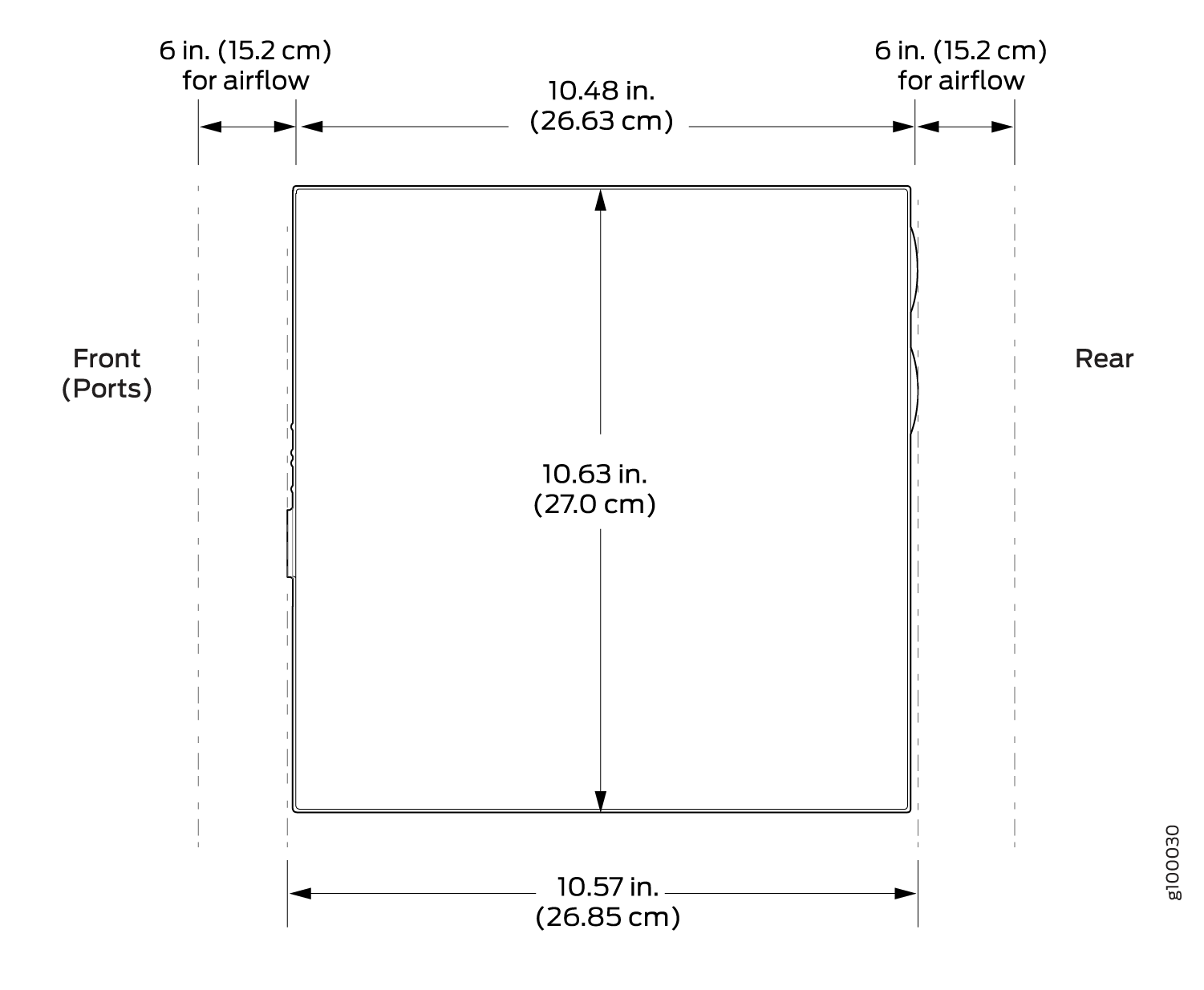
You can install NFX150 device on a desktop or other such level surface, by attaching the four rubber feet (provided) to the bottom of the chassis.
When choosing a location, allow at least 6 in. (15.2 cm) of clearance between the front and back of the chassis and adjacent equipment or walls.
Ensure that the desktop or other level surface on which the device is installed is stable and securely supported.
Requirements for Mounting an NFX150 Device on a Wall
You can install the NFX150 device on a wall. When choosing a location, allow at least 6 in. (15.2 cm) of clearance between the front and back of the chassis and adjacent equipment or walls.
Ensure that the wall onto which the device is installed is stable and securely supported.
If you are mounting the device in sheetrock (wall board with a gypsum plaster core) or in wall board not backed by wall studs, use hollow wall anchors capable of supporting the combined weight of two fully loaded chassis. Insert the screws into wall studs wherever possible to provide added support for the chassis.
Use the wall-mount kit from Juniper Networks to mount the device on a wall. The wall-mount kit is not part of the standard package and must be ordered separately.
Rack Requirements for NFX150 Devices
You can mount the NFX150 devices on two-post racks or four-post racks.
Rack requirements consist of:
Rack type
Mounting bracket hole spacing
Rack size and strength
Rack connection to the building structure
Table 4 provides the rack requirements and specifications for the device.
Rack Requirement |
Guidelines |
|---|---|
Rack type |
Use a two-post rack or a four-post rack. You can mount the device on any two-post or four-post rack that provides bracket holes or hole patterns spaced at 1 U (1.75 in. or 4.45 cm) increments and that meets the size and strength requirements to support the weight. A U is the standard rack unit defined by the Electronic Components Industry Association (https://www.ecianow.org). The rack must meet the strength requirements to support the weight of the chassis. |
Mounting bracket hole spacing |
The holes in the mounting brackets are spaced at 1 U (1.75 in. or 4.45 cm), so that the device can be mounted in any rack that provides holes spaced at that distance. |
Rack size and strength |
|
Rack connection to building structure |
|
One pair of mounting brackets for mounting the device on two posts of a rack is supplied with each device. For mounting the device on four posts of a rack or cabinet, you can order a four-post rack-mount kit separately.
See Also
Cabinet Requirements for an NFX150 Device
You can mount the NFX150 device in an enclosure or cabinet that contains a four-post 19-in. open rack as defined in Cabinets, Racks, Panels, and Associated Equipment (document number EIA-310-D) published by the Electronics Industry Association.
Cabinet requirements consist of:
Cabinet size and clearance
Cabinet airflow requirements
Table 5 provides the cabinet requirements and specifications for the NFX150 device.
Cabinet Requirement |
Guidelines |
|---|---|
Cabinet size and clearance |
The minimum cabinet size for accommodating an NFX150 device is 36 in. (91.4 cm) deep. Large cabinets improve airflow and reduce the chance of overheating. |
Cabinet airflow requirements |
When you mount the NFX150 device in a cabinet, ensure that ventilation through the cabinet is sufficient to prevent overheating.
|