NFX150 Chassis
Front Panel of an NFX150 Device
Figure 1 shows the front panel components of an NFX150-C-S1 device.
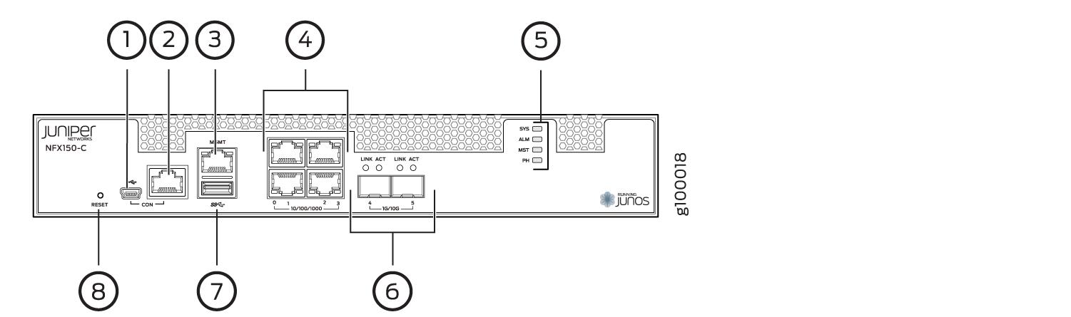
1 — Mini-USB console port | 5 — System status LEDs |
2 — RJ-45 console port | 6 — Two 1-Gigabit Ethernet/10-Gigabit Ethernet SFP+ WAN ports |
3 — One 10/100/ 1000BASE-T RJ-45 management port | 7 — USB 3.0 port |
4 — Four 10/100/ 1000BASE-T RJ-45 LAN ports | 8 — Reset button |
Figure 2 shows the front panel components of NFX150-C-S1-AA and NFX150-C-S1-AE devices.
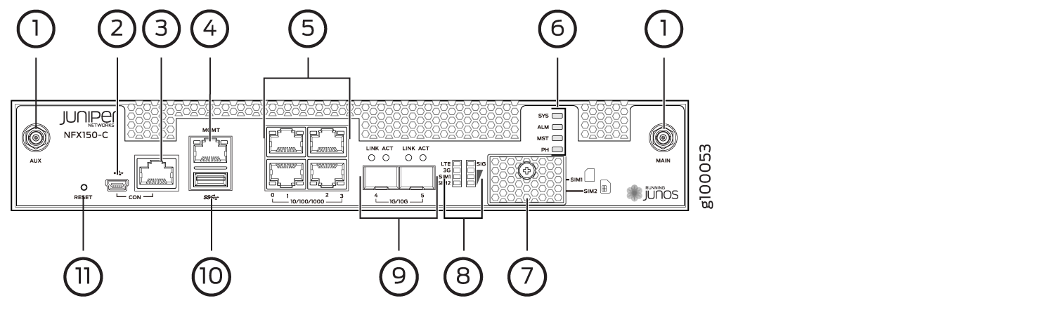
1 — Antenna slot | 7 — SIM card cover |
2 — Mini USB console port | 8 — LTE modem LEDs |
3 — RJ-45 console port | 9 — Two 1-Gigabit Ethernet/10-Gigabit Ethernet SFP+ WAN ports |
4 — One 10/100/1000BASE-T RJ-45 management port | 10 — USB 3.0 port |
5 — Four 10/100/1000BASE-T RJ-45 LAN ports | 11 — Reset button |
6 — System status LEDs |
Figure 3 shows the front panel components of an NFX150-S1 device.
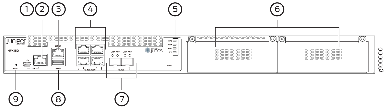
1 — Mini USB console Port | 6 — Expansion module slots |
2 — RJ-45 console port | 7 — Two 1-Gigabit Ethernet/10-Gigabit Ethernet SFP+ WAN ports |
3 — One 10/100/1000BASE-T RJ-45 management port | 8 — USB 3.0 port |
4 — Four 10/100/1000BASE-T RJ-45 LAN ports | 9 — Reset button |
5 — System status LEDs |
Rear Panel of an NFX150 Device
Figure 4 shows the rear panel of the NFX150-C-S1 device. The rear panel of the NFX150-C-S1 device consists of the following components:
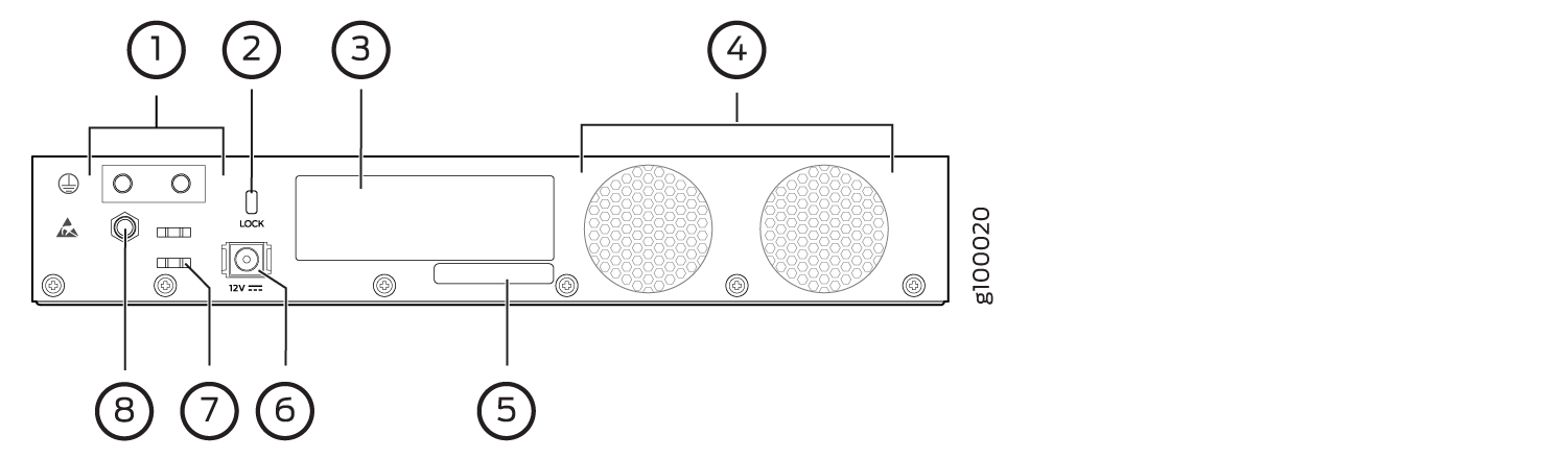
1 — Grounding point | 5 — CLEI code |
2 — Lock | 6 — Power supply input |
3 — Serial number | 7 — Cable tie holder |
4 — Fans | 8 — Electrostatic discharge (ESD) point |
Figure 5 shows the rear panel of the NFX150-S1 device. The rear panel of the NFX150-S1 device consists of the following components:
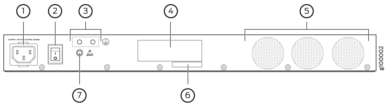
1 — AC power cord inlet | 5 — Fans |
2 — Power switch | 6 — CLEI code |
3 — Grounding point | 7 — Electrostatic discharge (ESD) point |
4 — Serial number |
LED Details of an NFX150 Device
Chassis Status LEDs
The front panel of an NFX150-C-S1 and NFX150-S1 devices have chassis status LEDs labeled ALM, SYS, MST and PH.
Figure 6 shows the chassis status LEDs in an NFX150-C-S1 device.
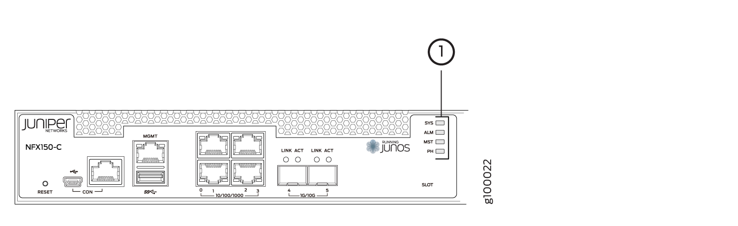
1 — Chassis status LEDs (ALM, SYS, MST, and PH) |
Figure 7 shows the chassis status LEDs in an NFX150-S1 device.
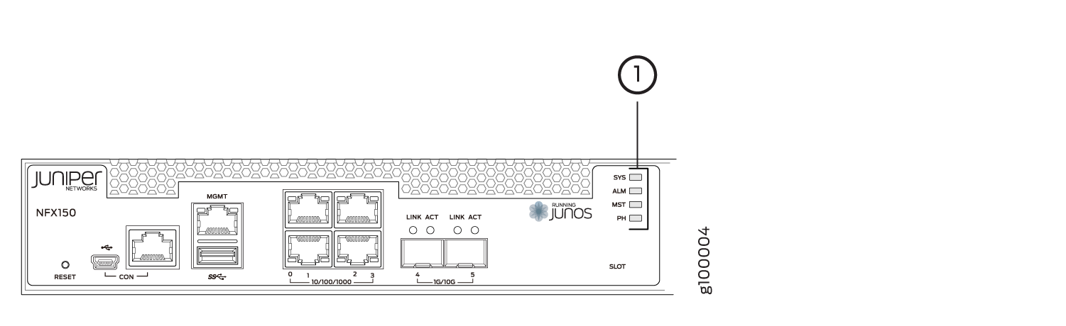
1 — Chassis status LEDs (ALM, SYS, MST, and PH) | 2 — Slot |
Table 1 describes
the chassis status LEDs in an NFX150 device, their colors and states,
and the status they indicate. You can view the colors of the four
LEDs remotely through the CLI by issuing the operational mode command show chassis led.
|
LED Label |
Color |
State and Description |
|---|---|---|
|
ALM (Alarm) |
Unlit |
There is no alarm or the device is halted. |
|
Red |
There is a major alarm. |
|
|
Amber |
There is a minor alarm. |
|
|
SYS (System) |
Green |
|
|
MST (Primary) |
Green |
|
|
PH |
Unlit |
There is no Network Service Activator transaction. |
|
Green |
|
|
|
Amber |
|
A major alarm (red) indicates a critical error condition that requires immediate action.
A minor alarm (amber) indicates a noncritical condition that requires monitoring or maintenance. A minor alarm left unchecked might cause interruption in service or performance degradation.
All four LEDs can be lit simultaneously.
Network Port and Uplink Port LEDs
Each network port and uplink port on the front panel of an NFX150 has two LEDs that indicate link activity and port status (see Figure 8).
Table 2 describes the Link/Activity LED.
|
LED |
Color |
State and Description |
|---|---|---|
|
Link/Activity |
Green |
|
Management Port LEDs
The management port on the front panel of an NFX150 device has two LEDs that indicate link activity and port status.
Table 3 describes the Link/Activity LED.
|
LED |
Color |
State and Description |
|---|---|---|
|
Link/Activity |
Green |
|
Table 4 describes the status LED.
|
LED |
Color |
State and Description |
|---|---|---|
|
Status |
Green |
Indicates the speed. The speed indicators are:
|
Table 5 describes the slot LED.
|
LED |
Color |
State and Description |
|---|---|---|
|
Slot |
Green solid (On) |
Module initial process is successful. |
|
Amber solid |
Module initial process failed |
|
|
Off |
Module is not present. |
If NFX-LTE-AA or NFX-LTE-AE module (two slot width expansion module) is inserted, the expansion module status is shown by Slot 0 LED.
LTE Module LEDs
Table 6 lists the LEDs on the LTE module and their indications.
|
LED |
Description |
|---|---|
|
SIG (Received Signal Strength indicator) |
Solid green (One bar) – Low signal strength. (<= -99dBm) |
|
Solid green (Two bars) – Low signal strength. (From -98dBm to -87dBm) |
|
|
Solid green (Three bars) – Low signal strength. (From -86dBm to -76dBm) |
|
|
Solid green (Four bars) – High signal strength. (>=-75dBm) |
|
|
Unlit – No signal |
|
|
3G |
Solid green – 3G connection is established. |
|
Blinking green – Connection to a 3G network. |
|
|
LTE |
Solid green – LTE connection is established. |
|
Blinking green – Connection to a LTE network. |
|
|
SIM1 |
Solid green – SIM1 is active. |
|
SIM2 |
Solid green – SIM2 is active. |
If all the LEDs are blinking, it indicates that firmware updates are in progress. Do not power off the device before the updates complete.