MX2008 Site Guidelines and Requirements
MX2008 Router Transport Kit Moving Requirements and Guidelines
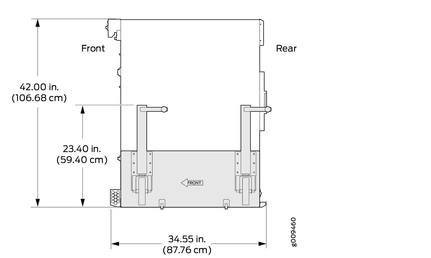
Router Transport Kit Turning Radius
The MX2008 requires a minimum 42 in. (106.7 cm) diameter of space to turn the chassis on the router transport kit (see Figure 1).
The router transport kit does not come with the router. You need to purchase the router transport kit from Juniper Networks. Using the router mounting kit for installing the MX2008 is optional.
The router transport kit handles can be removed to accommodate aisle width.
The weight of the router transport kit is 138.5 lb (63 kg). The maximum recommended height the MX2008 should be lifted from the floor by using the router transport kit is 1.5 in. (3.8 cm).
Router Transport Kit Requirements
Viewed from the side, the MX2008 router with the router transport kit installed measures 42 in. (106.68 cm) high, 36.20 in. (91.95 cm) wide, with the transport kit measuring 23.40 in. (59.4 cm) high (see Figure 2).
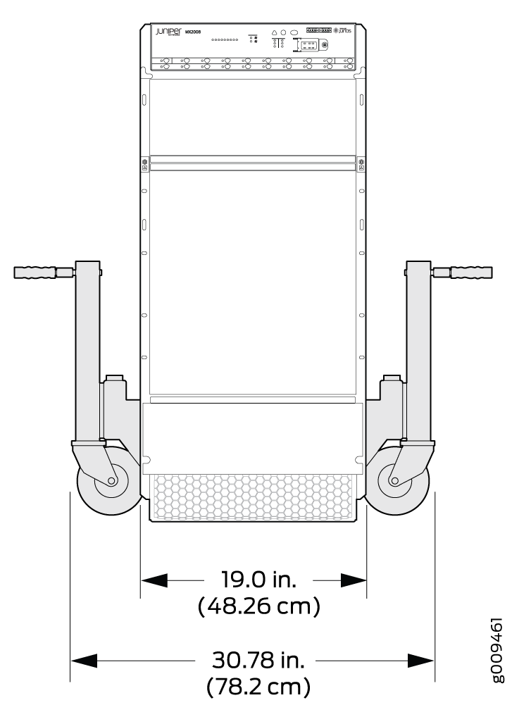
Viewed from the front, the MX2008 router with the router transport kit installed measures 30.78 in. (78.2 cm) wide, with the router measuring 19 in. (48.3 cm) wide (see Figure 3).
See Also
MX2008 Cabinet Airflow Requirements
Before you install the router in a cabinet, you must ensure that ventilation through the cabinet is sufficient to prevent overheating. Consider the following requirements to when planning for chassis cooling:
Ensure that the cool air supply you provide through the cabinet can adequately dissipate the thermal output of the router.
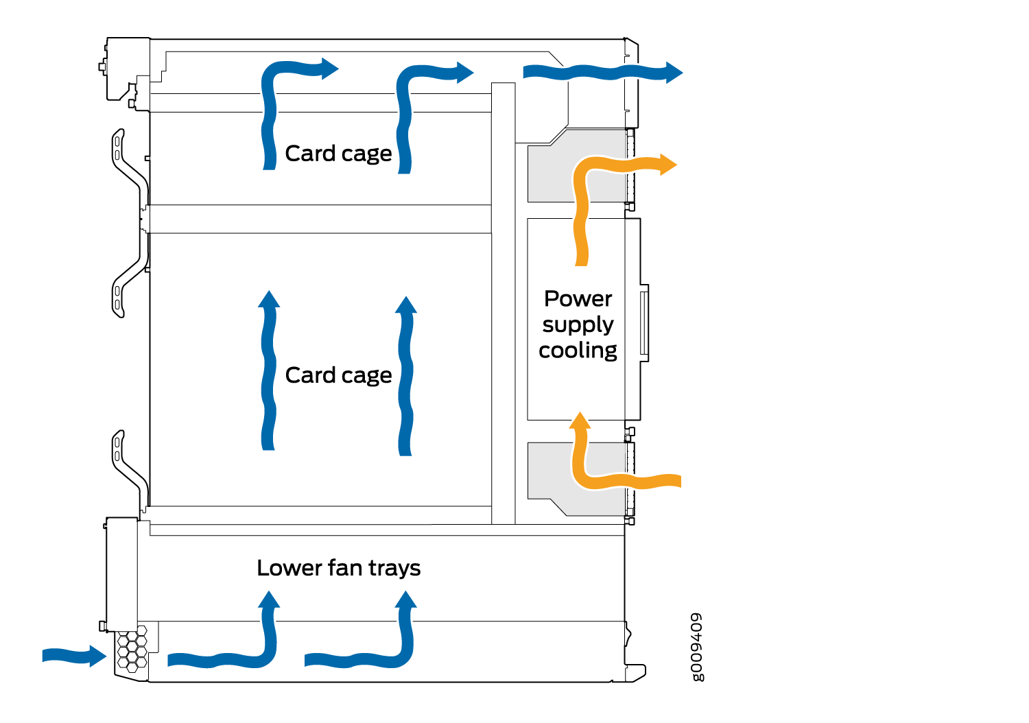
Ensure that the cabinet allows the chassis hot exhaust air to exit from the cabinet without recirculating into the router. An open cabinet (without a top or doors) that employs hot air exhaust extraction from the top allows the best airflow through the chassis. If the cabinet contains a top or doors, perforations in these elements assist with removing the hot air exhaust. For an illustration of chassis airflow, see Figure 4.
Install the router as close as possible to the front of the cabinet so that the cable manager just clears the inside of the front door. This maximizes the clearance in the rear of the cabinet for critical airflow.
Route and dress all cables to minimize the blockage of airflow to and from the chassis.
See Also
MX2008 Cabinet Size and Clearance Requirements
The minimum size cabinet that can accommodate the router is 23.62 in. (60 cm) wide, and 39.37 in. (100 cm) deep. A cabinet larger than the minimum requirement provides better airflow and reduces the chance of overheating. To accommodate a single router, the cabinet must be at least 24 U high that has a clearance of 36.20 in. (91.95 cm) to accommodate the cable managers installed or 40.15 in. (102 cm) to accommodate the extended cable managers.
The minimum front and rear clearance requirements depends on the mounting configuration you choose. The minimum total clearance inside the cabinet is 36.20 in. (91.95 cm) between the inside of the front door and the inside of the rear door.
If you are installing the MX2008 router into a network cabinet, make sure that no hardware, device, rack, or cabinet component obstructs the 34-U rack space from access during installation.
See Also
MX2008 Chassis Moving Guidelines
The fully configured chassis with the cable managers weighs up to 742.2 lb (336.66 kg) for the AC chassis, 664.8 lb (301.55 kg) for the DC chassis, and 261 lb (118.39 kg) with components removed. Observe the following guidelines for moving the router:
Before moving the router, read the Preparing the Site for the MX2008 Router Overview to verify that the intended site meets the specified power, environmental, and clearance requirements.
Do not attempt to move a fully-configured router by yourself. Use a pallet jack with the attachment and a four-person team to maneuver the router into a rack.
Before moving the router, disconnect all external cables.
To move routing devices and components, use the following guidelines:
1 person to lift or move up to 39.7 lb (18.0 kg)
2 people to lift or move up to 70.5 lb (32.0 kg)
3 people to lift or move up to 220 lb (99.8 kg)
4 people to lift or move over 300 lb (136.0 kg)
As when moving any heavy object, lift most of the weight with your legs rather than your back. Keep your knees bent and your back relatively straight and avoid twisting your body as you lift. Balance the load evenly and be sure that your footing is solid.
See Also
MX2008 Physical Specifications
Table 1 and Table 2 summarize the physical specifications for the router chassis and the components.
Item |
Shipping Weight |
|---|---|
Shipping crate and pallet |
358 lb (162.4 kg) |
Unpopulated MX2008 |
261 lb (118.39 kg) |
Unpopulated MX2008 with shipping crate and pallet |
619 lb (280.79 kg) |
Fully populated MX2008 |
|
Fully populated MX2008 with shipping crate and pallet |
1319.88 lb (598.69 kg) |
Description |
Weight |
Width |
Depth |
Height |
|---|---|---|---|---|
Chassis dimensions |
Chassis with components removed: 261 lb (118.39 kg) |
19 in. (48.26 cm) (including the mounting flanges or center-mounting brackets) |
|
42 lb (106.68 cm) |
Chassis with maximum configuration: – AC chassis: 742.2 lb (336.66 kg) – DC chassis: 664.8 lb (301.55 kg) – Chassis with midplane and air filters only: 235.5 lb (106.82 kg) |
19 in. (48.26 cm) (including the mounting flanges or center-mounting brackets) |
|
42 lb (106.68 cm) |
|
Craft interface (with brackets) |
1.5 lb (0.68 kg) |
19.5 in. (49.53 cm) |
4.75 in. (12.065 cm) |
4.0 in. (10.16 cm) |
ADC |
15 lb (6.80 kg) Fully populated with 10 total: 150 lb (68.0 kg) |
1.7 in. (4.31 cm) |
|
17.71 in. (44.98 cm) |
MPC |
MPC without MICs: 23.8 lb (10.79 kg) MPC with MICs: 25 lb (11.34 kg) Fully populated with 10 total: 250 lb (113.39 kg) |
1.25 in. (3.17 cm) |
21.25 in (53.97 cm) |
15.5 in (39.37 cm) |
Blank MPC panel |
5.4 lb (2.45 kg) |
1.25 in. (3.17 cm) |
22.8 in (57.91 cm) |
15.5 in (39.37 cm) |
MIC |
1.2 lb (0.54 kg) |
1.25 in. (3.17 cm) |
6.25 in (15.9 cm) |
6.8 in (17.3 cm) |
AC PSM |
7.0 lb (3.17 kg) Fully populated with 9 total: 63 lb (28.57 kg) |
1.65 in. (4.19 cm) |
7.224 in. (18.34 cm) |
15.10 in. (38.35 cm) |
AC PDM |
12 lb (5.44 kg) Fully populated with 2 total: 24 lb (10.88 kg) |
17.1 in. (43.43 cm) |
4.76 in. (12.09 cm) |
7.361 in. (18.69 cm) |
DC PSM (-48 V) |
7.0 lb (3.17 kg) Fully populated with 9 total: 63 lb (28.57 kg) |
1.65 in. (4.19 cm) |
7.224 in. (18.34 cm) |
15.10 in. (38.35 cm) |
DC PSM (240 V China) |
8.2 lb (3.71 kg) Fully populated with 9 total: 73.8 lb (33.39 kg) |
1.65 in. (4.19 cm) |
7.224 in. (18.34 cm) |
15.10 in. (38.35 cm) |
Universal (HVAC/HVDC) PSM |
8 lb (3.63 kg) Fully populated with 9 total: 72 lb (32.67 kg) |
1.65 in. (4.19 cm) |
7.224 in. (18.34 cm) |
15.10 in. (38.35 cm) |
DC PDM (-48 V) |
8.0 lb (3.62 kg) Fully populated with 2 total: 16 lb (7.25 kg) |
16.8 in. (42.67 cm) |
5.2 in. (13.20 cm) |
4.2 in. (10.66 cm) |
DC PDM (240 V China) |
9.2 lb (4.17 kg) Fully populated with 2 total: 18.40 lb (8.34 kg) |
16.7 in. (42.4 cm) |
5.2 in. (13.20 cm) |
5.12 in. (13.00 cm) |
Universal (HVAC/HVDC) PDM |
8.8 lb (3.98 kg) Fully populated with 2 total: 17.6 lb (7.96 kg) |
16.7 in. (42.4 cm) |
5.2 in. (13.20 cm) |
5.12 in. (13.00 cm) |
Air filter (lower) |
1 lb (0.45 kg) |
16.7 in. (42.4 cm) |
19.7 in. (50 cm) |
0.43 in. (1.1 cm) |
PSM air filter |
0.5 lb (0.23 kg) |
16.0 in. (40.64 cm) |
5.75 in. (14.60 cm) |
0.3 in. (0.76 cm) |
MX2008 SFB2 |
6.9 lb ( kg) Fully populated with 8 total: 55.2 lb ( kg) |
1.7 in. (4.31 cm) |
|
16.23 in. (41.21 cm) |
MX2008 Routing Control Board (MX2008 RCB) |
6.9 lb ( kg) Fully populated with 2 total: 13.8 lb ( kg) |
1.7 in. (4.31 cm) |
|
16.225 in. (41.21 cm) |
Fan tray |
25 lb (11.34 kg) Fully populated with 2 total: 50 lb (22.68 kg) |
16.70 in. (42.41 cm) |
28.16 in. (71.52 cm) |
2.62 in. (6.65 cm) |
Standard cable manager (bottom) |
7.0 lb (3.17 kg) |
18.99 in. (48.23 cm) |
2.80 in. (7.11 cm) |
7.428 in. (18.86 cm) |
Standard DC cable manager (rear) |
1.2 lb (0.54 kg) Fully populated with 2 total: 2.4 lb (1.08 kg) |
16.85 in. (42.79 cm) |
2.93 in. (7.44 cm) |
2.73 in. (6.93 cm) |
Extended cable manager (bottom) |
10.2 lb (4.62 kg) |
18.98 in. (48.20 cm) |
3.95 in. (10.03 cm) |
7.55 in. (19.17 cm) |
Extended DC cable manager (rear) |
0.7 lb (0.32 kg) Fully populated with 2 total: 1.4 lb (1.8 kg) |
16.78 in. (42.62 cm) |
2.93 in. (7.44 cm) |
2.72 in. (6.90 cm) |
Standard EMI cover |
7.2 lb (3.3 kg) |
17.45 in. (44.32 cm) |
3.50 in. (8.9 cm) |
18.86 in. (47.9 cm) |
Extended EMI cover |
9.65 lb (4.4 kg) |
17.45 in. (44.32 cm) |
5.40 in. (13.7 cm) |
18.86 in. (47.9 cm) |
See Also
MX2008 Rack Requirements
- Rack Size and Strength
- Spacing of Mounting Bracket and Flange Holes
- Connection to the Building Structure
Rack Size and Strength
The MX2008 router is designed for installation in a rack that complies with either of the following standards:
-
A 19-in. rack as defined in Cabinets, Racks, Panels, and Associated Equipment (document number EIA-310-D) published by the Electronics Components Industry Association (http://www.ecianow.org/).
-
A 600-mm rack as defined in the four-part Equipment Engineering (EE); European telecommunications standard for equipment practice (document numbers ETS 300 119-1 through 119-4) published by the European Telecommunications Standards Institute (http://www.etsi.org). The horizontal spacing between the rails in a rack that complies with this standard is usually wider than the mounting brackets, which measure 19.2 in. (48.8 cm) from the outer edge to outer edge. Use approved wing devices to narrow the opening between the rails as required.
-
A 23-in. rack using appropriate 23-in. to 19-in. rack adapters and an appropriate installation shelf that supports the chassis at the correct vertical position to properly line up the rack mount holes. Juniper Networks does not supply this hardware, but consideration for the size and weight of the chassis is important for a safe installation.
The rack rails must be spaced widely enough to accommodate the chassis’s external dimensions: 59.50 in. (151.1 cm) high, 36.20 in. (91.95 cm) deep, and 19 in. (48.3 cm) wide. The outer edges of the front-mounting flanges extend the width to 19.2 in. (48.8 cm), The spacing of rails and adjacent racks must also allow for the clearances around the chassis and rack that are specified in Clearance Requirements for Airflow and Hardware Maintenance for the MX2008 Router. The cable manager and EMI cover on the front of the chassis is 36.20 in. (91.95 cm) deep. An extended cable manager extends the depth to 40.15 in. (102 cm).
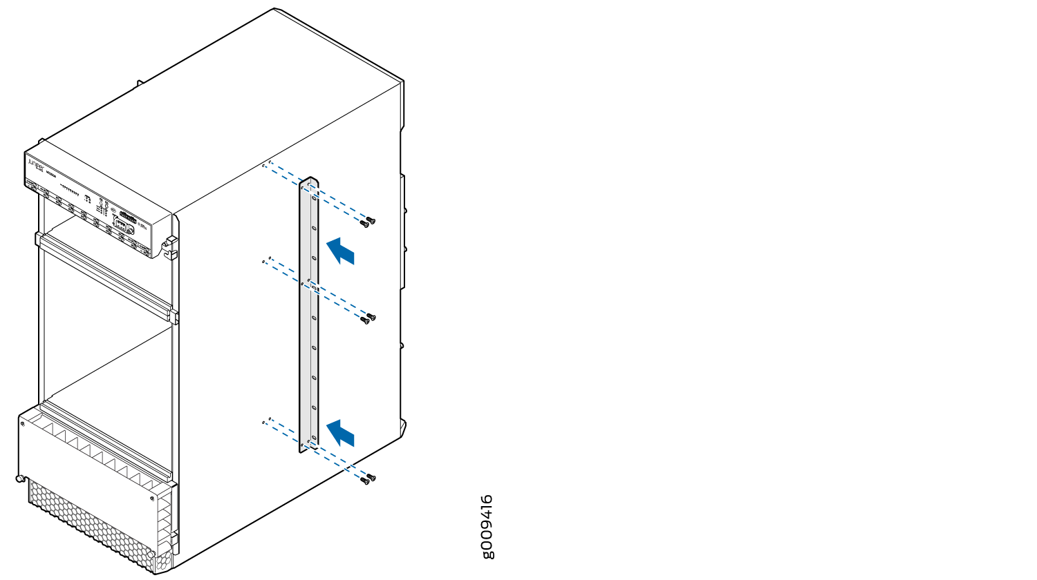
In an open-frame rack, center-mounting is required because the more even distribution of weight provides greater stability. For center-mounting, you use the mounting brackets attached to the center of the chassis for rack mounting (see Figure 6).
For instructions about installing the mounting hardware, see Installing the MX2008 Mounting Hardware for a Four-Post Rack or Cabinet.
The weight and depth of the router depends on the type of cable manager installed.
With the standard or extended cable manager installed, use these guidelines:
-
The rack must have sufficient vertical usable space to accommodate the height of the router: 59.50 in. (151.1 cm). You can install one chassis in a rack. A typical four-post rack measures 84 in. (213.4 cm) high, 24 in. (61 cm) through 30 in. (76.2 cm) deep, and 19 in. (48.3 cm) wide (see Figure 5). A typical open-frame rack measures 84 in. (213.4 cm) high and 19 in. (48.3 cm) wide.
Note:A U is the standard rack unit defined in Cabinets, Racks, Panels, and Associated Equipment (document number EIA-310-D) published by the Electronics Industry Association (http://www.eia.org).
-
The location of the rack must provide sufficient space to accommodate the depth of the router. The chassis with the standard cable manager is 36.20 in. (91.95 cm) deep.
-
The chassis with the extended cable manager is 40.15 in. (102 cm) deep.
The rack must be strong enough to support the weight of the fully configured router, up to 742.2 lb (336.66 kg).
For a complete list of chassis configuration and individual line card and component weights and measurements, see MX2008 Physical Specifications.
There must be a minimum of 24-U of usable rack space when installing the MX2008 router.
Spacing of Mounting Bracket and Flange Holes
The holes in the mounting brackets and front-mount-flanges used to attach the chassis to a rack are spaced at 1 U (1.75 in.). The router can be mounted in any rack that provides holes spaced at those distances. Figure 6 shows the chassis center-mounting brackets.
Connection to the Building Structure
Always secure the rack to the structure of the building. If your geographical area is subject to earthquakes, bolt the rack to the floor. For maximum stability, also secure the rack to ceiling brackets.
See Also
MX2008 Router Environmental Specifications
Table 3 specifies the environmental specifications required for normal router operation. In addition, the site should be as dust-free as possible.
Description |
Value |
|---|---|
Relative humidity |
Normal operation ensured in relative humidity range of 5% through 90%, noncondensing |
Temperature |
Normal operation ensured in temperature range of 32°F (0°C) through 104°F (40°C) Nonoperating storage temperature in shipping container: –40°F (–40°C) through 158°F (70°C) |
Seismic |
Designed to meet Telcordia Technologies Zone 4 earthquake requirements |
Maximum thermal output |
AC input power: 129,280 BTU/hour DC input power: 129,280 BTU/hour |
Install the router only in restricted areas, such as dedicated equipment rooms and equipment closets, in accordance with Articles 110-16, 110-17, and 110-18 of the National Electrical Code, ANSI/NFPA 70.
See Also
MX2008 Router Grounding Specifications
- MX2008 Chassis Grounding Points Specifications
- MX2008 Router Grounding Cable Lug Specifications
- MX2008 Router Grounding Cable Specifications
MX2008 Chassis Grounding Points Specifications
To meet safety and electromagnetic interference (EMI) requirements and to ensure proper operation, the router must be adequately grounded before power is connected. To ground AC-powered or DC-powered routers, you must connect a grounding cable to earth ground and then attach it to the chassis grounding points by using the two screws provided (see Figure 7).
You must install the MX2008 router in a restricted-access location and ensure that the chassis is always properly grounded. The MX2008 router has a two-hole protective grounding terminal provided on the chassis. See Figure 7. Under all circumstances, use this grounding connection to ground the chassis. For AC-powered systems, you must also use the grounding wire in the AC power cord along with the two-hole grounding lug connection. This tested system meets or exceeds all applicable EMC regulatory requirements with the two-hole protective grounding terminal.
MX2008 Router Grounding Cable Lug Specifications
Before you install the router, a licensed electrician must attach a cable lug to the grounding and power cables that you supply. A cable with an incorrectly attached lug can damage the router.
To ground AC–powered or DC–powered routers, connect a grounding cable to earth ground and then attach it to the chassis grounding points by using two washers and nuts. The top pair of grounding points fits UNC 1/4–20 nuts (American), and the lower pair fits M6 nuts (European). The grounding points are spaced at 0.625-in. (15.86-mm) centers. The cable lugs get attached to the grounding cable, and the two UNC 1/4–20 nuts and washers are used to secure the grounding cable to the top pair of grounding points.
The router is installed in a restricted access location. It has a separate protective earthing terminal (Metric [–M6] and English [–¼-20] screw ground lugs) provided on the chassis in addition to the grounding pin of the power supply cord. This separate protective earth terminal must be permanently connected to earth.
The MX2008 supports 4-AWG DC power cable lugs for 80-A input and 60-A input (see Figure 8).
Table 4 summarizes the specifications for the power cables, which you must supply.
|
Cable Type |
Quantity and Specification |
|---|---|
|
Power |
Eighteen pairs of 4-AWG (21.2 mm2), used with 60-A or 80-A PDM. Minimum 90°C wire, or as required by the local code. You can select 60-A or 80-A input feed capacity on the DC PDM by setting the DIP switch on the PDM to the rated amperage of the DC power input feeds. |
MX2008 Router Grounding Cable Specifications
The grounding cable must be minimum 4 AWG, or as required by the local code.
Additional grounding is provided to an AC-powered router when you plug its PDMs into grounded AC power receptacles.
To comply with intrabuilding lightning and surge requirements, intrabuilding wiring must be shielded, and the shield for the wiring must be grounded at both ends.
The router is installed in a restricted-access location. It has a separate protective earthing terminal (Metric [–M6] and English [–¼-20] screw ground lugs) provided on the chassis in addition to the grounding pin of the power supply cord. This separate protective earth terminal must be permanently connected to earth.
See Also
MX2008 Site Preparation Checklist
The checklist in Table 5 summarizes the tasks you must perform when preparing a site for router installation.
Item or Task |
For More Information |
Performed By |
Date |
|---|---|---|---|
Environment |
|||
Verify that environmental factors such as temperature and humidity do not exceed router tolerances. |
|||
Power |
|||
Measure distance between external power sources and router installation site. |
MX2008 DC Power Distribution Module (-48 V) Description MX2000 DC Power Distribution Module (240 V China) Description MX2008 High-Voltage Universal (HVAC/HVDC) Power Distribution Module Description |
||
Locate sites for connection of system grounding. |
|||
Calculate the power consumption and requirements. |
MX2008 High-Voltage Second-Generation Universal Power Requirements |
||
Rack |
|||
Verify that your rack meets the minimum requirements for the installation of the router. |
|||
Plan rack or cabinet location, including required space clearances. Note:
If you are installing the MX2008 router into a network cabinet, make sure that no hardware, device, rack, or cabinet component obstructs the 24-U rack space from access during installation. |
MX2008 Cabinet Size and Clearance Requirements Clearance Requirements for Airflow and Hardware Maintenance for the MX2008 Router |
||
If a rack is used, secure rack to floor and building structure. |
|||
Cables and Transceivers |
|||
Acquire cables and transceivers:
|
Fiber-Optic Cable Signal Loss, Attenuation, and Dispersion Calculating Power Budget and Power Margin for Fiber-Optic Cables |
||
Plan the cable routing and management. |
|||
See Also
Clearance Requirements for Airflow and Hardware Maintenance for the MX2008 Router
When planning the installation site, you need to allow sufficient clearance around the rack (see Figure 9 and Figure 10):
-
For the cooling system to function properly, the airflow around the chassis must be unrestricted.
-
For service personnel to remove and install hardware components, there must be adequate space at the front and back of the router. At least 36 in. (91.44 cm) is required both in front of and behind the router.
Airflow must always be from front to back with respect to the rack to ensure that fresh air from the front of the rack is supplied to the inlets, and exhaust exits the rear of the rack. Care must also be taken around cables to ensure that no leakage of air in situations where recirculation may result.
Note:There are no additional clearance requirements to accommodate the depth of the MX2008 power distribution modules (PDMs) and power supply modules (PSMs); they are within specification.
-
An MX2008 router with an extended cable manager requires extra clearance to accommodate the depth of 40.15 in. (102 cm).
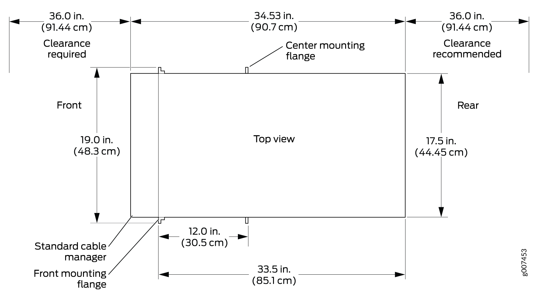
There must be a minimum of 24-U of usable rack space when you install the MX2008 router.