Maintaining MX2008 Components
Tools and Parts Required for Replacing MX2008 Hardware Components
To replace hardware components, you need the tools and parts listed in Table 1.
Components |
Tool or Part |
|---|---|
All |
Electrostatic discharge (ESD) grounding wrist strap |
AC power supply module |
Phillips (+) screwdrivers, number 1 and 2 |
AC power distribution module Three-phase delta AC PDM Three-phase wye AC PDM |
Phillips (+) screwdriver, number 2 to access the metal AC wiring compartment 7/16-in. (11 mm) hexagonal-head external drive socket wrench, or nut driver, with a torque range between 23 lb-in. (2.6 Nm) and 25 lb-in. (2.8 Nm) to attach the ground wire. 1/4-in. slotted screwdriver and 5/32-in. (4 mm) Allen wrench to attach input terminal wires of the AC power cord. |
AC power cord |
Phillips (+) screwdrivers, numbers 1 and 2 7/16-in. (11 mm) hexagonal-head external drive socket wrench, or nut driver, with a torque range between 23 lb-in. (2.6 Nm) and 25 lb-in. (2.8 Nm) to attach the ground wire. 1/4-in. slotted screwdriver and 5/32-in. (4 mm) Allen wrench to attach input terminal wires of the AC power cord. |
Craft interface |
Phillips (+) screwdrivers, numbers 1 and 2 |
DC power distribution module |
Phillips (+) screwdrivers, numbers 1 and 2 7/16-in. (11 mm) hexagonal-head external drive socket wrench, or nut driver, with a torque range between 23 lb-in. (2.6 Nm) and 25 lb-in. (2.8 Nm) to attach the ground wire. 1/4-in. slotted screwdriver and 5/32-in. (4 mm) Allen wrench to attach input terminal wires of the AC power cord. |
DC power supply cable |
7/16-in. (11 mm) nut driver or socket wrench CAUTION: You must use an appropriate torque-controlled tool to tighten the nuts. Apply excessive torque damages the terminal studs and the PDM. The absolute maximum that may be applied to this nut is between 23 lb-in. (2.6 Nm) and 25 lb-in. (2.8 Nm). |
Fan trays (upper and lower) |
Phillips (+) screwdrivers, numbers 1 and 2 |
Air Baffle |
Phillips (+) screwdrivers, numbers 1 and 2 |
MPC |
Phillips (+) screwdrivers, numbers 1 and 2 Blank panels (if component is not reinstalled) Electrostatic bag or antistatic mat |
MIC |
Phillips (+) screwdrivers, numbers 1 and 2 Rubber safety cap for fiber-optic MICs Flat-blade (–) screwdriver Electrostatic bag or antistatic mat Blank panels (if component is not reinstalled) |
Routing Engine and Control Board (RCB) |
Phillips (+) screwdrivers, numbers 1 and 2 Electrostatic discharge (ESD) grounding wrist strap Blank panels (if component is not reinstalled) |
SFB |
Phillips (+) screwdrivers, numbers 1 and 2 Electrostatic discharge (ESD) grounding wrist strap Blank panels (if component is not reinstalled) |
Serial cable to Auxiliary or Console Routing Engine port |
Flat-blade (–) screwdriver |
PSM air filter |
Phillips (+) screwdrivers, numbers 1 and 2 |
Card-cage air filter |
Phillips (+) screwdrivers, numbers 1 and 2 |
Air filter (lower) |
Phillips (+) screwdrivers, numbers 1 and 2 |
See Also
Tools and Parts Required to Remove Components from an MX2008 Router
To remove components from the router or the router from a rack, you need the following tools and parts:
2.5-mm flat-blade (–) screwdriver, for detaching alarm relay terminal block
7/16-in. (11 mm) nut driver
Blank panels to cover empty slots
EMI (electromagnetic interference) covers—shipped with router
Electrostatic bag or antistatic mat, for each component
Electrostatic discharge (ESD) grounding wrist strap
Flat-blade (–) screwdriver
Pallet jack with attachment—recommended
Phillips (+) screwdrivers, numbers 1 and 2
Rubber safety cap for fiber-optic interfaces or cable
Wire cutters
See Also
Tools and Parts Required to Maintain the MX2008 Hardware Components
To maintain hardware components, you need the following tools and parts:
ESD grounding wrist strap
Flat-blade (–) screwdriver
Phillips (+) screwdriver, number 1 and number 2
See Also
Replacing the MX2008 Extended Cable Manager
- Removing the MX2008 Extended Cable Manager
- Removing the MX2008 Extended DC Cable Manager
- Installing the MX2008 Extended Cable Manager
- Installing the MX2008 Extended DC Cable Manager
Removing the MX2008 Extended Cable Manager
To remove the extended cable manager:
- Attach an electrostatic discharge (ESD) grounding strap to your bare wrist, and connect the strap to one of the ESD points on the chassis.
- To remove the cover, loosen the two captive screws on the extended cable manager cover. Set the extended cable manager cover aside.
- Remove the eight screws that secure the extended cable manager to the chassis as shown in Figure 1.
- Pull the extended cable manager away from the chassis.

Removing the MX2008 Extended DC Cable Manager
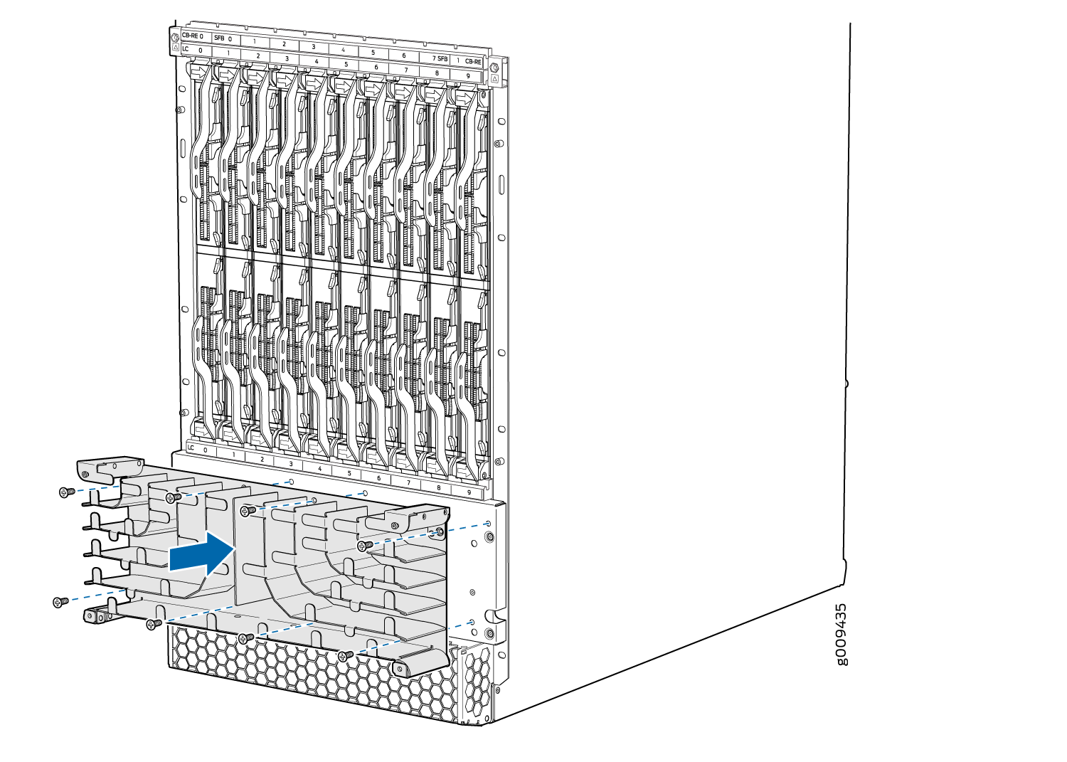
To remove the extended DC cable manager (see Figure 2):
- Attach an electrostatic discharge (ESD) grounding strap to your bare wrist, and connect the strap to one of the ESD points on the chassis.
- Using a Phillips (+) screwdriver (number 1 or 2), loosen the two captive screws on the DC cable manager.
- Grasp the extended DC cable manager, lift up and pull straight out from the DC PDM on the rear of the chassis.
- Place the extended DC cable manager into an electrostatic bag and set it aside.
To remove the cable manager for the DC PDM (240 V China) and the universal (HVAC/HVDC) PDM (see Figure 3):
-
Attach an electrostatic discharge (ESD) grounding strap to your bare wrist, and connect the strap to an approved site ESD grounding point. See the instructions for your site.
-
Using a screwdriver, loosen the two screws on each side of the cable manager (see Figure 3).
Figure 3: Removing the DC Cable Manager for DC PDM (240 V China) and the Universal (HVAC/HVDC) PDM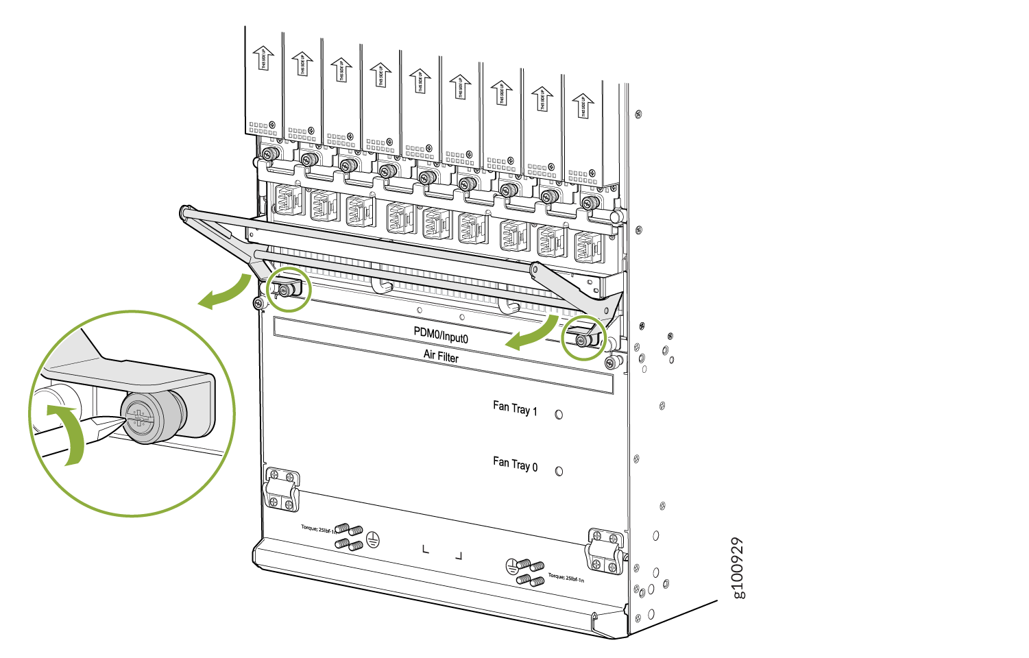
-
Grasp the DC cable manager, lift up and pull straight out from the DC PDM on the rear of the chassis.
-
Place the DC cable manager into an electrostatic bag and set it aside.
Installing the MX2008 Extended Cable Manager
To install the extended cable manager (see Figure 4):
- Attach an electrostatic discharge (ESD) grounding strap to your bare wrist, and connect the strap to one of the ESD points on the chassis.
- Position the extended cable manager on the studs below the lower card cage.
- Attach the extended cable manager using eight screws as shown in Figure 4.
- Replace the cable manager cover, and secure it with the two captive screws.
Installing the MX2008 Extended DC Cable Manager
To install the extended DC cable manager (see Figure 5):
- Attach an electrostatic discharge (ESD) grounding strap to your bare wrist, and connect the strap to one of the ESD points on the chassis.
- Position the extended DC cable manager over the two slots located on both sides of the DC PDM.
- Lift the extended DC cable manager slightly up while inserting the two flanges into the slots on both sides of the DC PDM.
- Push the extended DC cable manager into place.
- Tighten the two captive screws to secure the extended DC cable manager.

To install the DC cable manager for the DC PDM (240 V China) or the universal (HVAC/HVDC) PDM (see Figure 6):
-
Attach an electrostatic discharge (ESD) grounding strap to your bare wrist, and connect the strap to one of the ESD points on the chassis.
-
Position the DC cable manager over the two slots located on both sides of the DC PDM.
-
Lift the DC cable manager slightly up while inserting the two flanges into the slots on both sides of the DC PDM.
Figure 6: Installing the DC Cable Manager on the DC PDM (240 V China) and Universal (HVAC/HVDC) PDM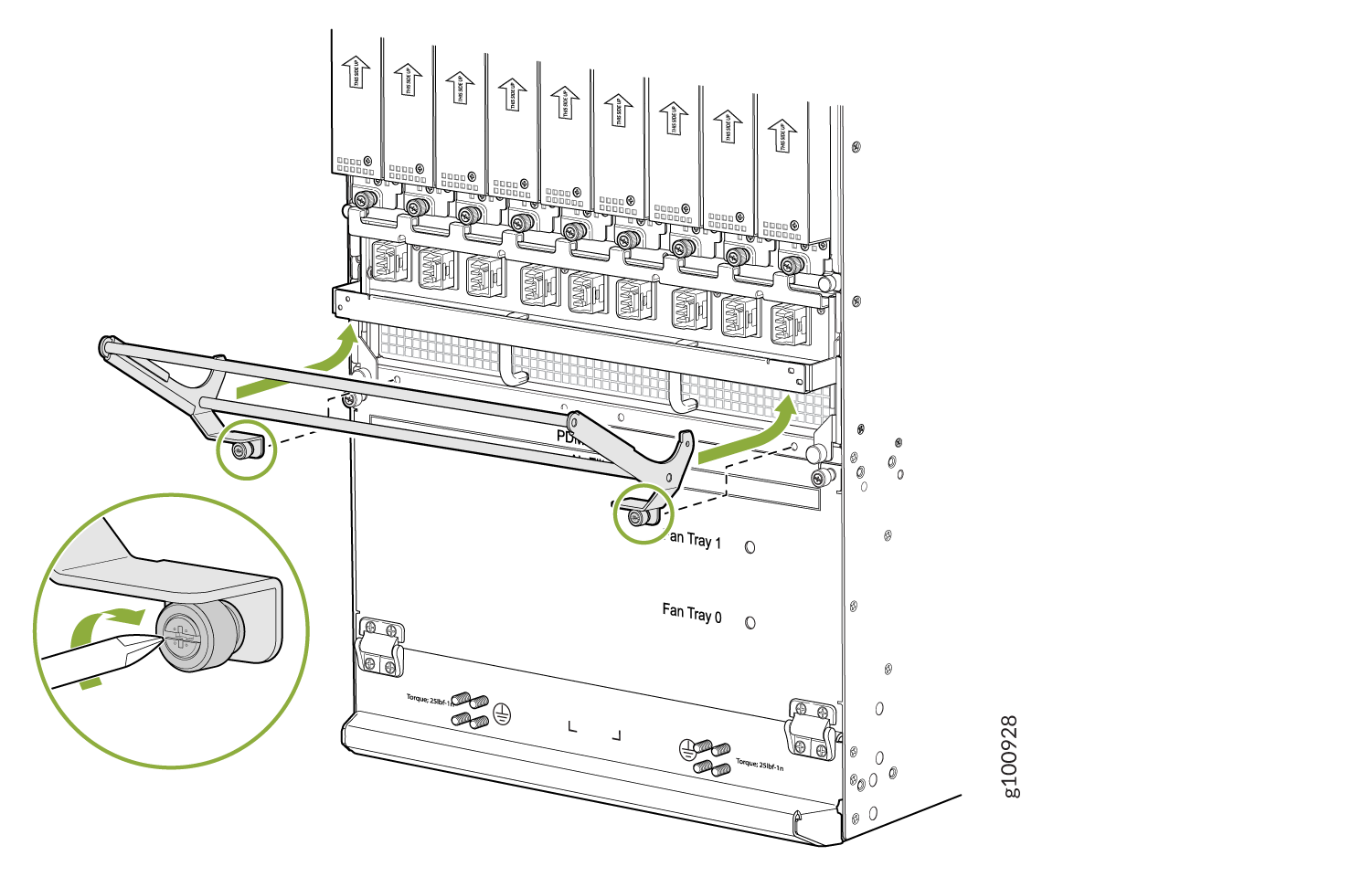
-
Push down to secure the DC cable manager in place. Tighten the screws using a screwdriver. See Figure 6.
Replacing the MX2008 Craft Interface
- Disconnecting the Alarm Relay Wires from the MX2008 Craft Interface
- Removing the MX2008 Craft Interface
- Installing the MX2008 Craft Interface
- Connecting the Alarm Relay Wires to the MX2008 Craft Interface
Disconnecting the Alarm Relay Wires from the MX2008 Craft Interface
To disconnect the alarm relay wires from the router and an alarm-reporting device (see Figure 7):
- Disconnect the existing wire at the external device.
- Attach an electrostatic discharge (ESD) grounding strap to your bare wrist, and connect the strap to one of the ESD points on the chassis.
- Using a 2.5-mm flat-blade screwdriver, loosen the small screws on the face of the terminal block and remove the block from the relay contact.
- Using the 2.5-mm flat-blade screwdriver, loosen the small screws on the side of the terminal block. Remove existing wires from the slots in the front of the block (see Table 2).
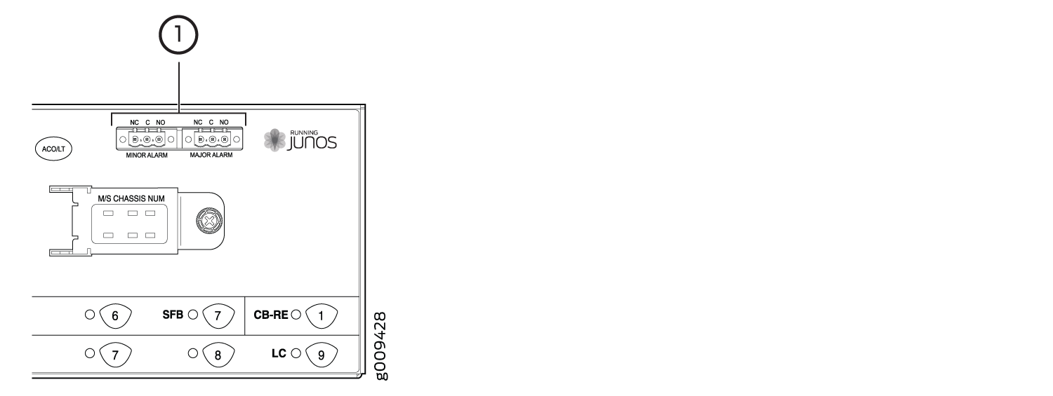
|
Function No. |
Label |
Description |
|---|---|---|
|
1 |
MINOR ALARM—[NC C NO] MAJOR ALARM—[NC C NO] |
The alarm relays consist of three terminal contacts with a normal closed (NC), common (C), and normal open (NO) relays that signal a minor or major alarm when broken. |
Removing the MX2008 Craft Interface
To remove the craft interface (see Figure 8):
- Attach an electrostatic discharge (ESD) grounding strap to your bare wrist, and connect the strap to one of the ESD points on the chassis.
- Detach any external devices connected to the craft interface.
- Loosen the two captive screws at the left and right sides of the craft interface faceplate by using the Torx (T10) screwdriver.
- Grasp the craft interface faceplate and carefully tilt it toward you until it is horizontal.
- Disconnect the ribbon cable from the back of the faceplate by gently pressing on both sides of the latch with your thumb and forefinger. Remove the craft interface from the chassis.
Installing the MX2008 Craft Interface
To install the craft interface (see Figure 9):
- Attach an electrostatic discharge (ESD) grounding strap to your bare wrist, and connect the strap to one of the ESD points on the chassis.
- Grasp the craft interface with one hand, and hold the bottom edge of the craft interface with the other hand to support its weight.
- Orient the ribbon cable so that it plugs into the connector socket. The connector is keyed and can be inserted only one way. The pin on the right side of the craft interface indicates the positioning.
- Align the bottom of the craft interface with the sheet metal above the card cage, and press it into place.
- Tighten the two screws on the left and right sides of the craft interface faceplate by using the Torx (T10) screwdriver.
- Reattach any external devices connected to the craft interface.
Connecting the Alarm Relay Wires to the MX2008 Craft Interface
To connect the alarm relay wires between a router and an alarm-reporting device (see Figure 10):
- Prepare the required length of replacement wire with gauge between 28 AWG (0.08 mm2) and 14 AWG (2.08 mm2).
- Insert the replacement wires into the slots in the front of the block (see Table 3). Use a 2.5-mm flat-blade screwdriver to tighten the screws and secure the wire.
- Attach an electrostatic discharge (ESD) grounding strap to your bare wrist, and connect the strap to one of the ESD points on the chassis.
- Plug the terminal block into the relay contact, and use a 2.5-mm flat-blade screwdriver to tighten the screws on the face of the block.
- Attach the other end of the wires to the external device.
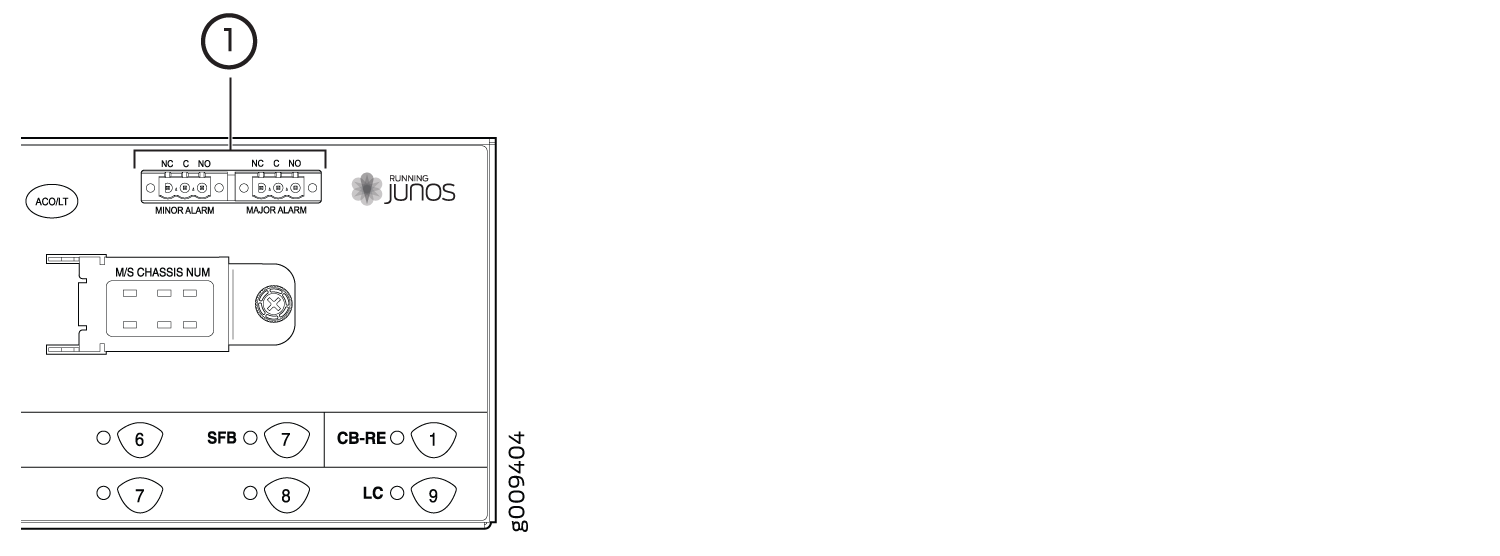
|
Function No. |
Label |
Description |
|---|---|---|
|
1 |
MINOR ALARM—[NC C NO] MAJOR ALARM—[NC C NO] |
The alarm relays consist of three terminal contacts with a normal closed (NC), a common (C), and a normal open (NO) relay that signal a minor or major alarm when broken. |
Replacing the MX2008 Standard EMI Cover
Removing the MX2008 Standard EMI Cover
To remove the electromagnetic interference (EMI) card-cage cover (see Figure 11).
-
Pull the cover away from the router toward you to remove
it.
Figure 11: Removing the EMI Card-Cage Cover
Installing the MX2008 Standard EMI Cover
The MPCs require an EMI cover to reduce the risk of radio frequency interference disturbance that affects an electrical circuit because of electromagnetic interference emitted from an external source. The EMI cover is designed to reduce the electromagnetic interference (EMI) to comply with the Federal Communications Commission (FCC) requirements.
To install the EMI card-cage cover (see Figure 12):
-
Tighten the four captive screws to secure the EMI cover
in place.
Figure 12: Installing the EMI Card-Cage Cover
Replacing the MX2008 Extended EMI Cover
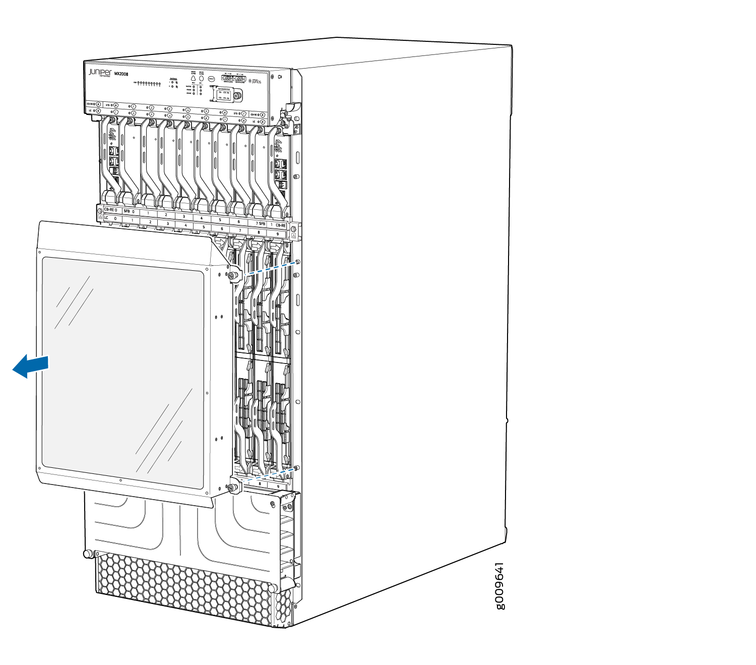
Removing the MX2008 Extended EMI Cover
The extended electromagnetic interference (EMI) cover attaches to the router over the card cage and tilts out from the top.
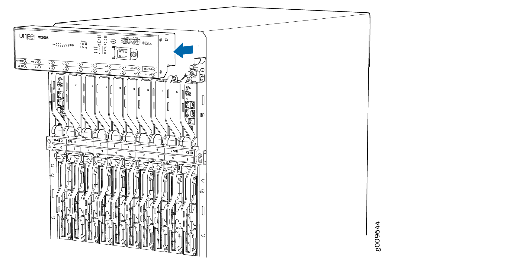
To remove the extended electromagnetic interference (EMI) card-cage cover (see Figure 14):
- Using a number 2 Phillips (+) screwdriver, remove the
two mounting screws from the mounting brackets on either side of the
card cage. Then remove the mounting brackets (see Figure 13).Figure 13: Removing the Extended EMI Cover Mounting Brackets
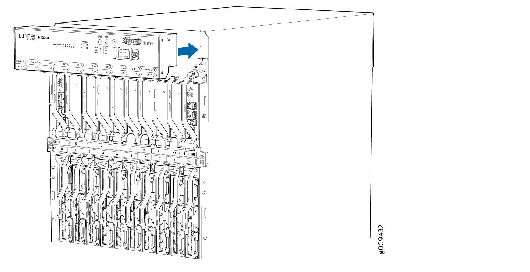
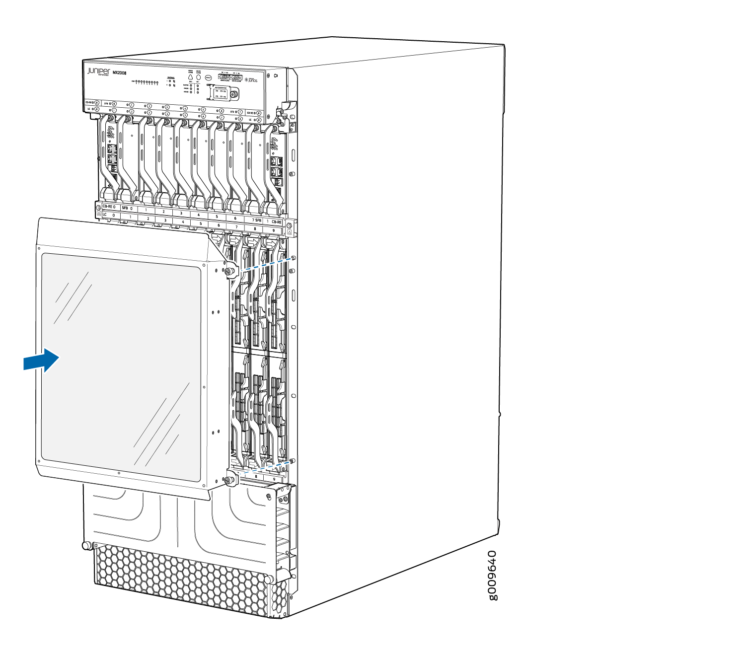
Installing the MX2008 Extended EMI Cover
The extended electromagnetic interference (EMI) covers attaches to the router over the card cage.
- Using a number 2 Phillips (+) screwdriver, secure the
extended EMI cover mounting brackets to the sides of the card cage
by using the four screws provided (two on each side) (see Figure 15).Figure 15: Installing the Extended EMI Cover Mounting Brackets