Connecting the MX2008 to the Network
Tools and Parts Required for MX2008 Router Connections
To connect the router to management devices and MPCs, you need the following tools and parts:
Phillips (+) screwdrivers, numbers 1 and 2
2.5 mm flat-blade (–) screwdriver
2.5 mm Phillips (+) screwdriver
Wire cutters
Electrostatic discharge (ESD) grounding wrist strap
See Also
Connecting the Alarm Relay Wires to the MX2008 Craft Interface
To connect the alarm relay wires between a router and an alarm-reporting device (see Figure 1):
- Prepare the required length of replacement wire with gauge between 28 AWG (0.08 mm2) and 14 AWG (2.08 mm2).
- Insert the replacement wires into the slots in the front of the block (see Table 1). Use a 2.5-mm flat-blade screwdriver to tighten the screws and secure the wire.
- Attach an electrostatic discharge (ESD) grounding strap to your bare wrist, and connect the strap to one of the ESD points on the chassis.
- Plug the terminal block into the relay contact, and use a 2.5-mm flat-blade screwdriver to tighten the screws on the face of the block.
- Attach the other end of the wires to the external device.
Function No. |
Label |
Description |
|---|---|---|
1 |
MINOR ALARM—[NC C NO] MAJOR ALARM—[NC C NO] |
The alarm relays consist of three terminal contacts with a normal closed (NC), a common (C), and a normal open (NO) relay that signal a minor or major alarm when broken. |
See Also
Disconnecting the Alarm Relay Wires from the MX2008 Craft Interface
To disconnect the alarm relay wires from the router and an alarm-reporting device (see Figure 2):
- Disconnect the existing wire at the external device.
- Attach an electrostatic discharge (ESD) grounding strap to your bare wrist, and connect the strap to one of the ESD points on the chassis.
- Using a 2.5-mm flat-blade screwdriver, loosen the small screws on the face of the terminal block and remove the block from the relay contact.
- Using the 2.5-mm flat-blade screwdriver, loosen the small screws on the side of the terminal block. Remove existing wires from the slots in the front of the block (see Table 2).
Function No. |
Label |
Description |
|---|---|---|
1 |
MINOR ALARM—[NC C NO] MAJOR ALARM—[NC C NO] |
The alarm relays consist of three terminal contacts with a normal closed (NC), common (C), and normal open (NO) relays that signal a minor or major alarm when broken. |
See Also
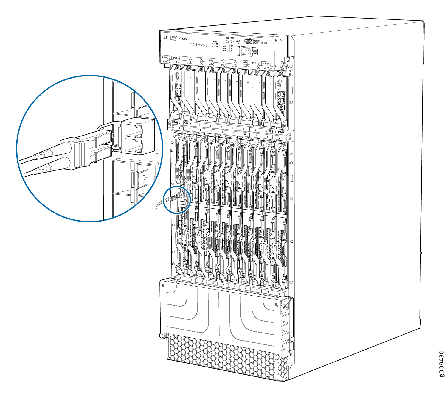
Connecting MPC or MIC Cables to the MX2008 Router
To connect the MPCs or MICs to the network (see Figure 3):